
ErgoDash Custom Mechanical Keyboard
TL;DR
For the sake of brevity, the abridged version of the core components and features.
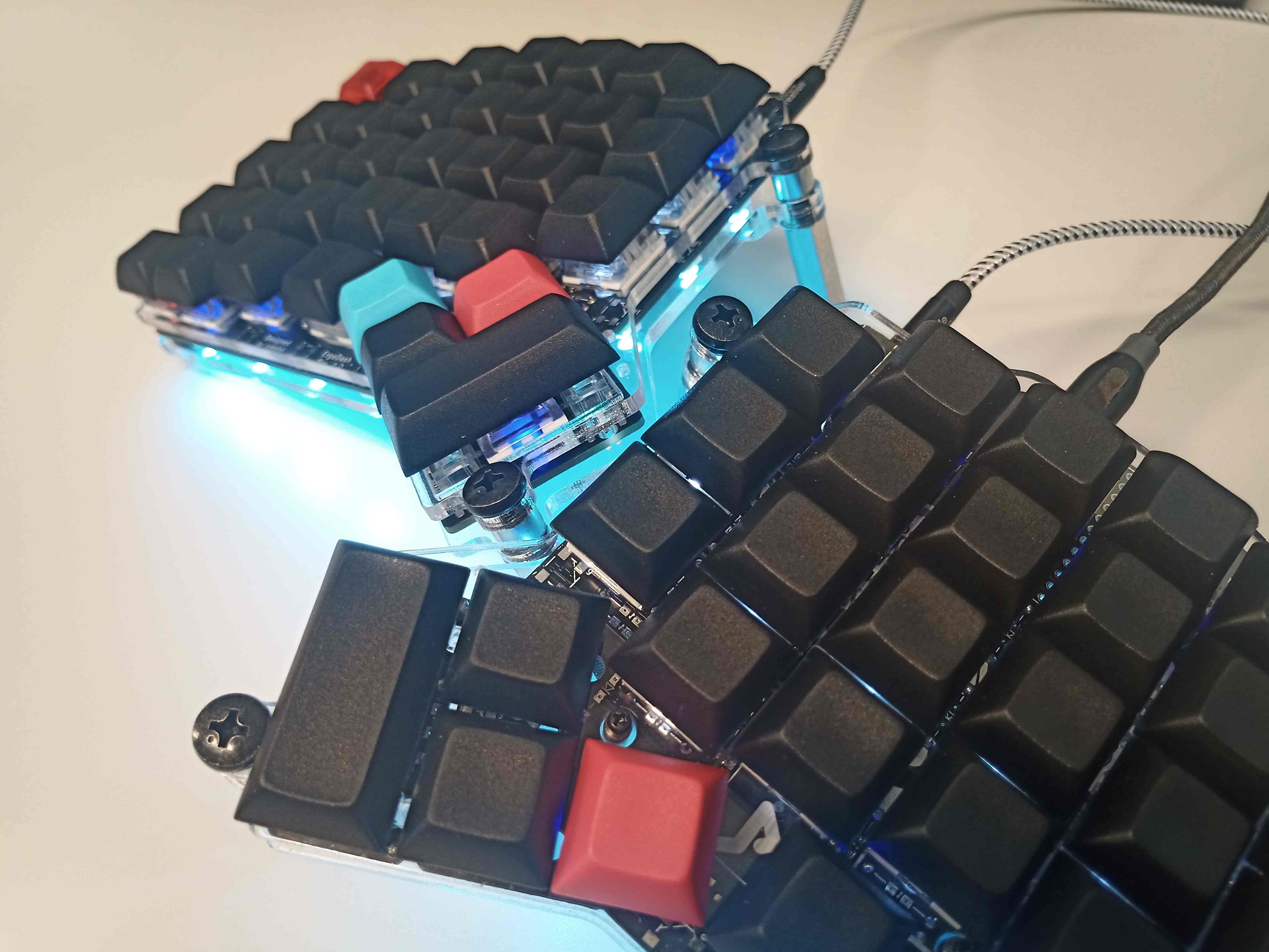
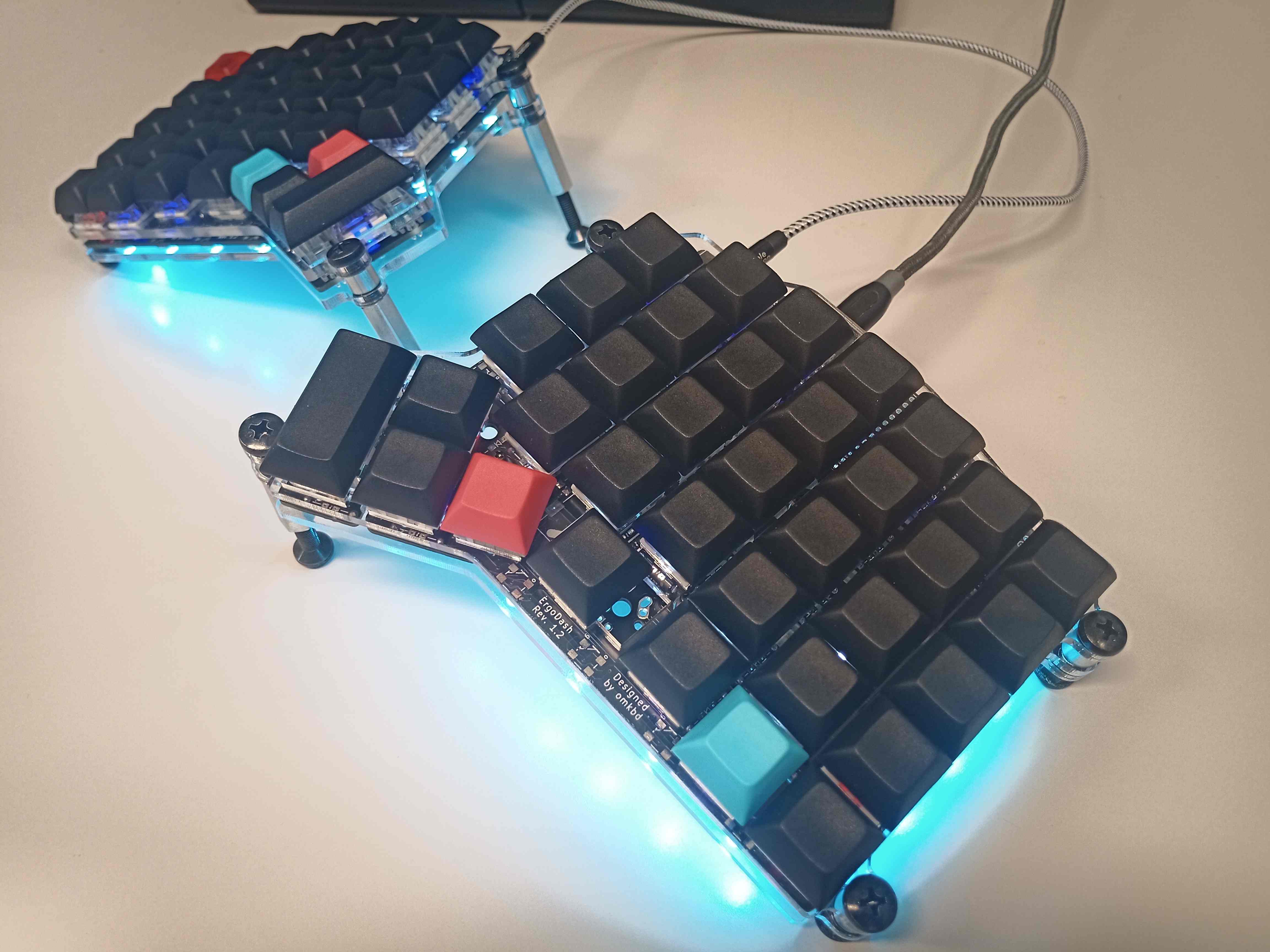
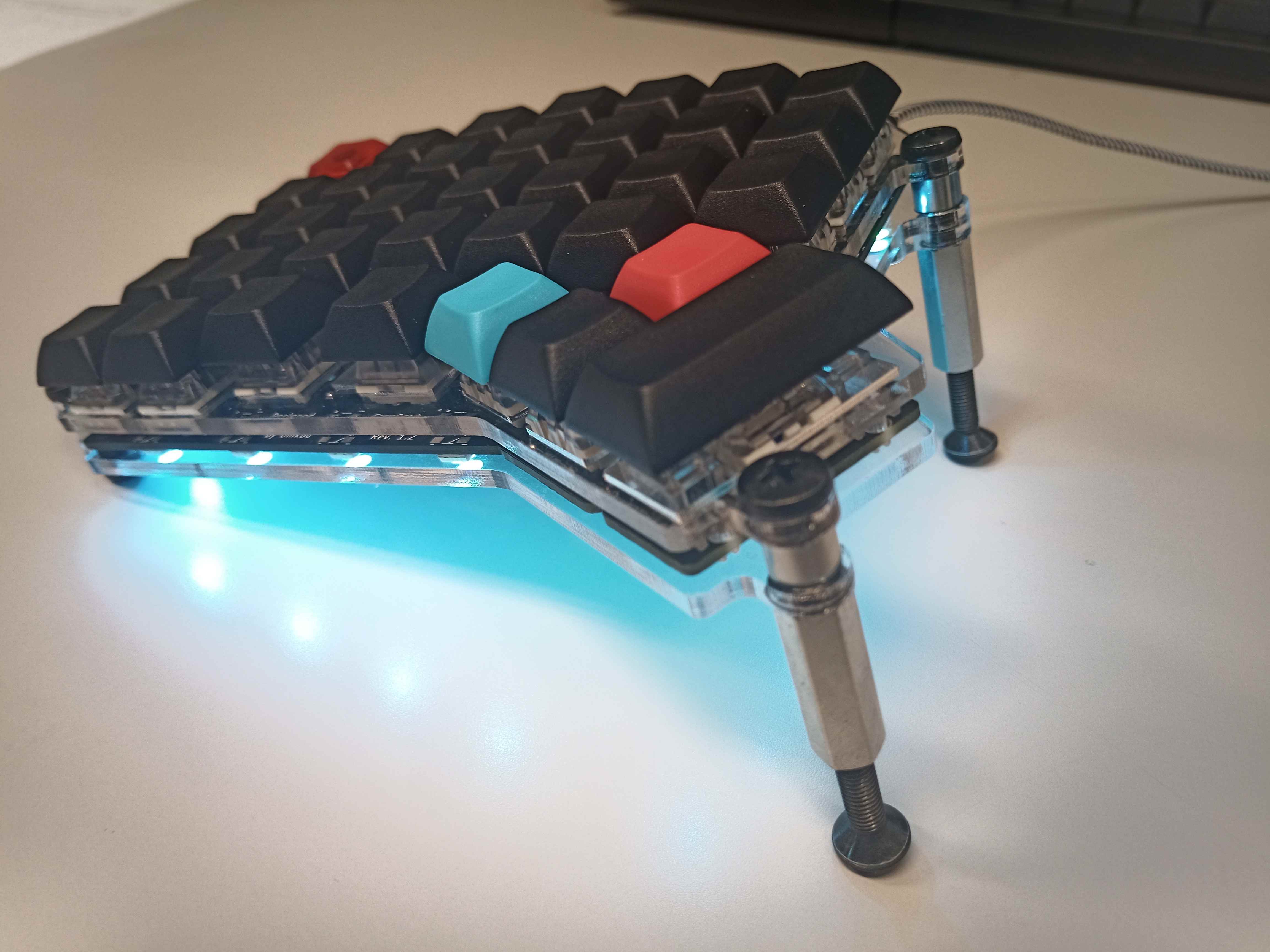
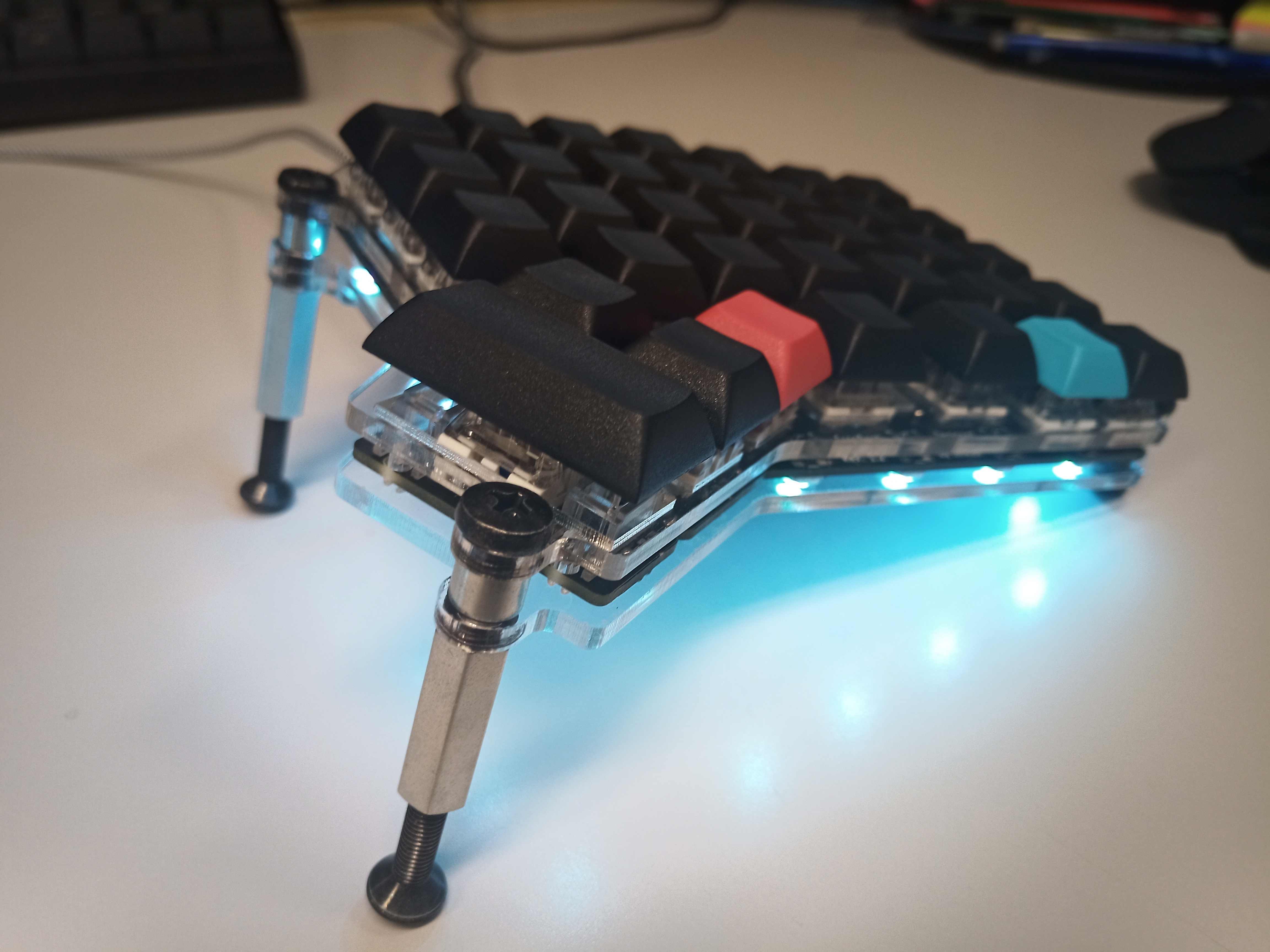
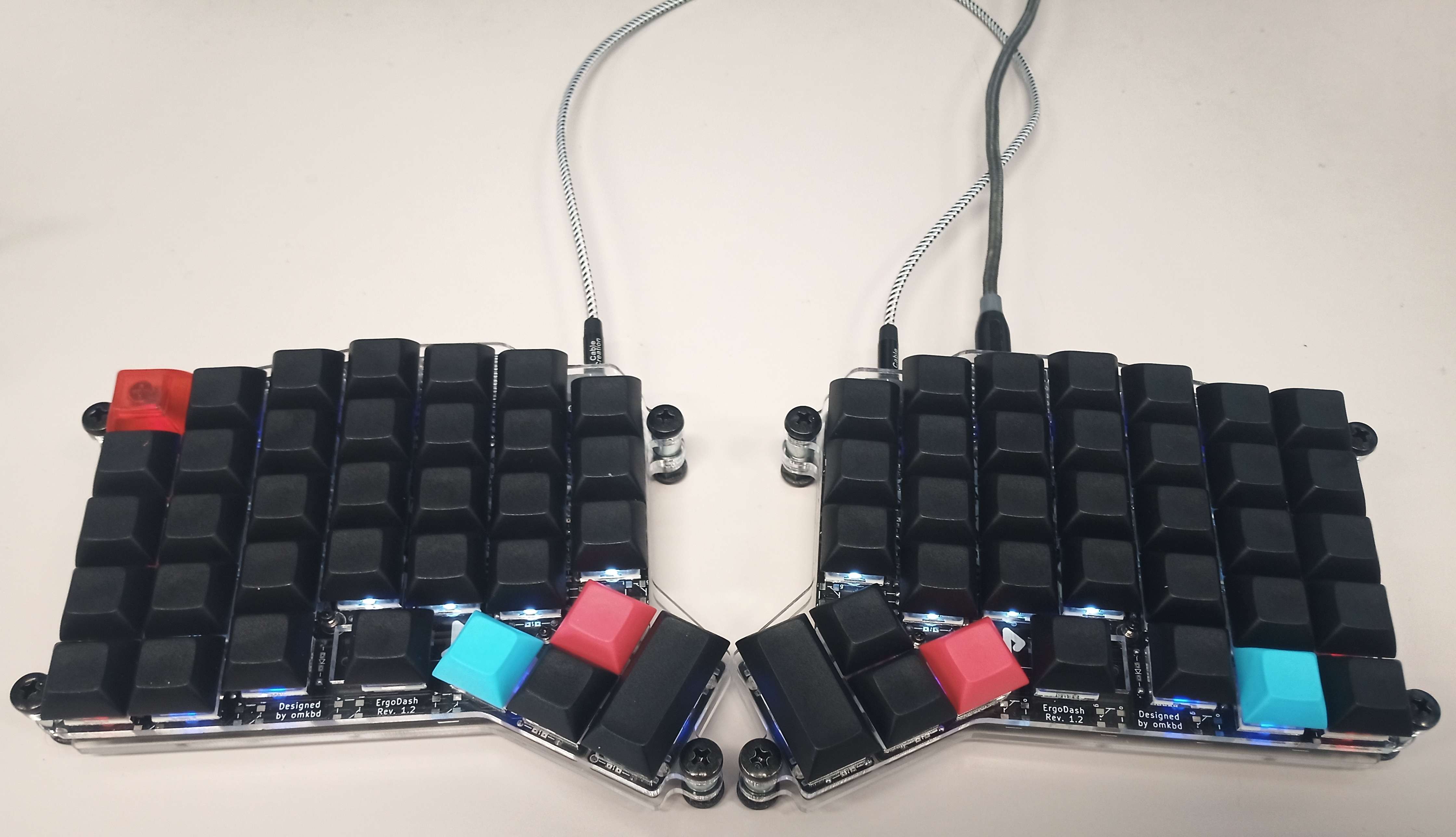
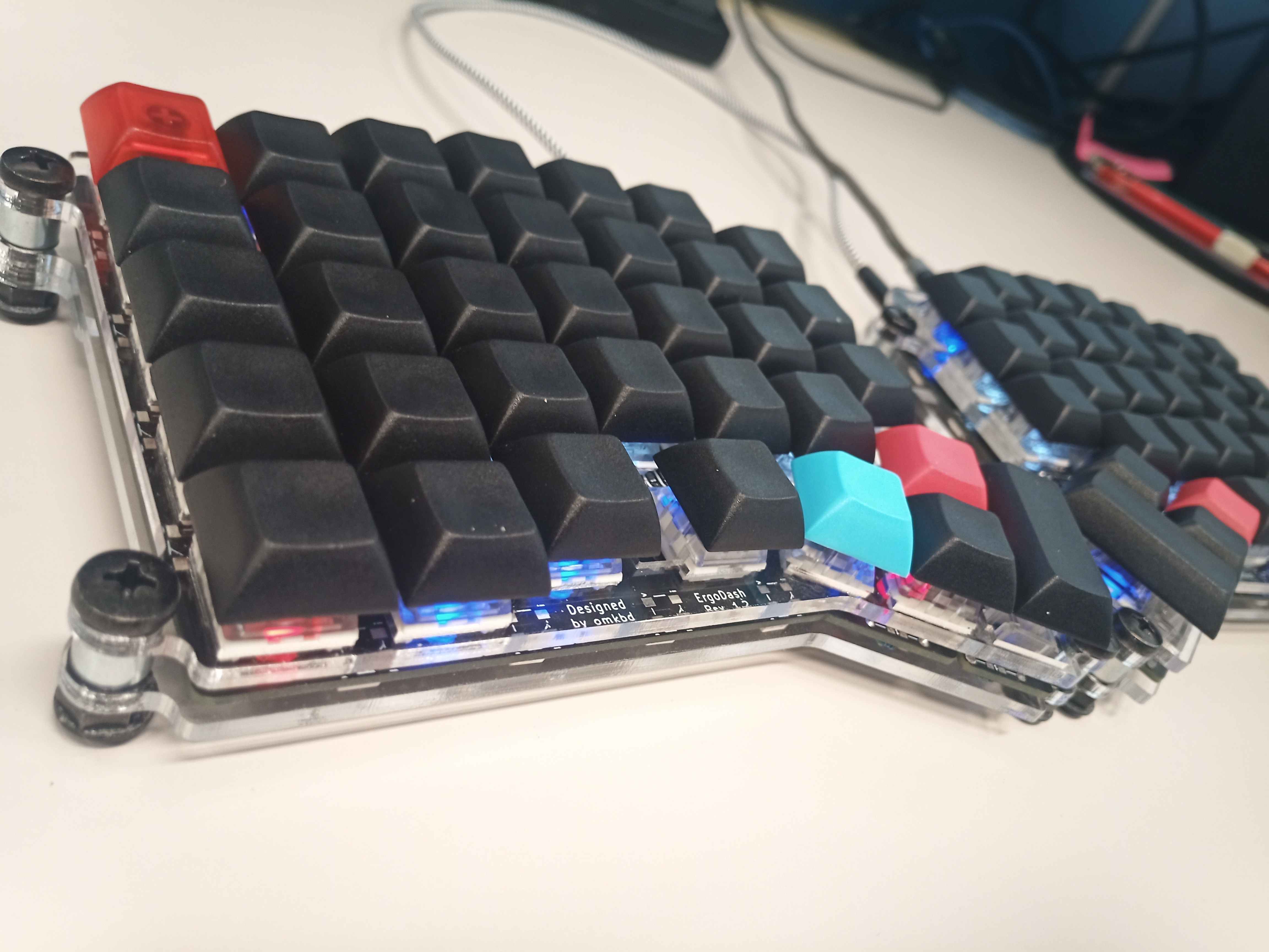
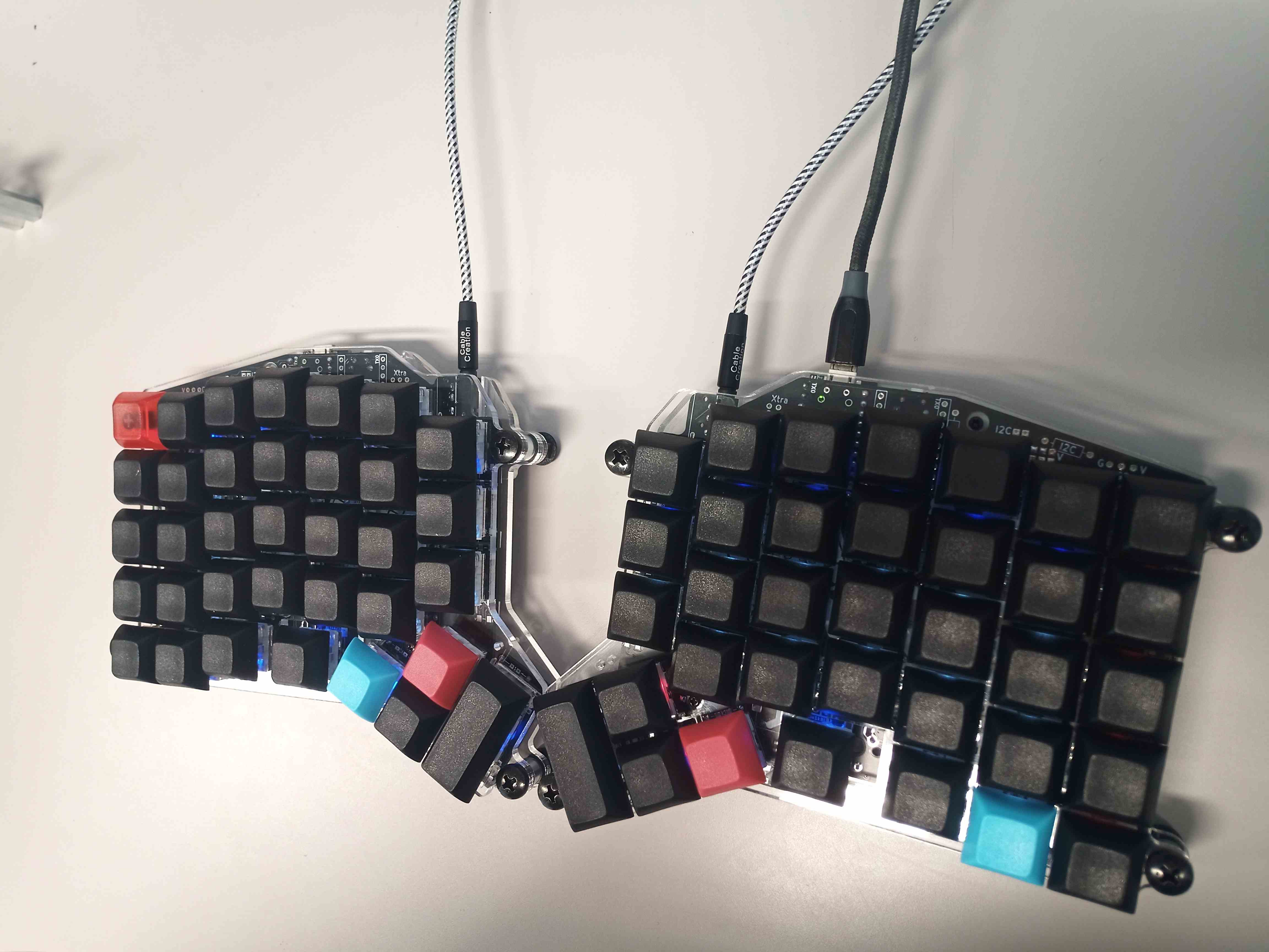
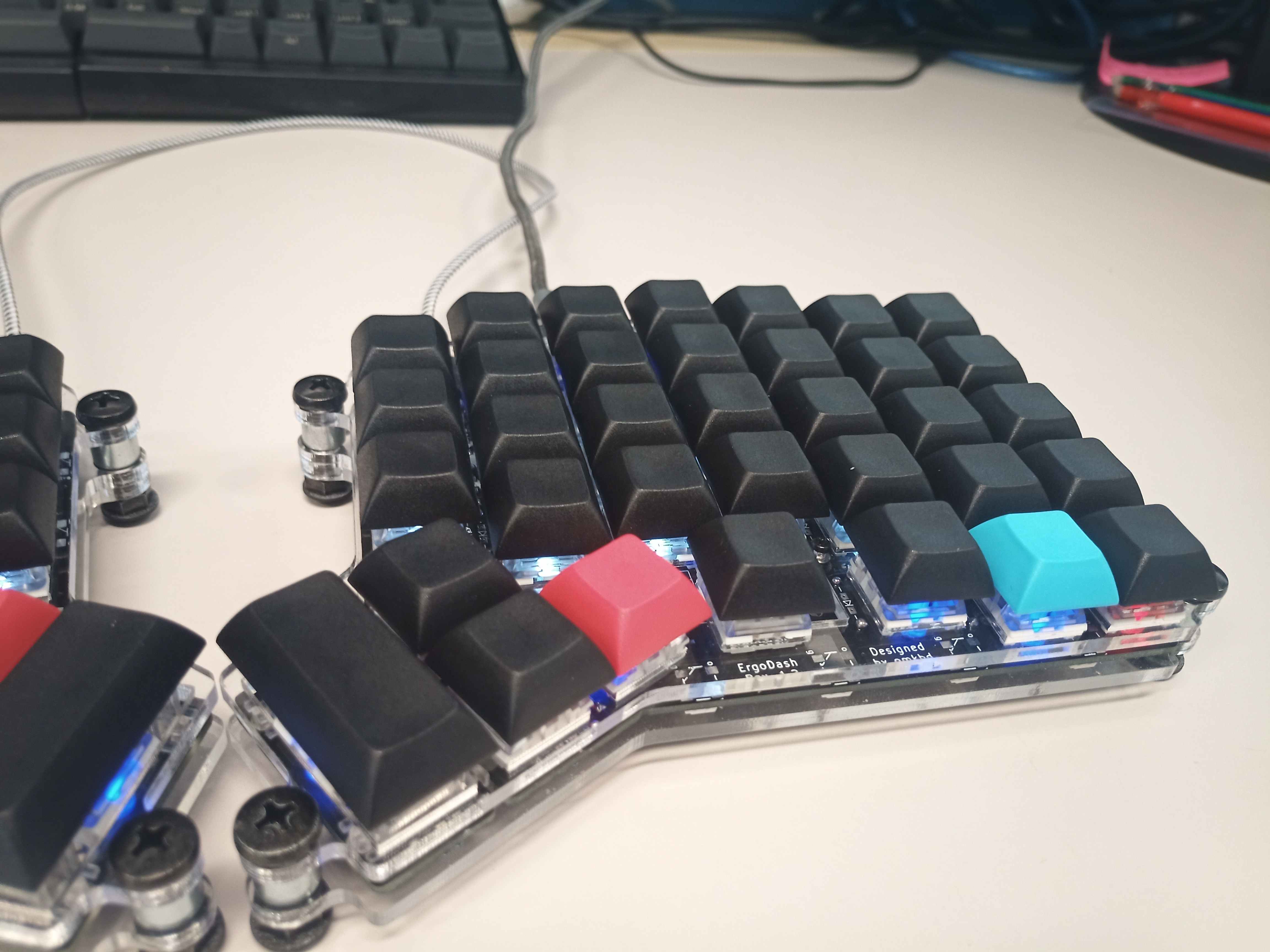
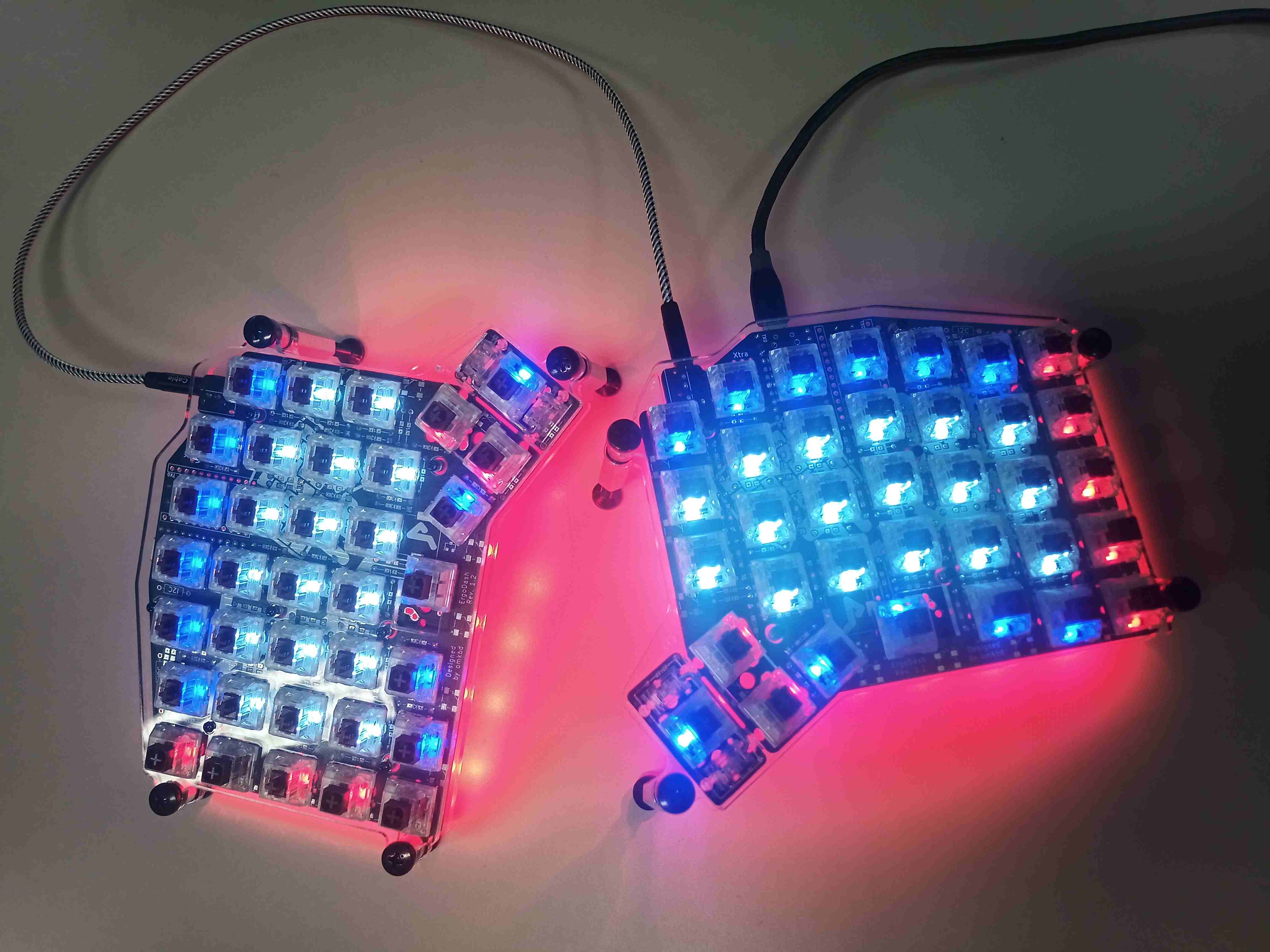
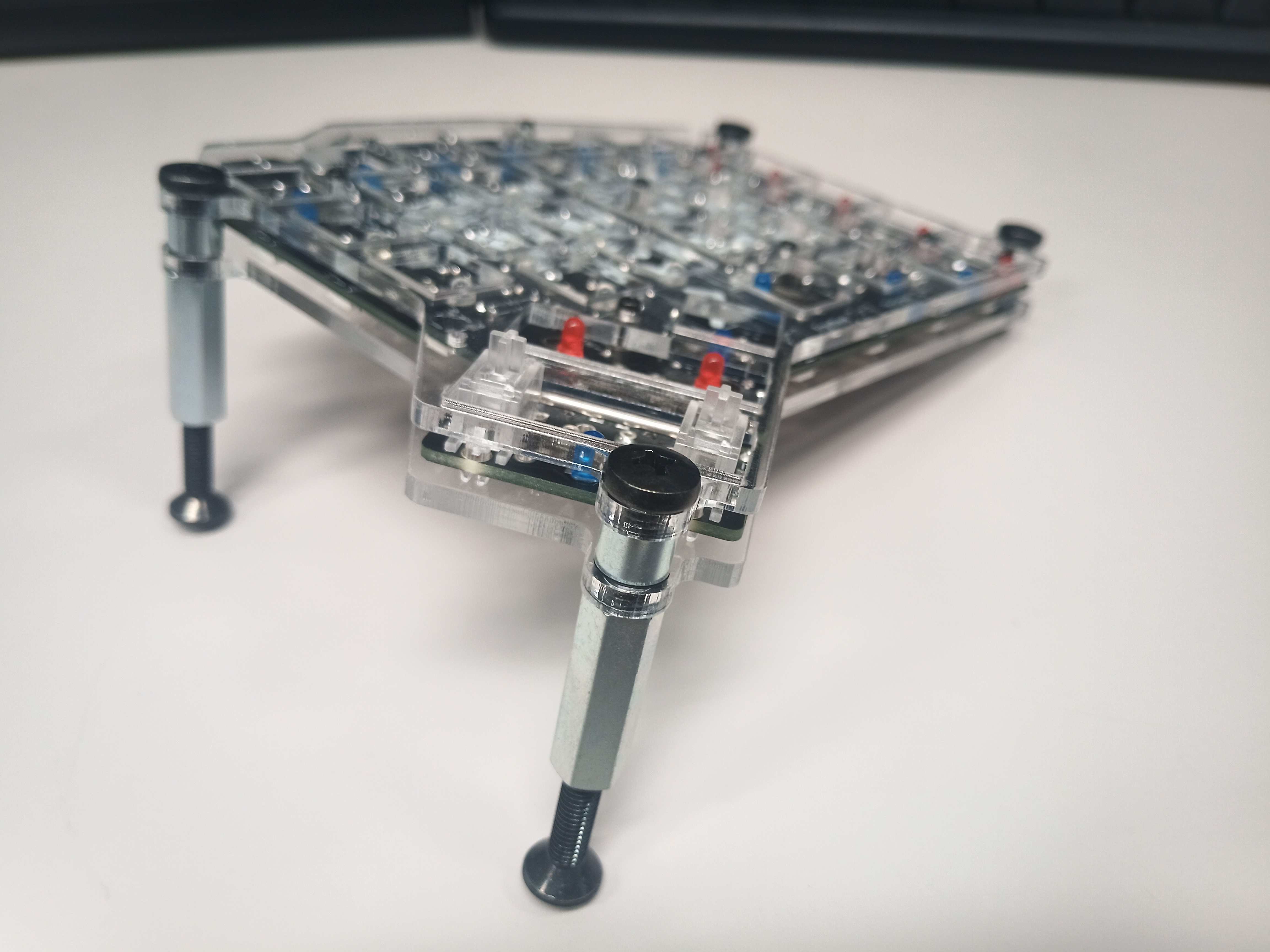
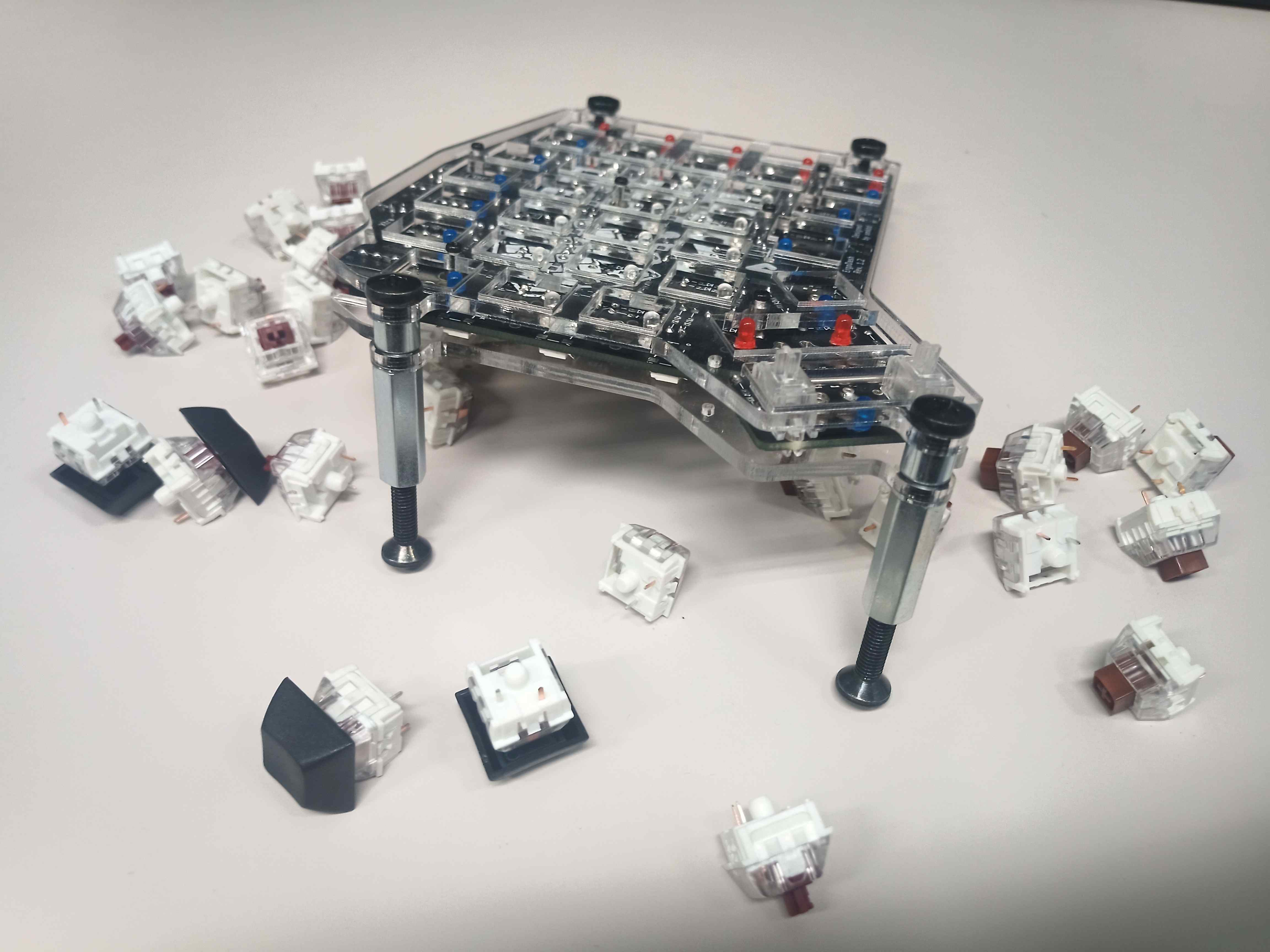
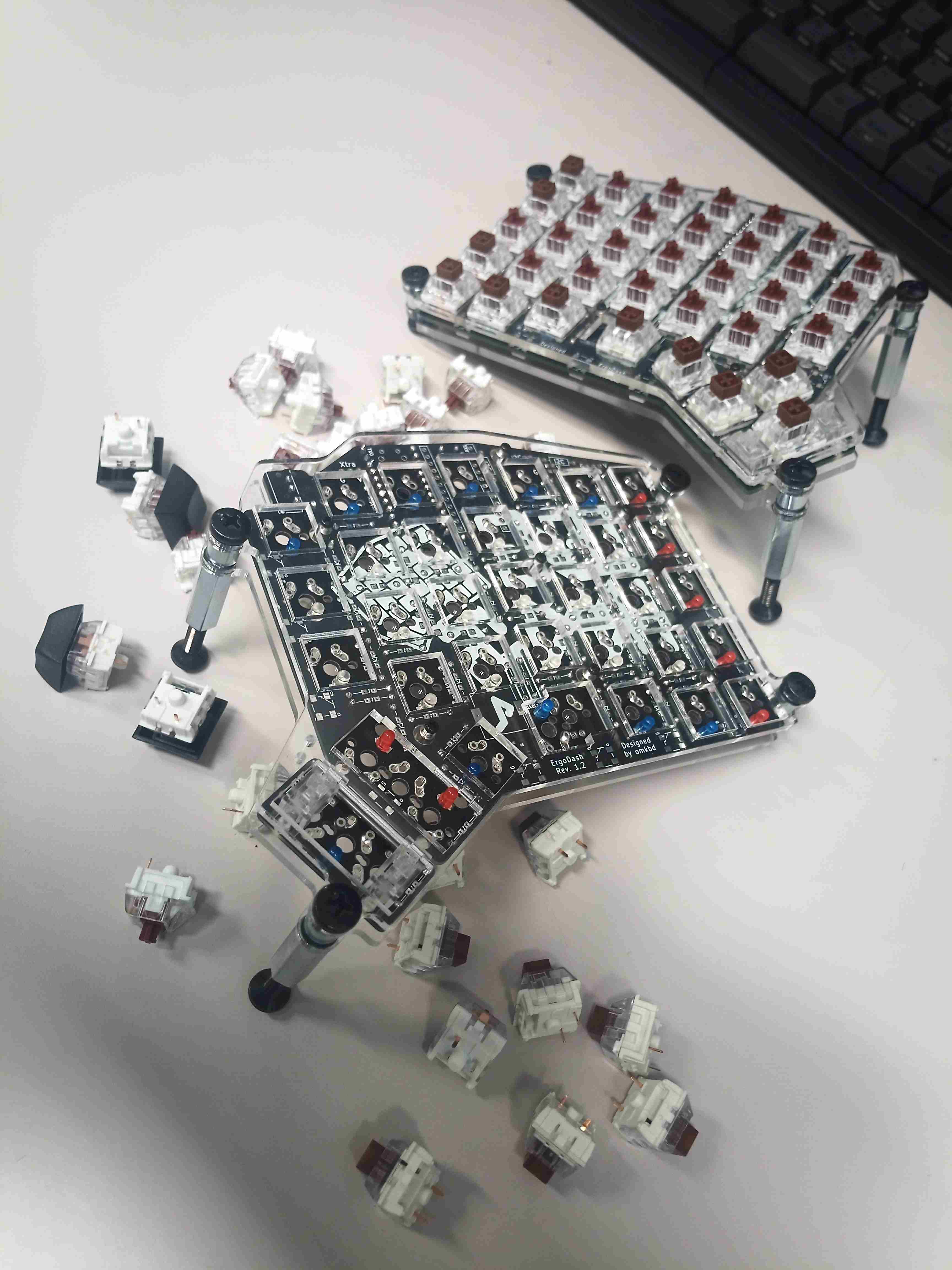
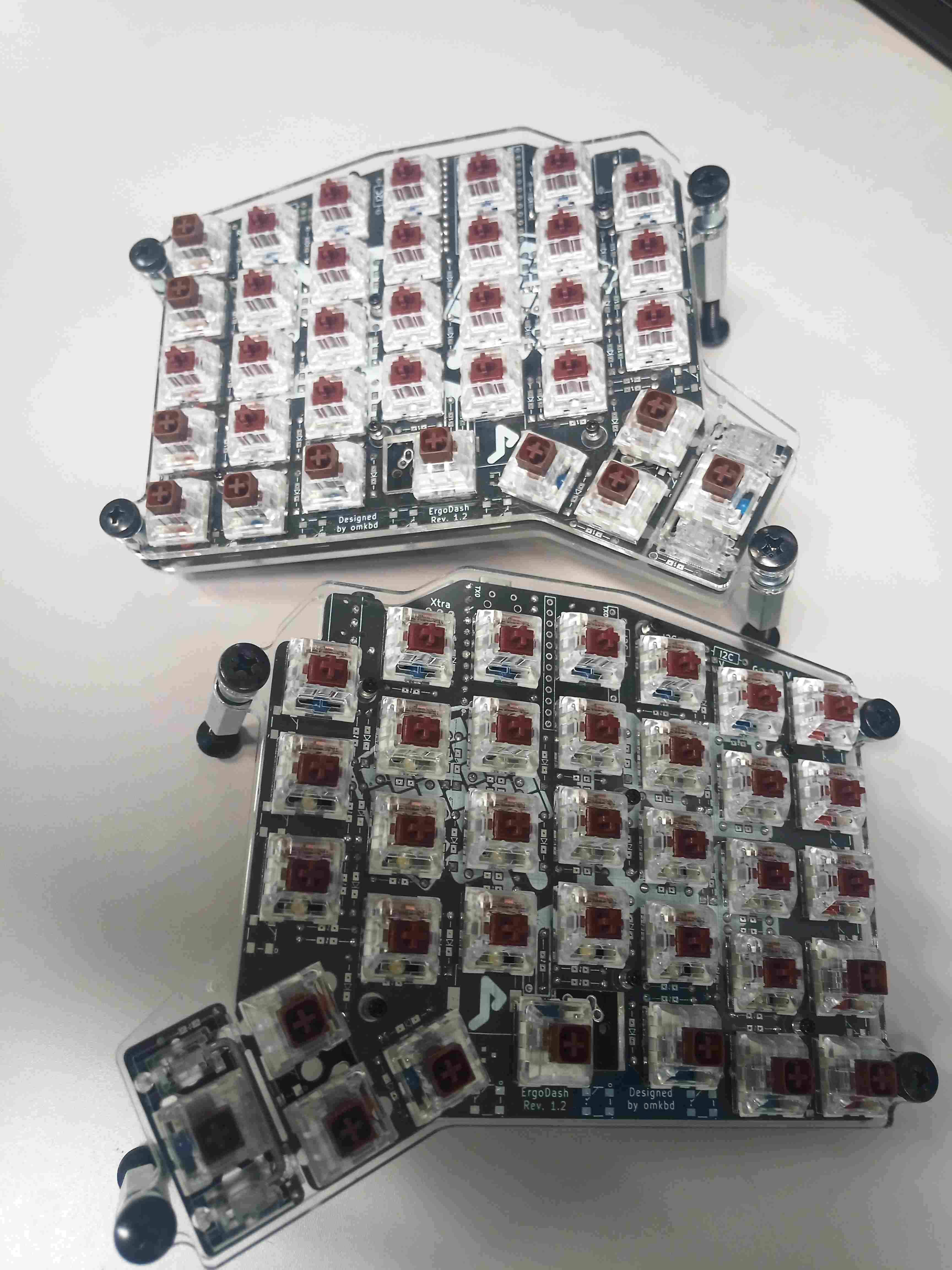
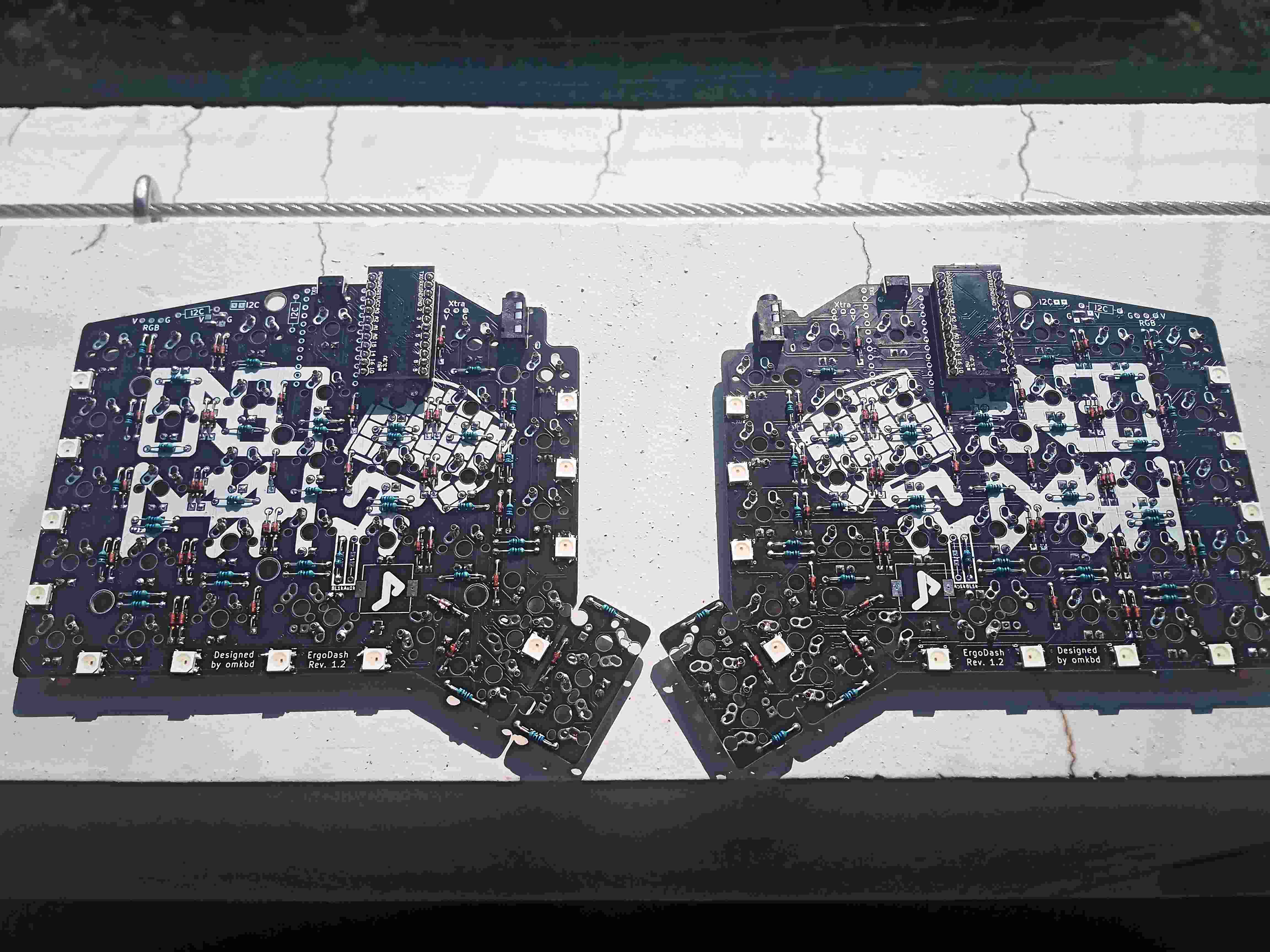
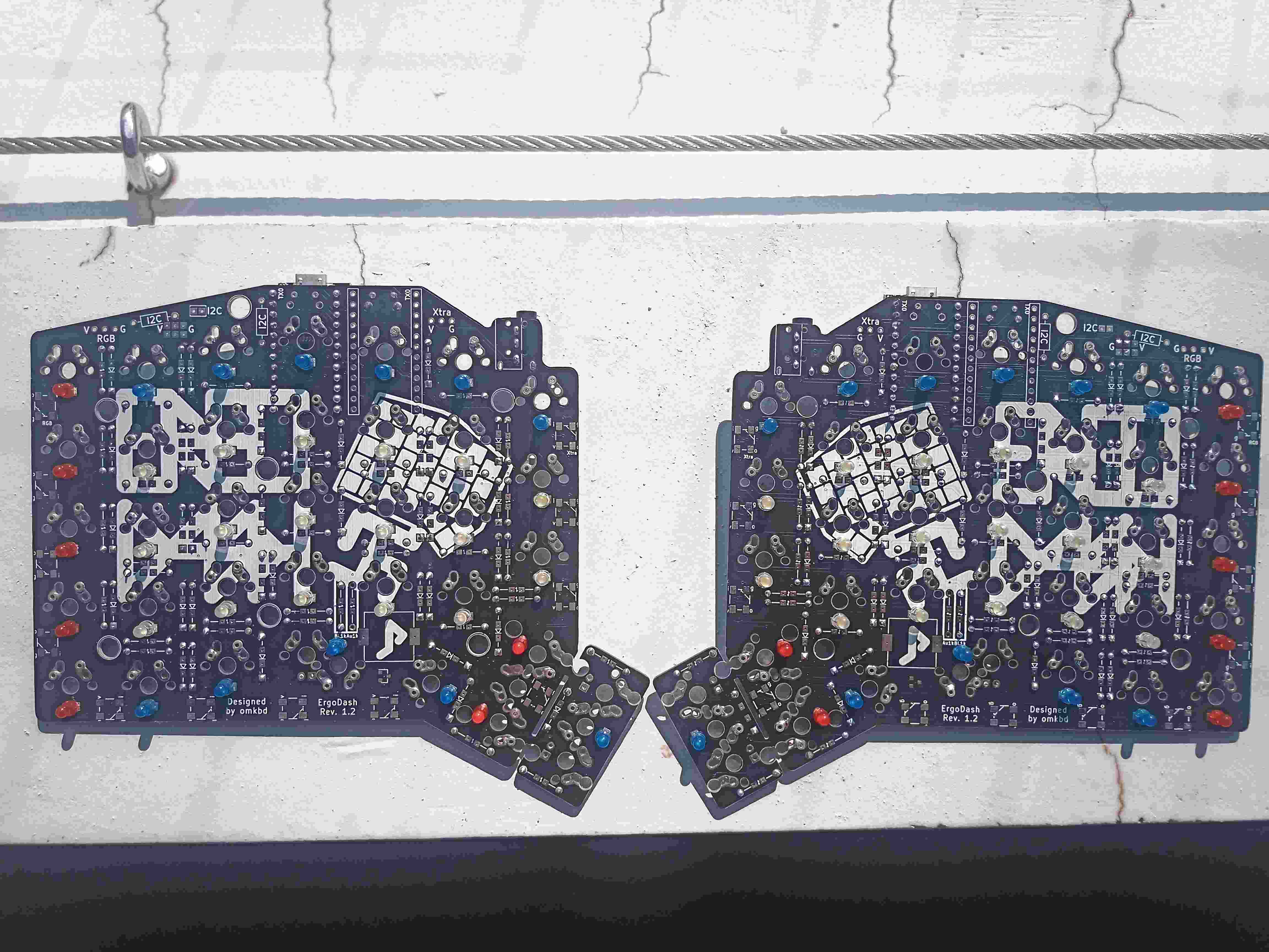
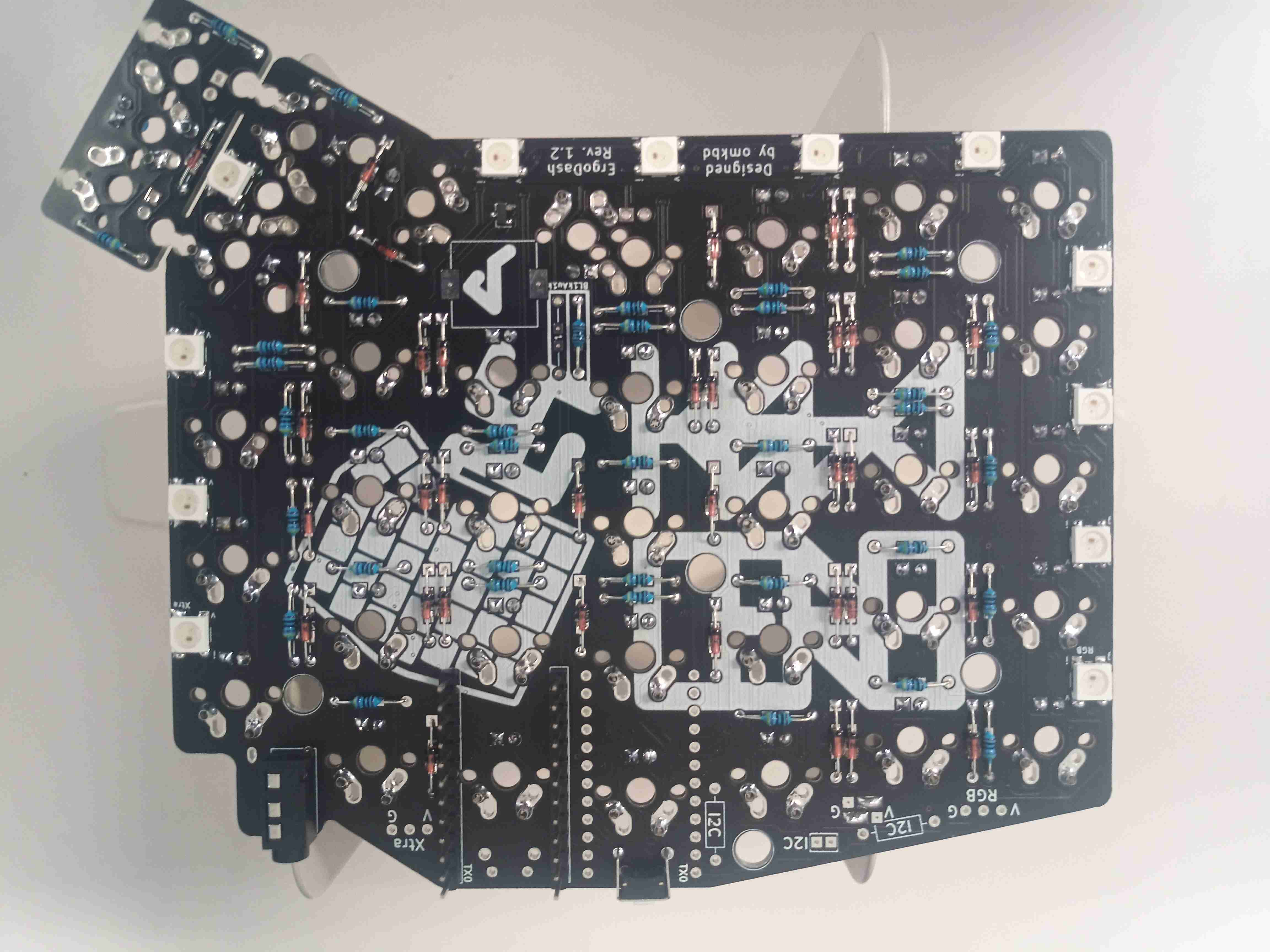
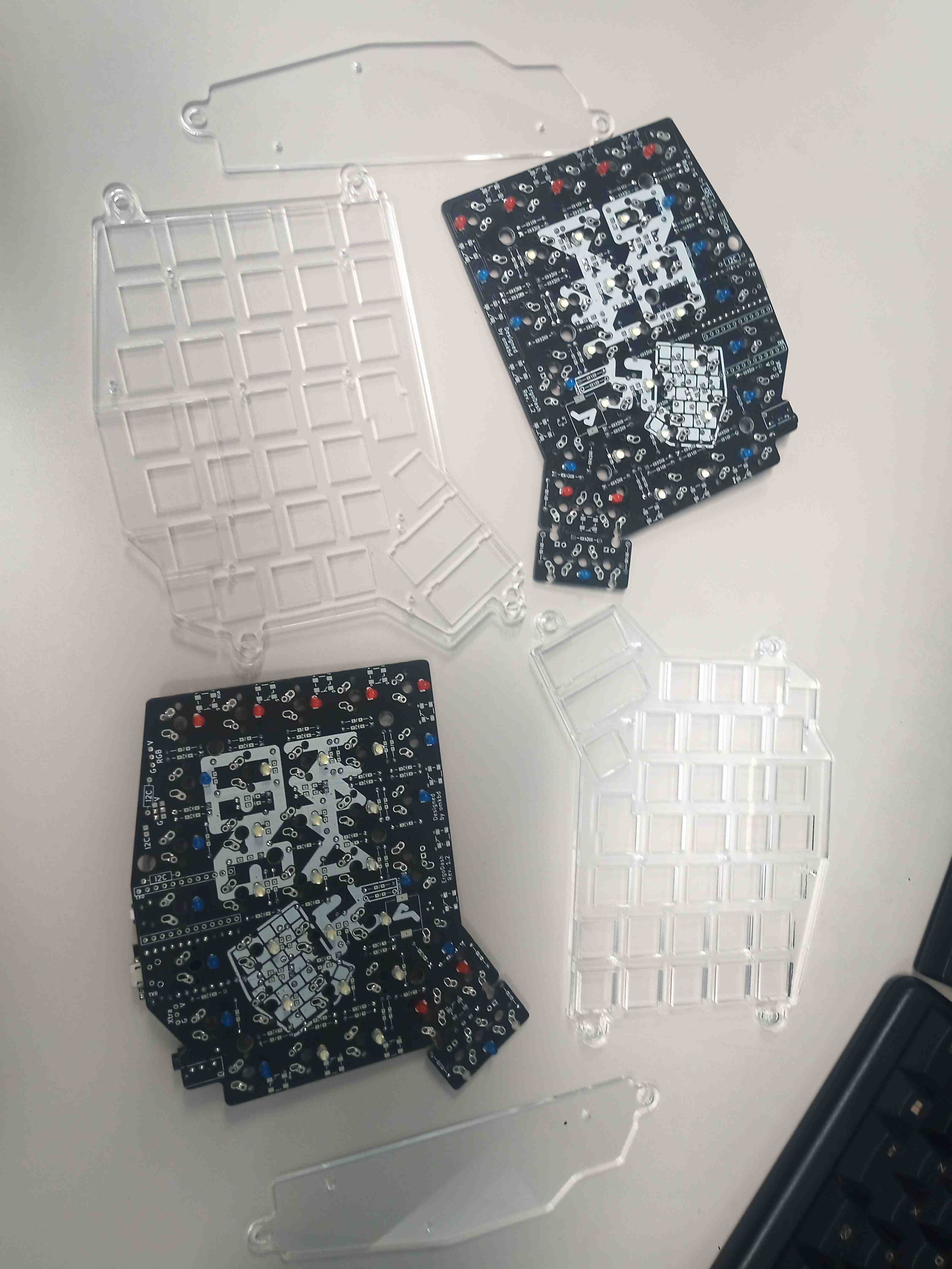
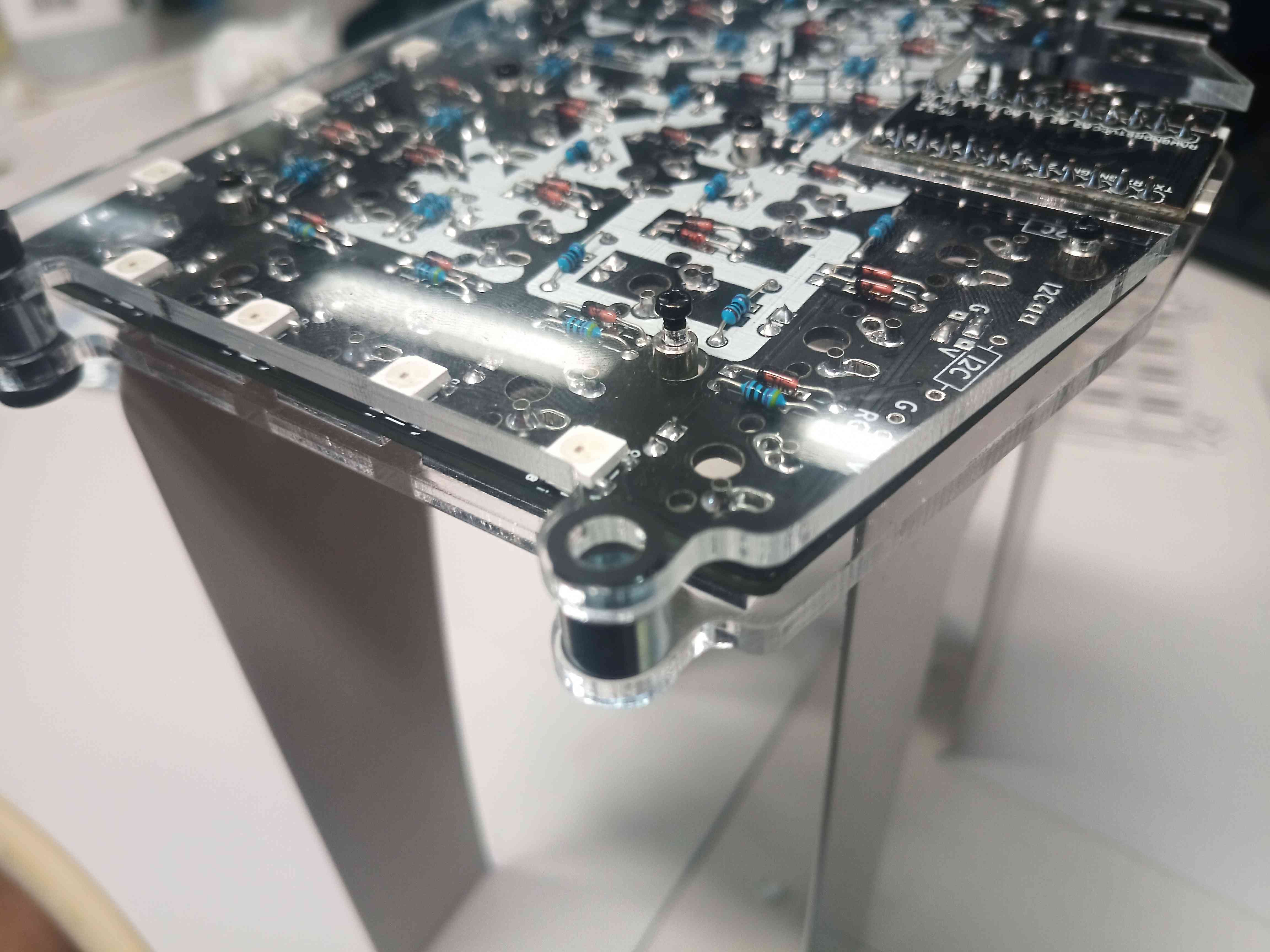
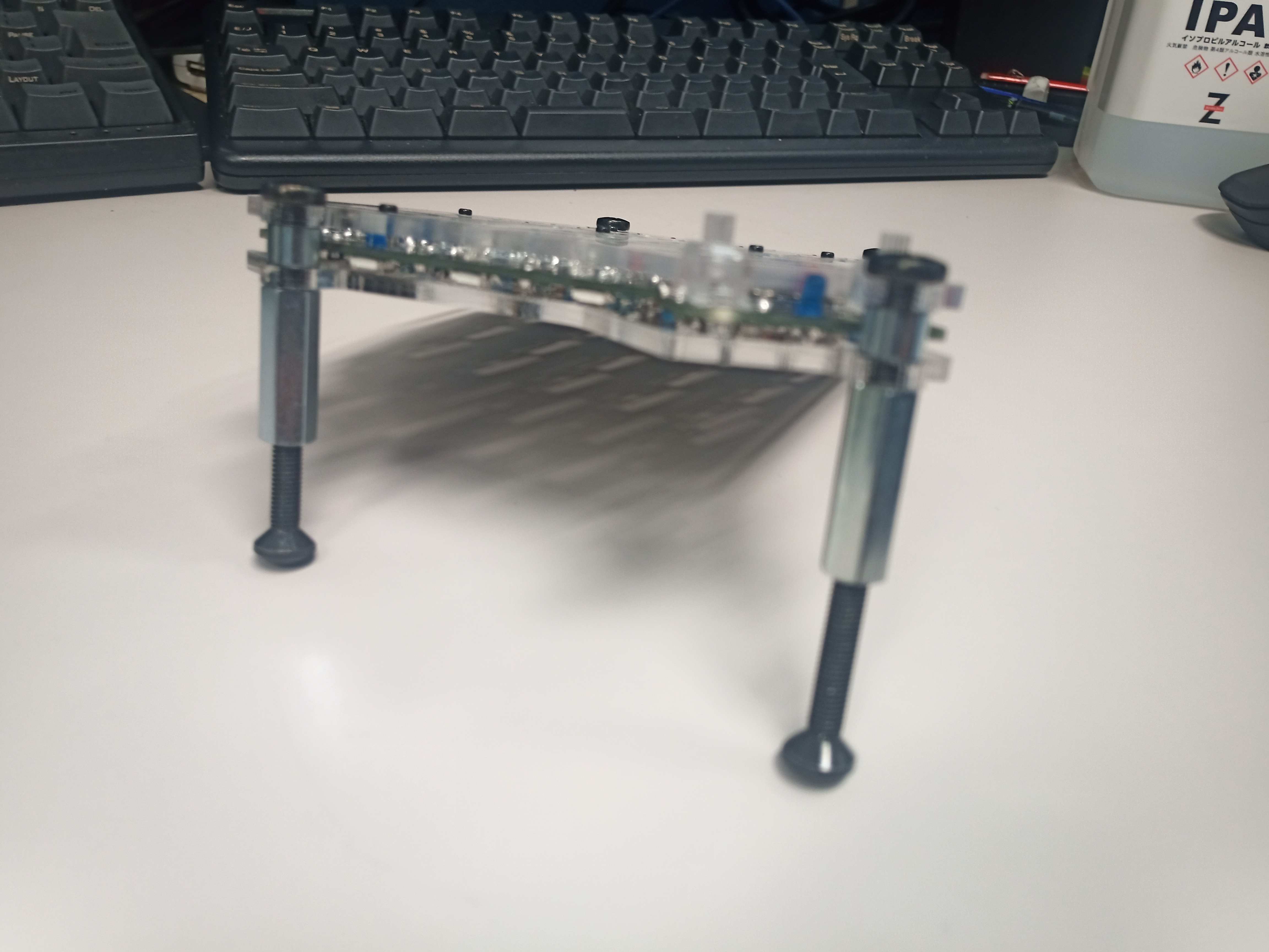
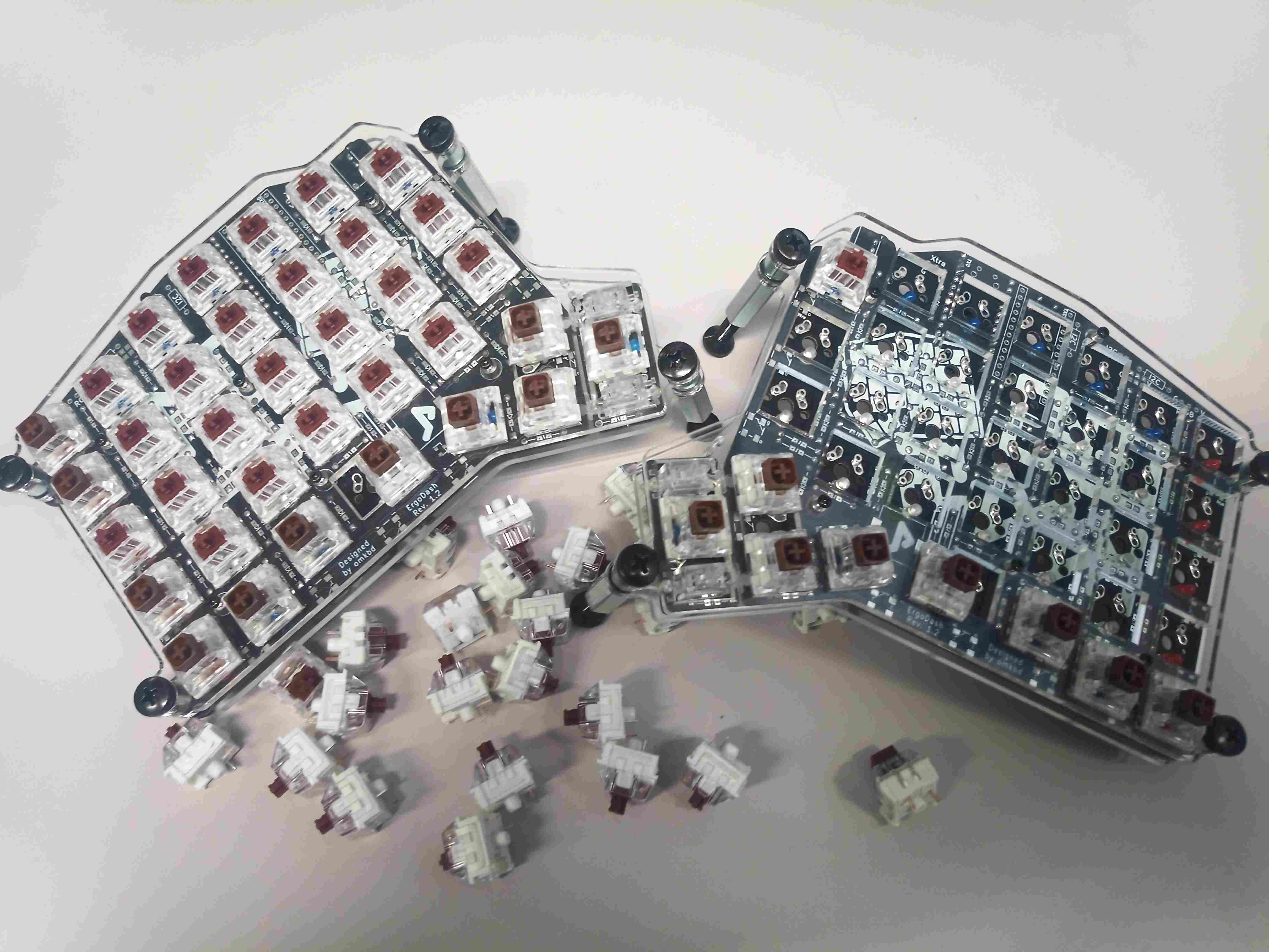
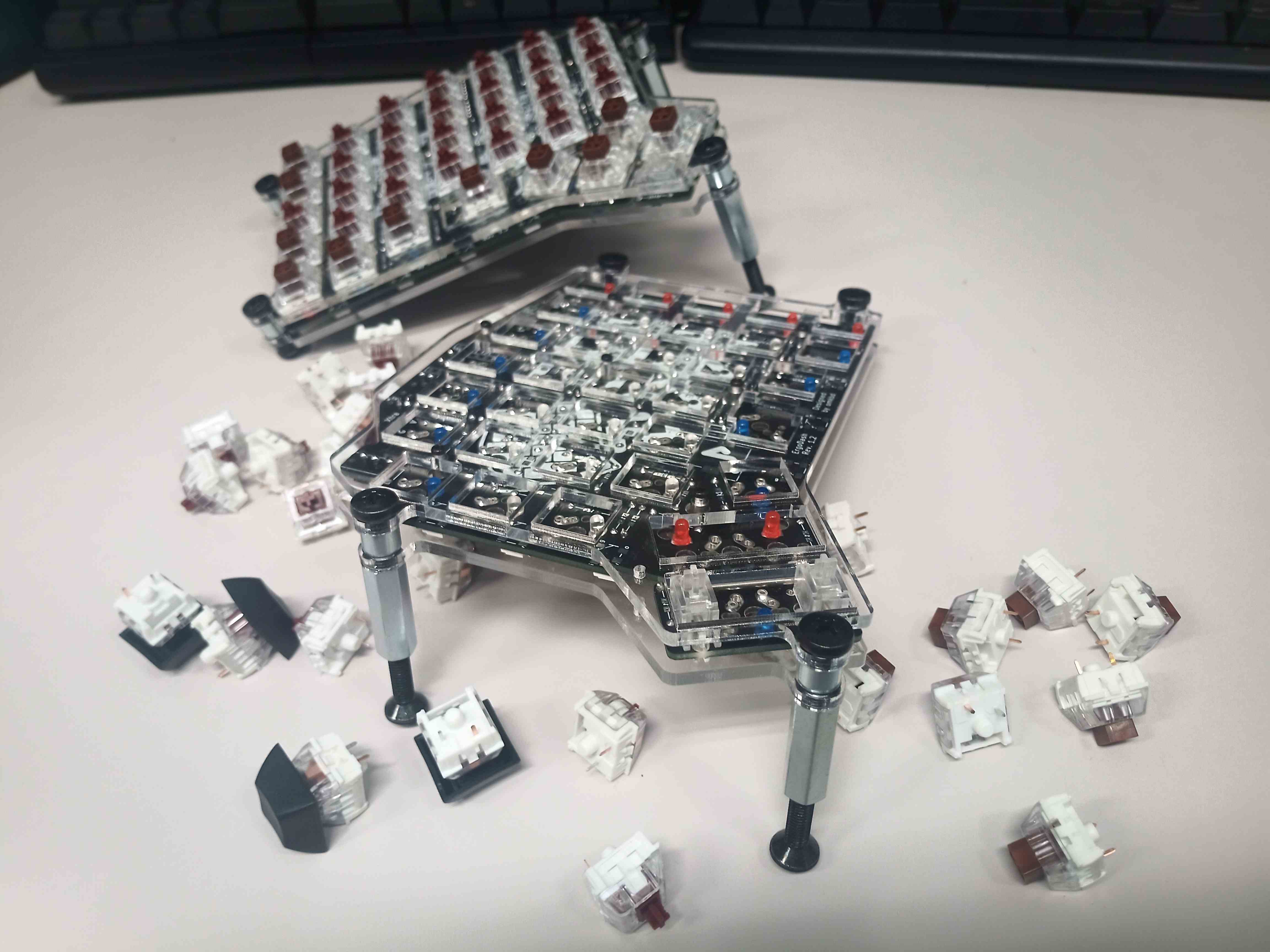
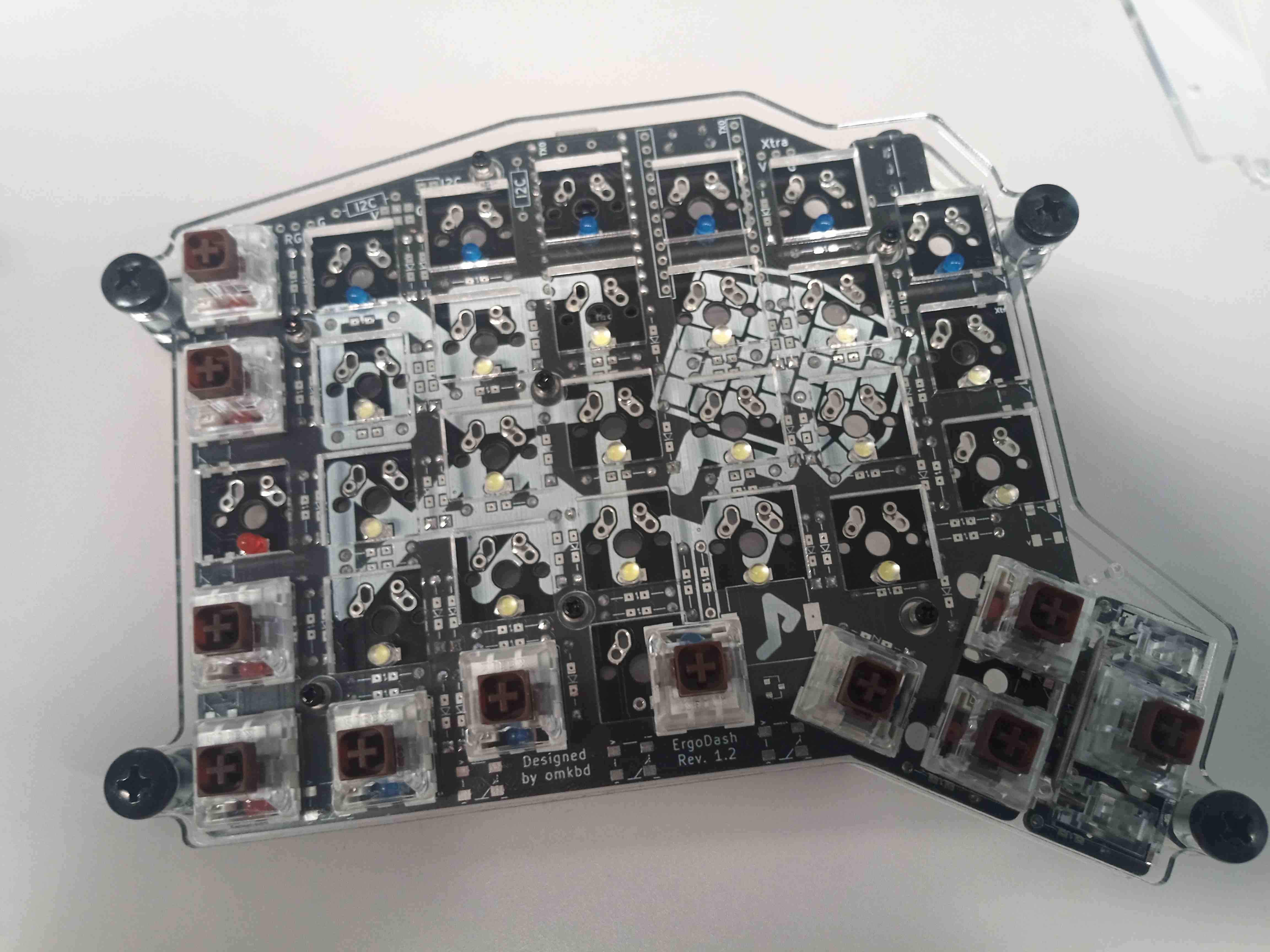
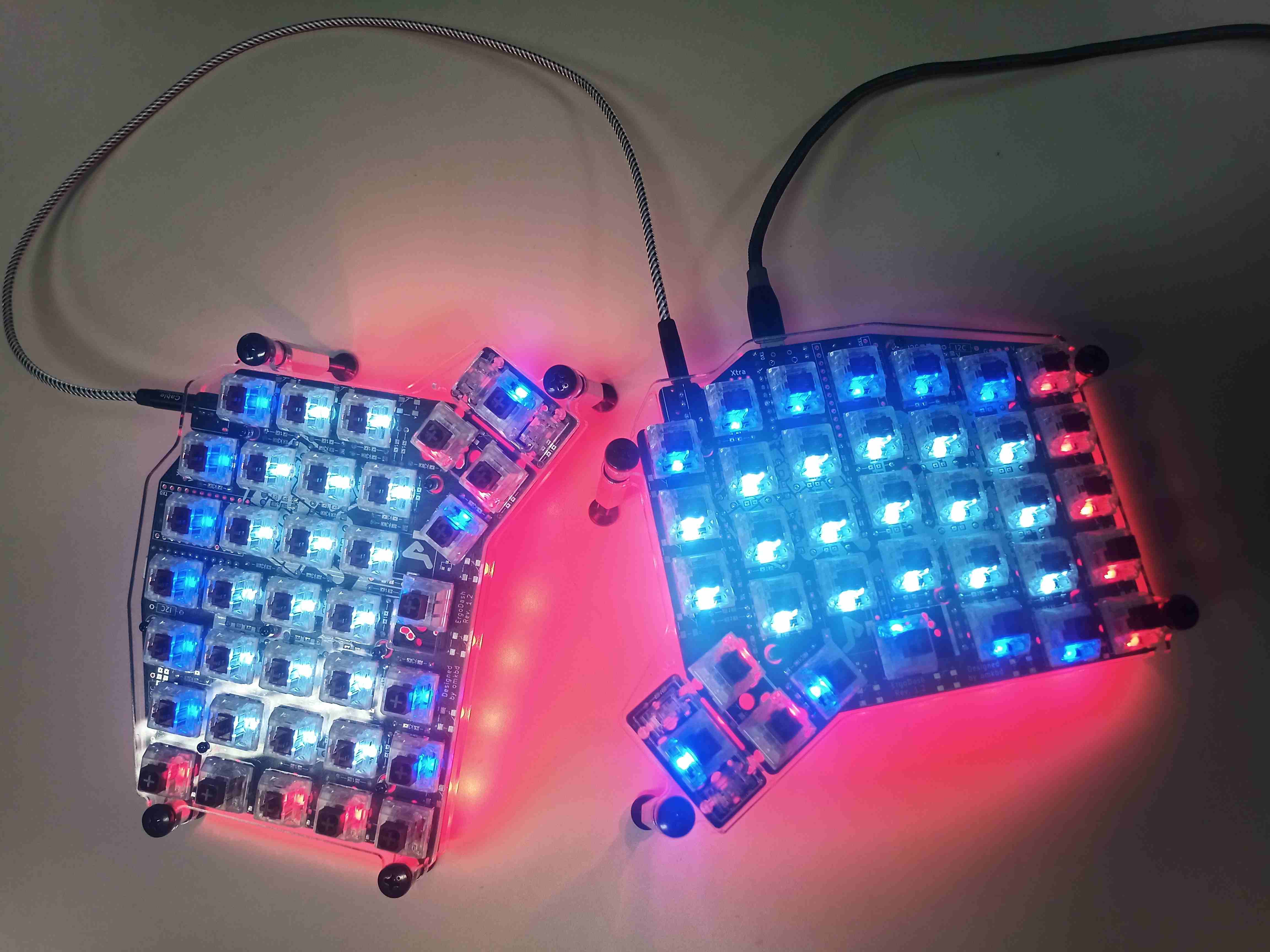
Pictures
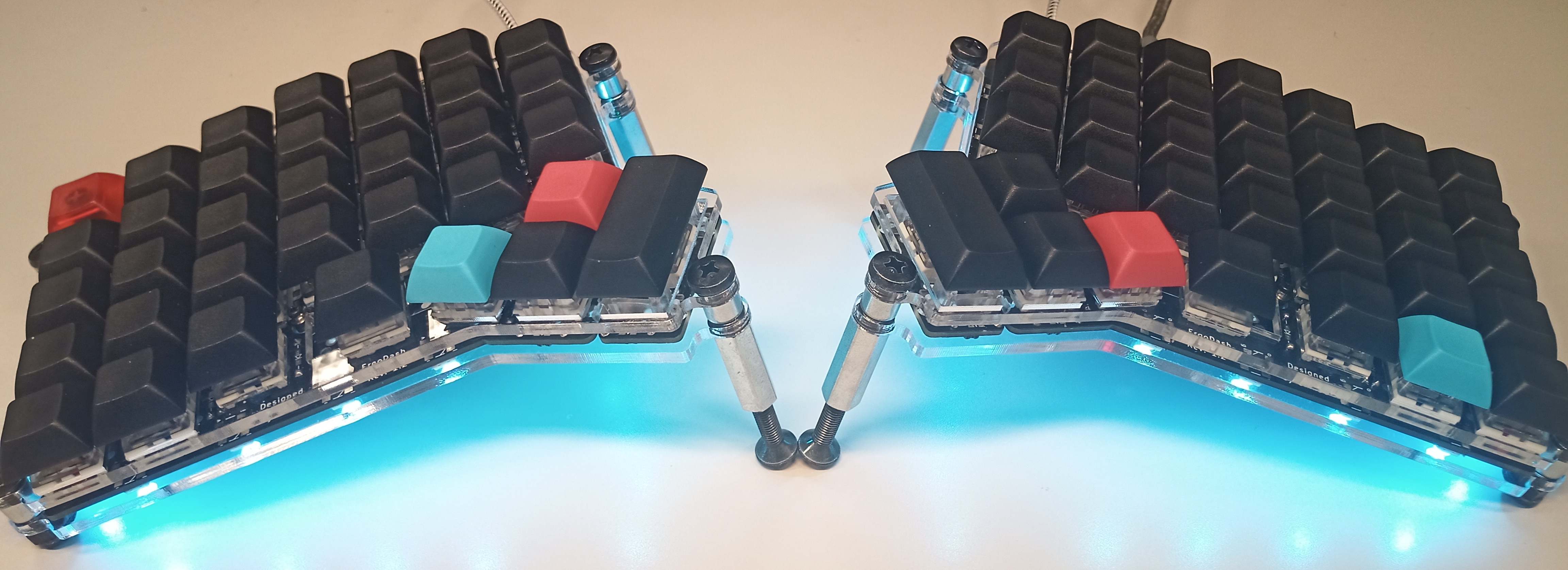
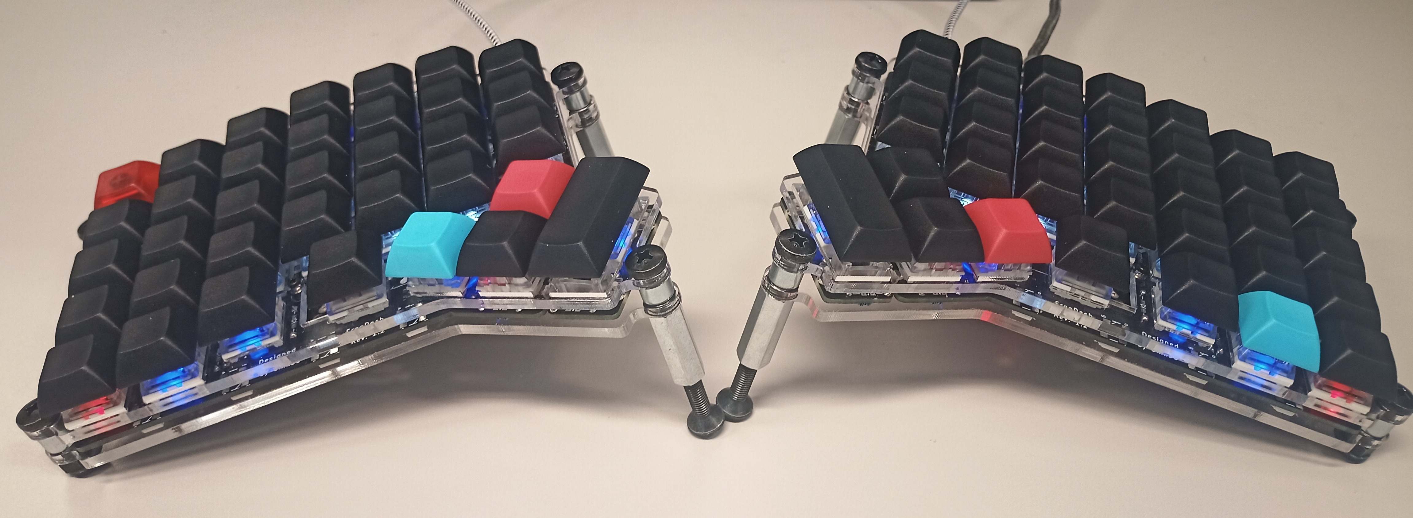
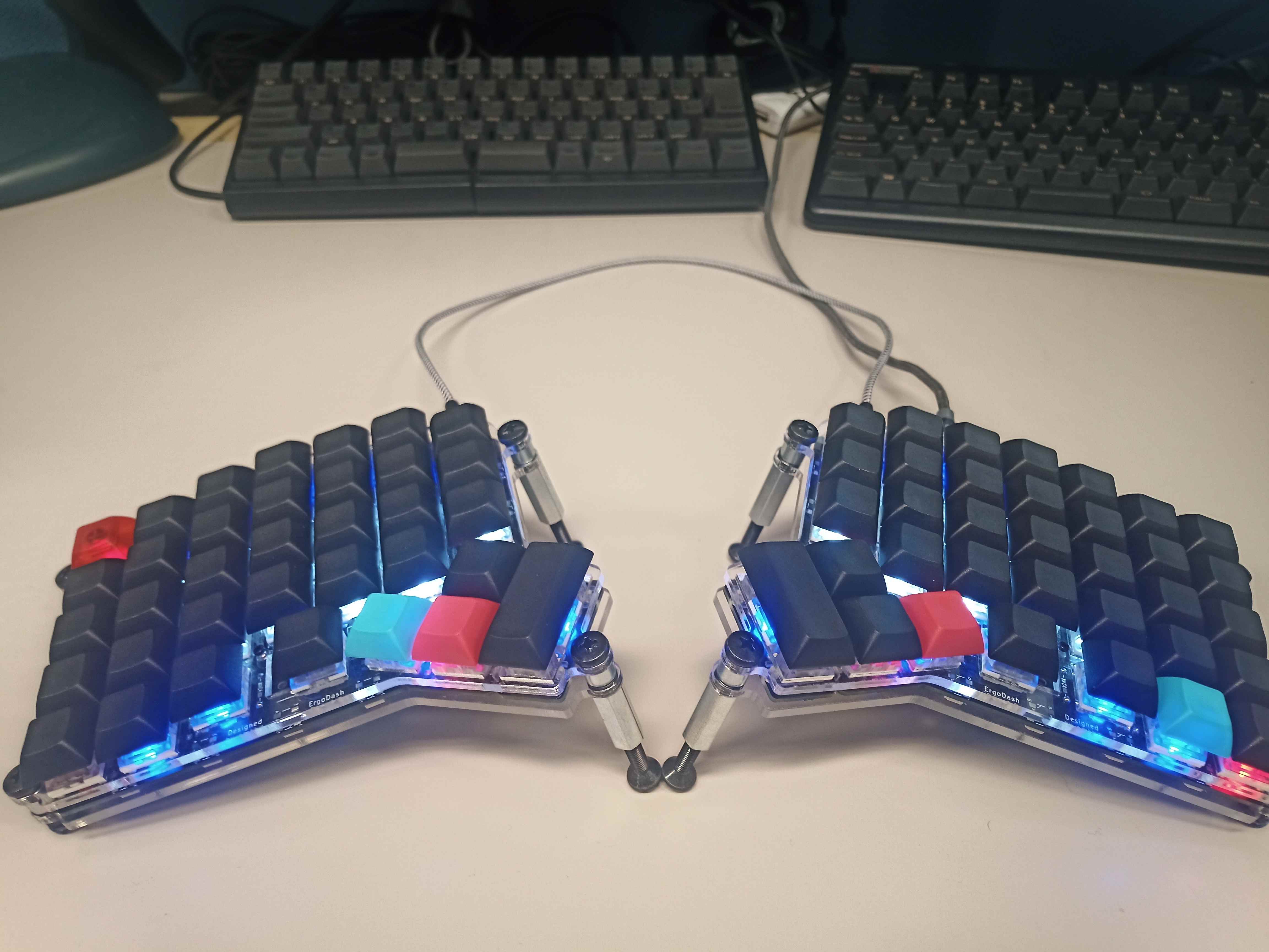
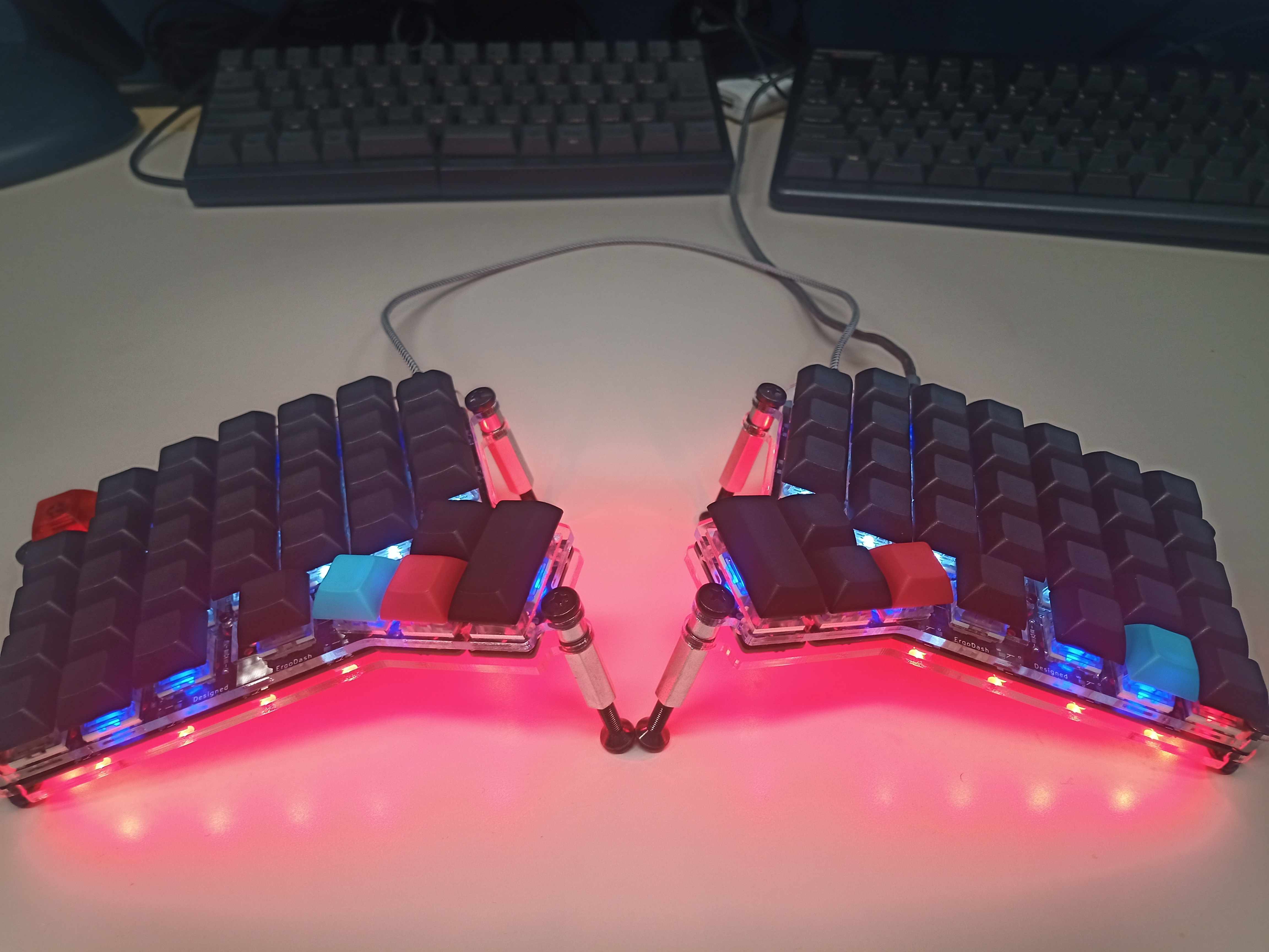
Specifications
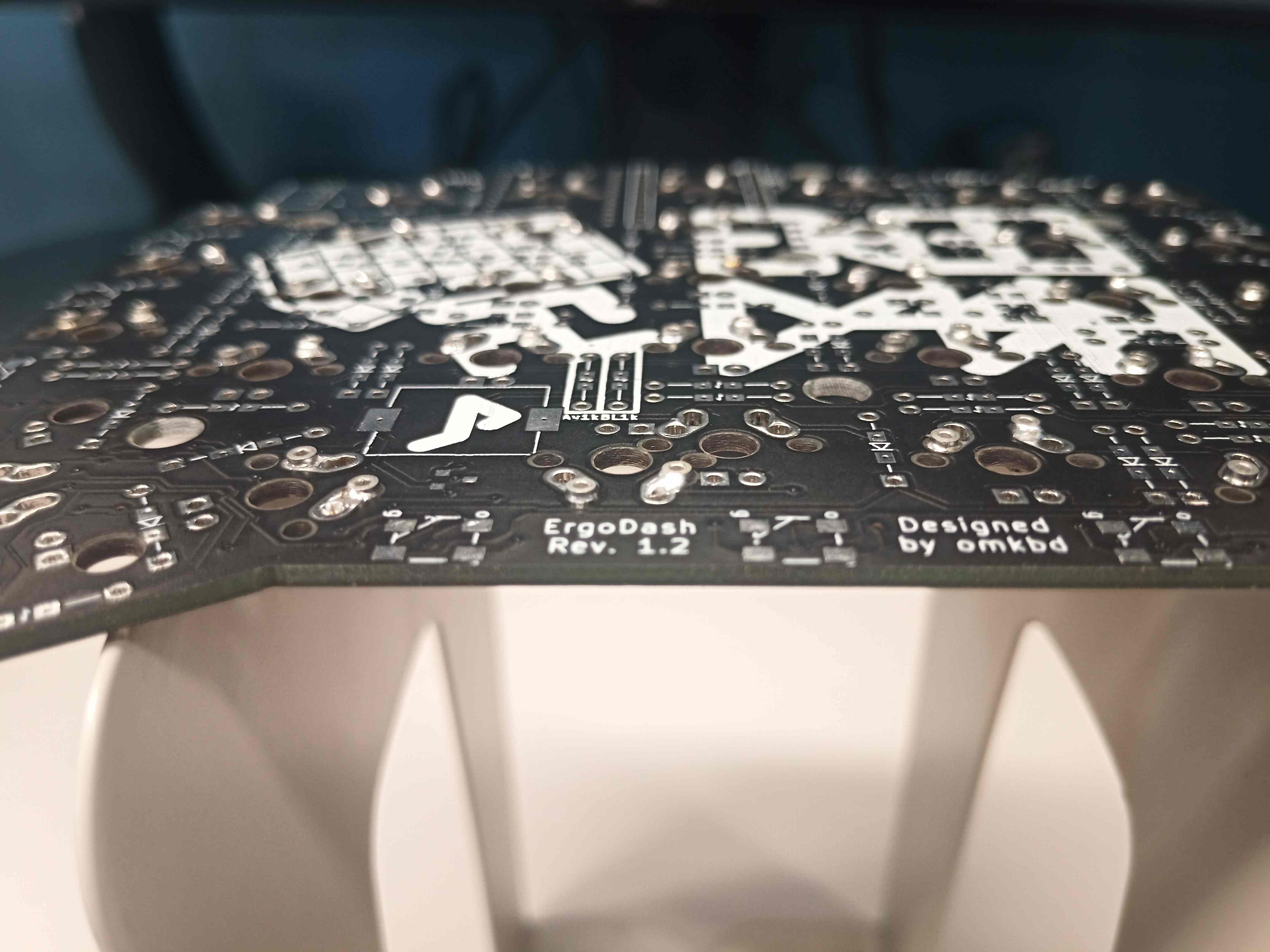
PCB: Ergo Dash rev 1.2
Case: Custom transparent acrylic case with tenting support (Original author, AI, DXF files)
Switches: Khail Switch Copper x 50, Khail Box Brown x 20
Keycaps: DSA PBT Blank Caps (68 x 1U, 2 x 2U)
Miscellaneous:
- Mill-Max 0305 receptacles for switch hot-swapping
- No stabilizers
- RGB LED x 24 for underglow
- Backlight LED x 70 (Red, Blue, and White fixed assortment)
- Set of screws, spacer/standoffs, and nuts for tenting
(Exhaustive part list below)
Pros
- Better leverage of the thumbs with 5 x 2 thumb key clusters, as well as 3 additional keys per index (no more moving the right hand to reach Backspace, Delete, Home, etc… keys)
- Improved workflow on i3wm Tiling based window management for switching between workspaces and windows (maybe subjective though)
- Split keyboard allows for better posture, with straightened back and shoulder facing outward.
- Less pronation with the tenting kit.
- Highly customizable keyboard layout via the QMK Toolbox.
- Reduced hand movement if properly combined with a trackball.
Cons
- Relatively expensive (but can shave off a bit by skipping the RGB and switch quality, and hot-swap feature). Hot-swapping and tenting are quite expensive (~35\$ each, then ~35\$ worth of screws, standoffs, and nuts, just imagine…)
- Learning curve that might take around four days for the alphabetic keys, and more for the numeric and other symbol keys.
- This tenting method is not as flexible as the original one, and might require a higher investment.
- Still need to move the right hand to reach the mouse. In retrospect, a trackball or trackpad around the right-hand thumb cluster would be ideal. Nevertheless, it is possible to enable mouse keys in the QMK firmware to serve a workaround, albeit a less precise one. (See Firmware Flash Notes). I ended up combining it with a Logitech M575 Trackball positioned under the right board, which tenting happened to fit just right.
For a more integrated keyboard, I would recommend the Charybdis, which build notes should also be accessible here.
Important build notes
- If not using hot-swap, the build order is really important, especially regarding soldering the switches, which requires to pre-install the upper side of the case. The Pro Micro covers the holes of 2 switches and their LEDs, so those must also be soldered BEFORE soldering down the Pro Micro.
When installing the Pro Micro, make sure it is not too elevated and the pins are trimmed to be able to close the case properly. From my experience in this build, not doing so ended up in a slight bow on the bottom side of the case.UPDATE: After breaking the USB port of the Pro Micros on both sides, I realized that it was incredibly hard to de-solder them. This ended up costing me both boards.- Highly recommend socketing the microcontroller (especially if Elite-C). This will allow easier repair, upgrade, or replacement if needs be.
From here onward is the long version, which, in retrospect, just reads like a huge rant and excuses gave to myself for this “purchase”, all disguised as a build log.
Long version: The Why
After serendipitously stumbling upon the Typeracer typing competition website, then on the Keybr touch typing tutoring website, it turned out that I was using my keyboard wrong all along. No wonder, since my typing skills were mostly improvised on the go, and deeply influenced by gamings habits (WASD looking at you …). Embarking a new journey to improve my typing by exercising on Keybr, it dawned on me that the typing experience could be drastically improved by switching to a more tailored keyboards.
First, the slight shift to the right of the keyboard keys, which seems to have been inherited from physical constraints that occurred during the design of typewriters appeared to be not necessary, and even counter-productive at times. Furthermore, the under-exploitation of the thumbs, at least on the Realforce keyboard that was my daily driver so far could be vastly improved upon with thumb cluster keys. For example, the Backspace, Delete, Home, End keys, the arrow keys, etc… would require to move the right hand quite far away. Furthermore, when using the i3 Window Tiling Manager, it is quite cumbersome to, say, switch between workspaces, windows, or switching input methods on the IME because it requires the use of the Meta key to doing so, requiring to often shift either left or right hand down to hit it. To put it simply, the standard keyboard layouts could be considered inefficient in those aspects, at least for my personal use case. Besides, learning about pronation that usually occurs during prolonged use, as well as the posture problem, namely the slightly hunched (and arched inward shoulder) position I would have to sit in due to the “flatness” and “centered” nature of the general consumer-oriented keyboard finally motivated me to look deeper into the matter of customized keyboards.
After immersing myself in the awesome community of r/MechanicalKeyboards and learning more about mechanical keyboards from scratch, the image of the ideal (at that time) keyboard slowly started to form in my mind. Namely, it had to be (1) a split keyboard, (2) with enough thumb cluster keys to map the Meta and Layer keys, and (3) tilting and tenting support to reduce pronation and allow for a “straight back and wide shoulder” position while typing. Turns out that besides the potential benefits cited above, customized mechanical keyboards can also result in faster-typing speed depending on the switches installed, and allows for in-depth customization of the key layouts via firmware editing and flashing.
Other reasons would be the itches that slowly crept into my hands, as I sat in the “ivory tower” for more than 3 years straight, without using my hand to realize something that physically exists in the real world. Another would be my childhood dream of soldering all day long to build some electronic devices. This was also one of the motivations for adding all that RGB “bling-bling”, as I originally aimed to spend the minimal amount and passing over the lightning components. In retrospect, I got the opportunity to solder to my heart’s content, ad nauseum, and gain quite some experience via salvaging of the many mistakes that occurred, so I have no regret. Furthermore, I can still turn off the LEDs with a few key shortcuts (props to the QMK firmware which has a solid implementation of RGB modes by the way).
Looking around the various split mechanical keyboards building kits available where I resided at the time of writing narrowed down the choice to the Iris model, While learning about mechanical keyboards in general, a few more features happened to crawl up and latch down into my mind. Namely the ability to hot-swap switches to further improve upgradability, which was mainly inspired by this Reddit post. The tenting and tilting of the case was also a feature that was further consolidated after watching getting acquainted with the ShortCircuits (Linus Tech Tips) channel’s Dygma Ergonomic Keyboard Review, the ErgoDash custom case with tenting and tilting support of @clomie, and finally this アメ_ツチ_ホシ_ソラ Custom Iris tenting.
[2022-05 UPDATE]
After around two years of usage, the USB ports of the Pro Micro controllers on both sides broke. Unfortunately, it was nigh impossible to de-solder the Pro Micro to fix them. Through the process, both boards ended up unusable due to too much force applied to them during the attempt at de-soldering. In retrospect, it could have nevertheless been possible to do with a high enough (de-)soldering experience. Lesson learned.
Since the boards could hardly be fixed, I ended up ordering a new set. This time, however, I decided to upgrade to the Elite-C as the microcontroller, instead of the Pro Micro. Namely, the rev4’s USB-C was designed more robustly to avoid the exact problem of the ports yielding that happened with the Pro Micro. Although at least twice as expensive, it does come with USB-C and maybe a better feature overall.
Additionally, instead of directly soldering the Elite-Cs once and for all to the new boards, I happened to learn about micro controller socketing and thus went for it. Socketing the microcontroller would allow for easier repair of the keyboard if need be or re-using the same microcontroller in a different build.
As I write this update, the Elite-C currently installed in this ErgoDash will be transplanted to Charybdis, which posts is also underway. Although the sockets for the micro-controller themselves might come as a bit pricy, they are worth it, saving an incredible amount of stress, waiting time, and funds down the road. Also, did I mention the agony of going back to a standard, staggered keyboard? T_T Besides that, another thing worth mentioning was the hot-swapping of the key switches, which later allow for the painless replacement of keys that started to malfunction.
Part List (Exhaustive)
Arguably a critical phase depending on the extent to which the build is to be customized.
| Part name and quantity | Core | LED / RGB (Option ) | Tenting (Option) | Hotswap (Option) |
|---|---|---|---|---|
| ErgoDash PCB (rev 1.2) x 2 | ✓ | |||
| ErgoDash Case x 2 | ✓ | ✓ Custom version !!! | ||
| M2 x 5mm Screw x 22 | ✓ | |||
| M2 x 6mm Screwable spacer x 14 | ✓ | |||
| M2 x 8mm Screw spacer x 6 | ✓ | |||
| TRRS Jack MJ-4PP-9 x 2 | ✓ | |||
| MJTP1117 Reset Switch x 2 | ✓ | |||
| Arduino Pro Micro ATmega32U4 x 2 | * | |||
| [2022-05 UPDATE] Elite-C Low Profile (rev4) Microcontroller x 2 | ✓ | |||
| Keyswitches x 66-70 | ✓ | |||
| Keycaps x 66-70 | ✓ | |||
| 1N4148 diode x 66-70 | ✓ | |||
| TRRS Cable x 1 | ✓ | |||
| Cushion for case / tenting bottom 8~10mm diameter x 8 | ✓ | |||
| 470 Ohm Resistor x 66~70 | ✓ | |||
| 1K Ohm Resistor x 2 | ✓ | |||
| LED 3mm x 66~70 (Backlight, not SMD) | ✓ | |||
| NchMOSFET IRLML6344TRPbF × 2 | ✓ | |||
| LED WS2812B × 24 | ✓ | |||
| M5 x 16mm Bind Scew x 4 | ✓ | |||
| M5 x 20mm Bind Scew x 4 | ✓ | |||
| M5 x 30mm Flat head Scew x 4 | ✓ | |||
| M5 x 6mm non screwable spacer x 8 | ✓ | |||
| M5 x 25mm hexagonal spacer x 4 | ✓ | |||
| M5 x 4mm Nut x 4 | ✓ | |||
| M5 x 0.125mm screw cushion x 32 | ✓ | |||
| Mill-Max 0305 Holtite sockets × 150 | ✓ | |||
| [2022-05 UPDATE] Single Row Socket Headers or Pins (Mill-Max Series 315) 2x 12-Single-Row-Header × 2 | ✓ | |||
| [2022-05 UPDATE] Single Row Socket Headers or Pins (Mill-Max Series 315) 24x Pins × 2 | ✓ |
Note that the links are provided mostly to give an idea of the part and its dimensions. Ultimately, the sourcing will depend on the geographical location.
Part selection and planning
Before ordering the switches. keycaps and LEDs for the backlight, it was quite useful to plan their respective layout using a mock design. This namely took the form of the following final picture, which was the result of experimenting with various configurations, for example, the type and the position of the switches, the type of keycaps, and such, while at the same time balancing their respective cost (Khail Copper switches were ~30% more expensive than the Khail Box brown ones, and were each sold in sets of 10, the best offer I could find.) Also, following the key switches selection was inspired by this reddit thread comment, but made relatively cheaper: the copper speed for the alphanumeric and common symbols keys for faster typing speed, the more stable Khail BOX Brown for the stability of the 2U keys and those that are likely to be held down for a long period of times (Shift, Control, Meta, etc…).
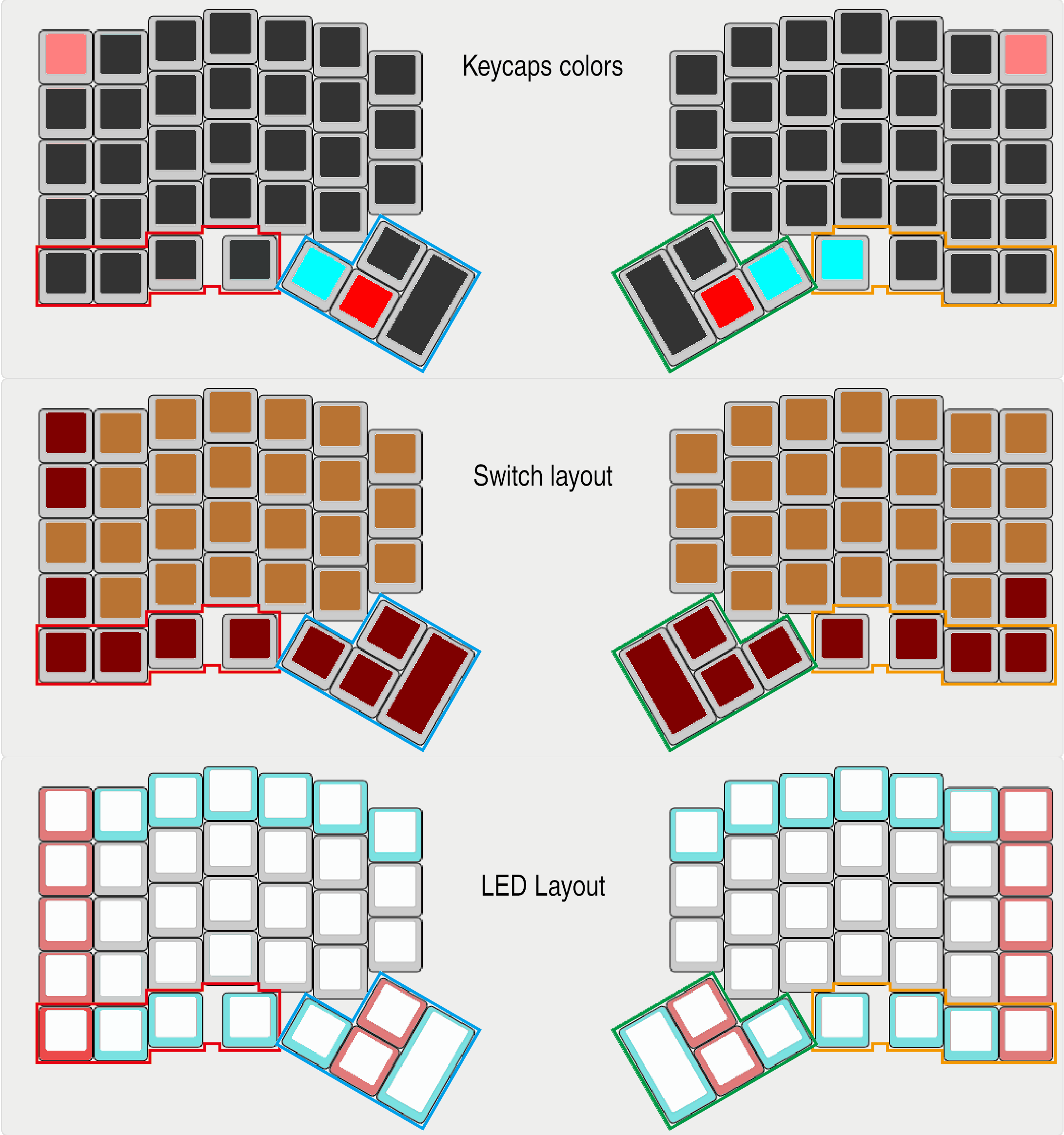
The same process also went into selecting the keycaps and the amount of LED to order for the build. All this was also done while thinking of the optimal way to order the various components to strike a good trade-off between the actual cost of the keyboard, the quality of its components, the delivery cost and the time needed for delivery of said parts.
Building order and notes
DISCLAIMER This should not be considered as a build guide, but just an additional reference with some potential problems that do not necessarily appear at the conceptual level when planning the keyboard build. It is more of an attempt to document what worked well for me, as well as the mistakes made along the way.
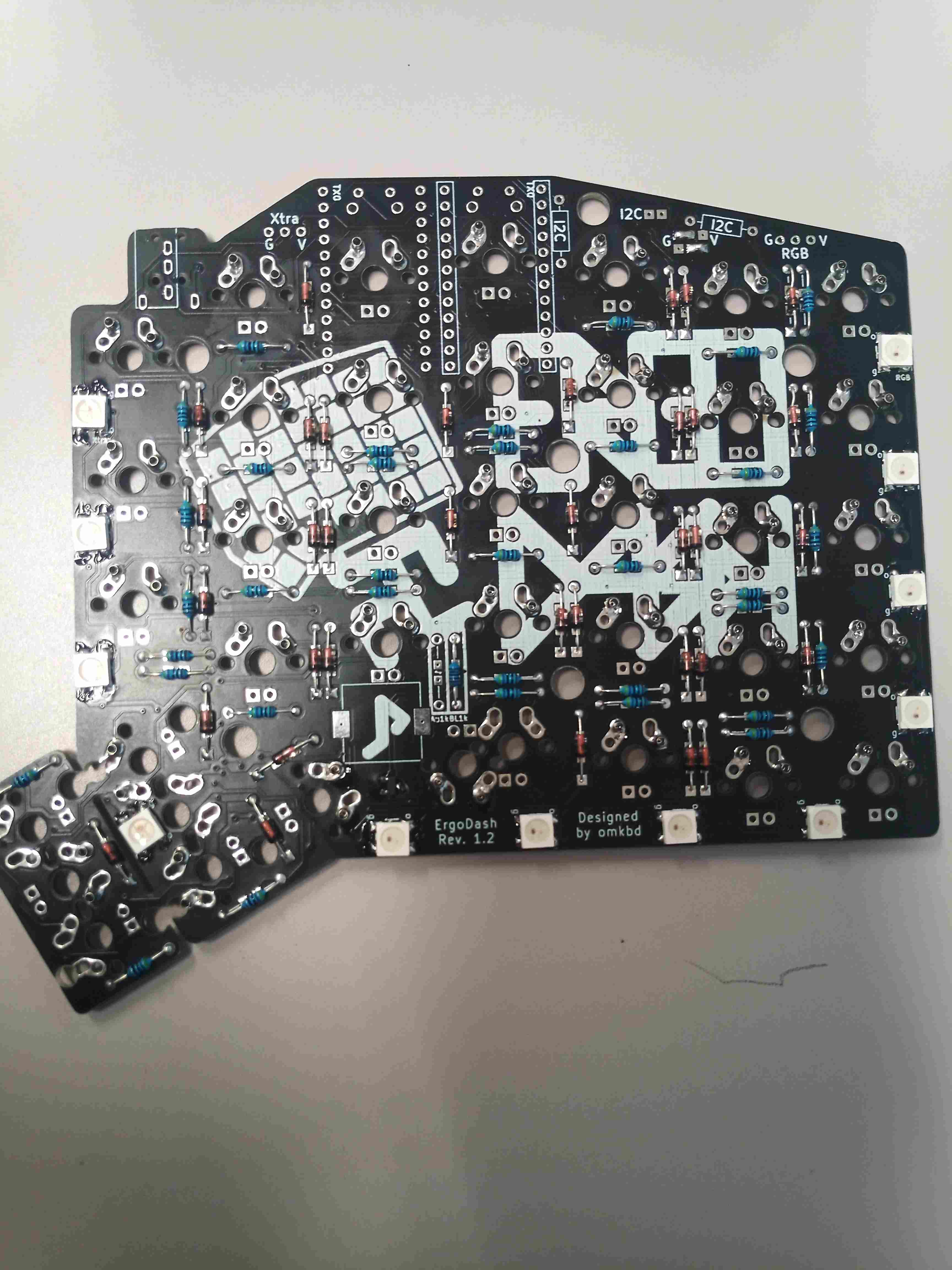
1. Diodes and resistors
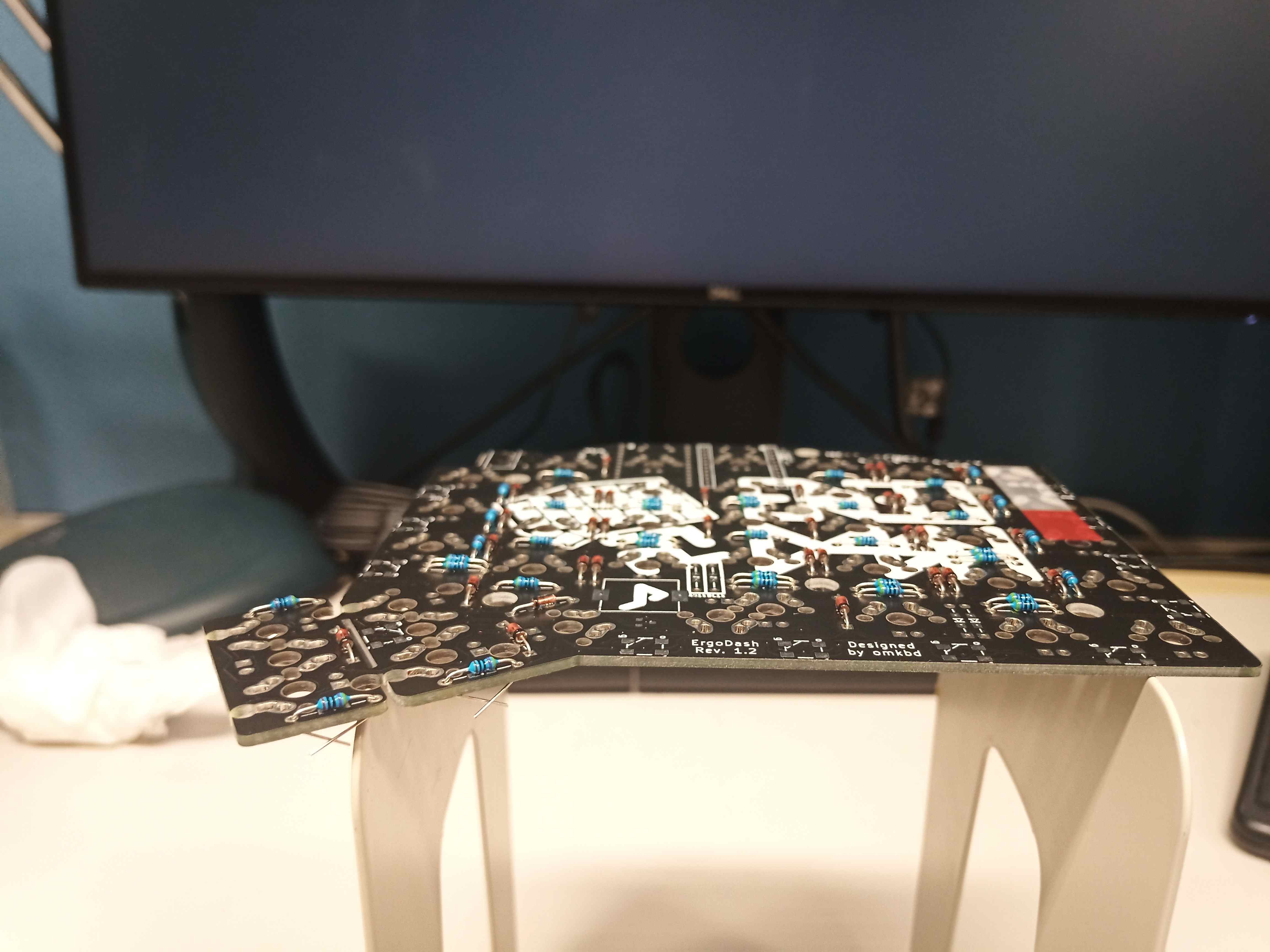
Mounting the diodes, 1K, and 470 Ohm resistors ( if using backlight) is pretty straightforward. Using some kind of sign to not mess up the underside and upper board for each of the left and right boards is recommended. Otherwise, one might end up with two left or two right-hand boards if not careful enough.
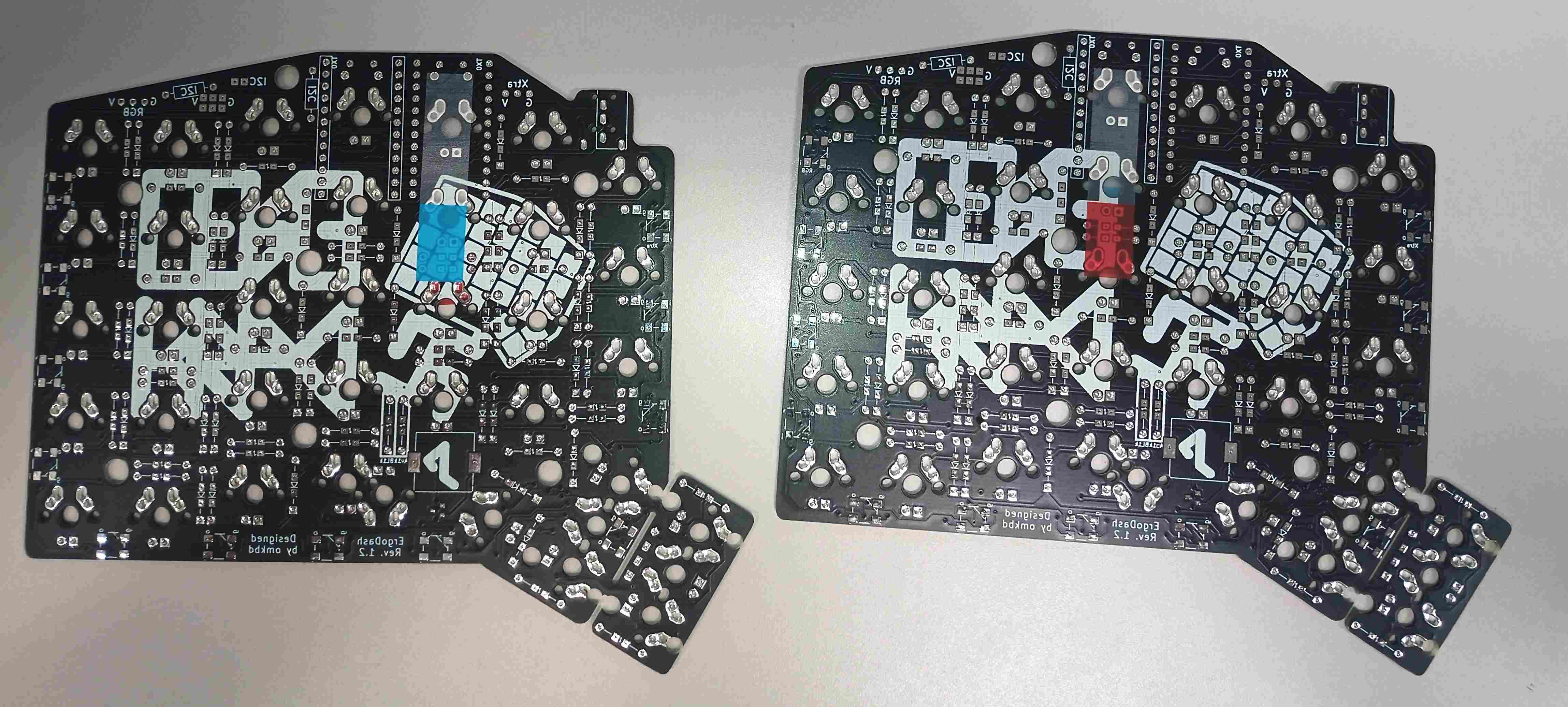
For the diodes, as per the official guide, it is important to align the black stripe leg with the square holes, and the other leg in the round one. The resistors, on the other hand, can be mounted without a specific orientation, into the slots with both round holes.
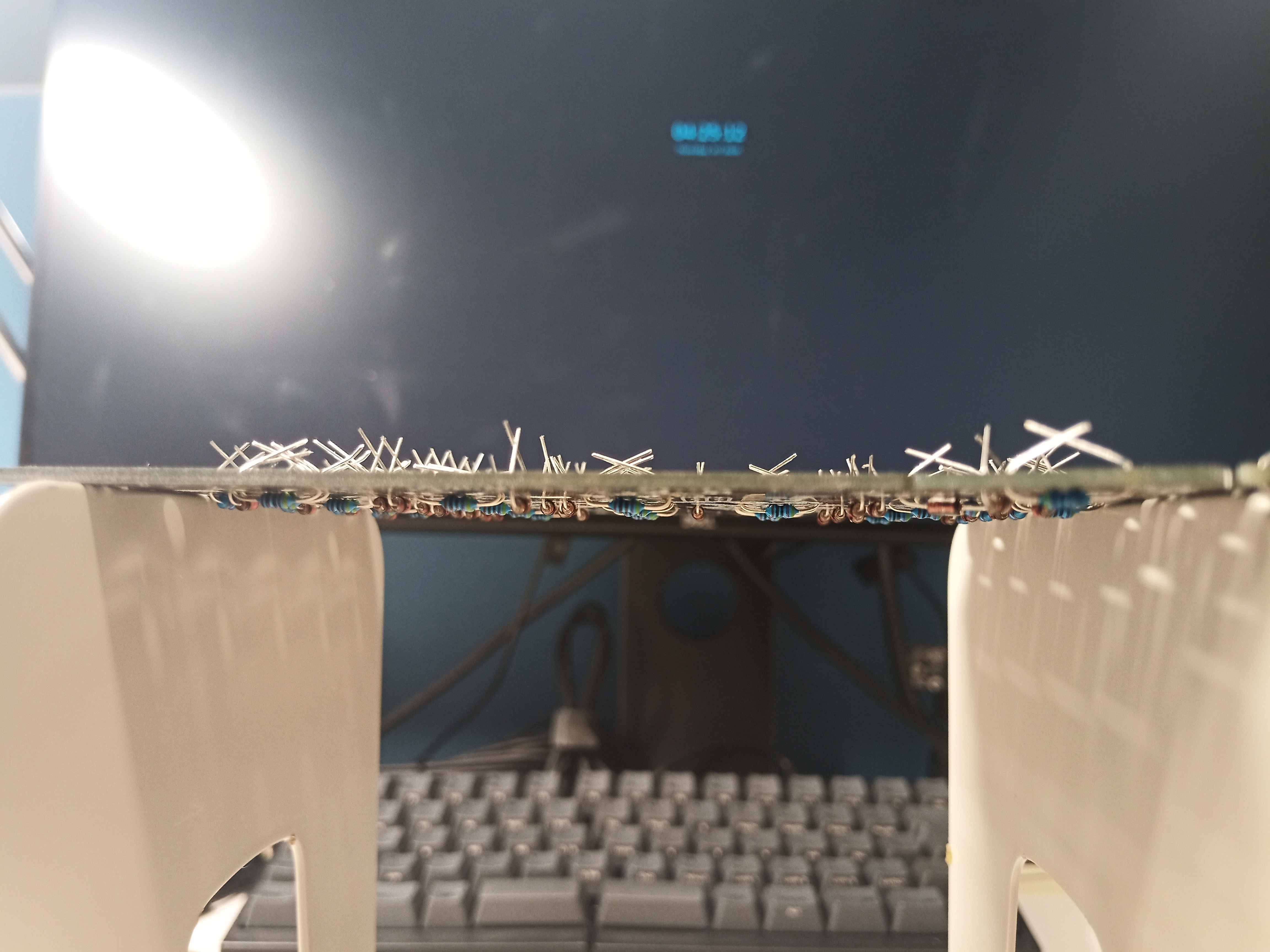
For efficiency, I found it useful to first insert all the diodes or resistors while bending and pre-trimming their legs on the other side, then flipping the border and soldering them in one pass.
Double-checking, and even triple-checking the orientation of the diodes especially is advised before going to the soldering phase. Final trimming after everything is soldered.
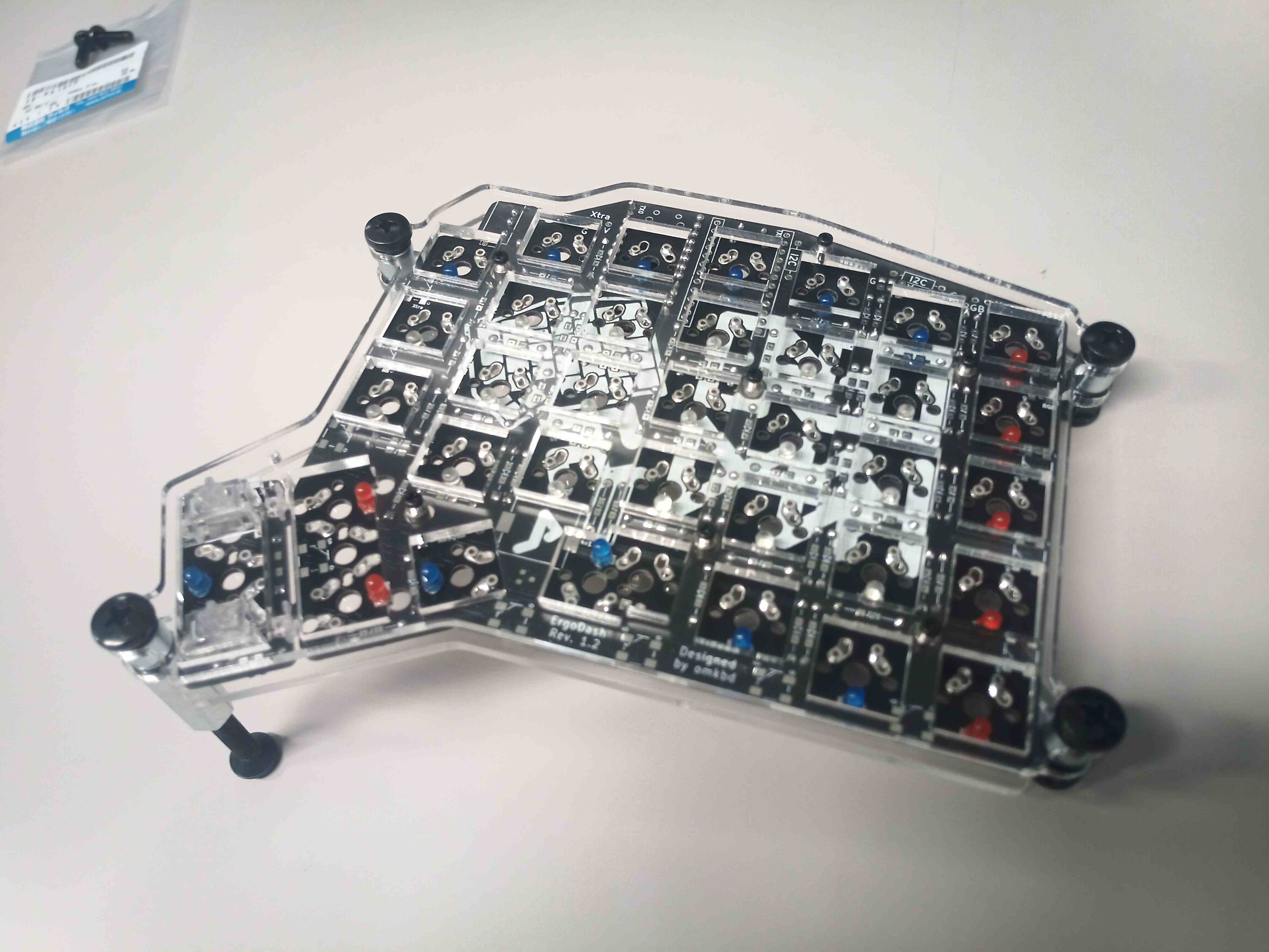
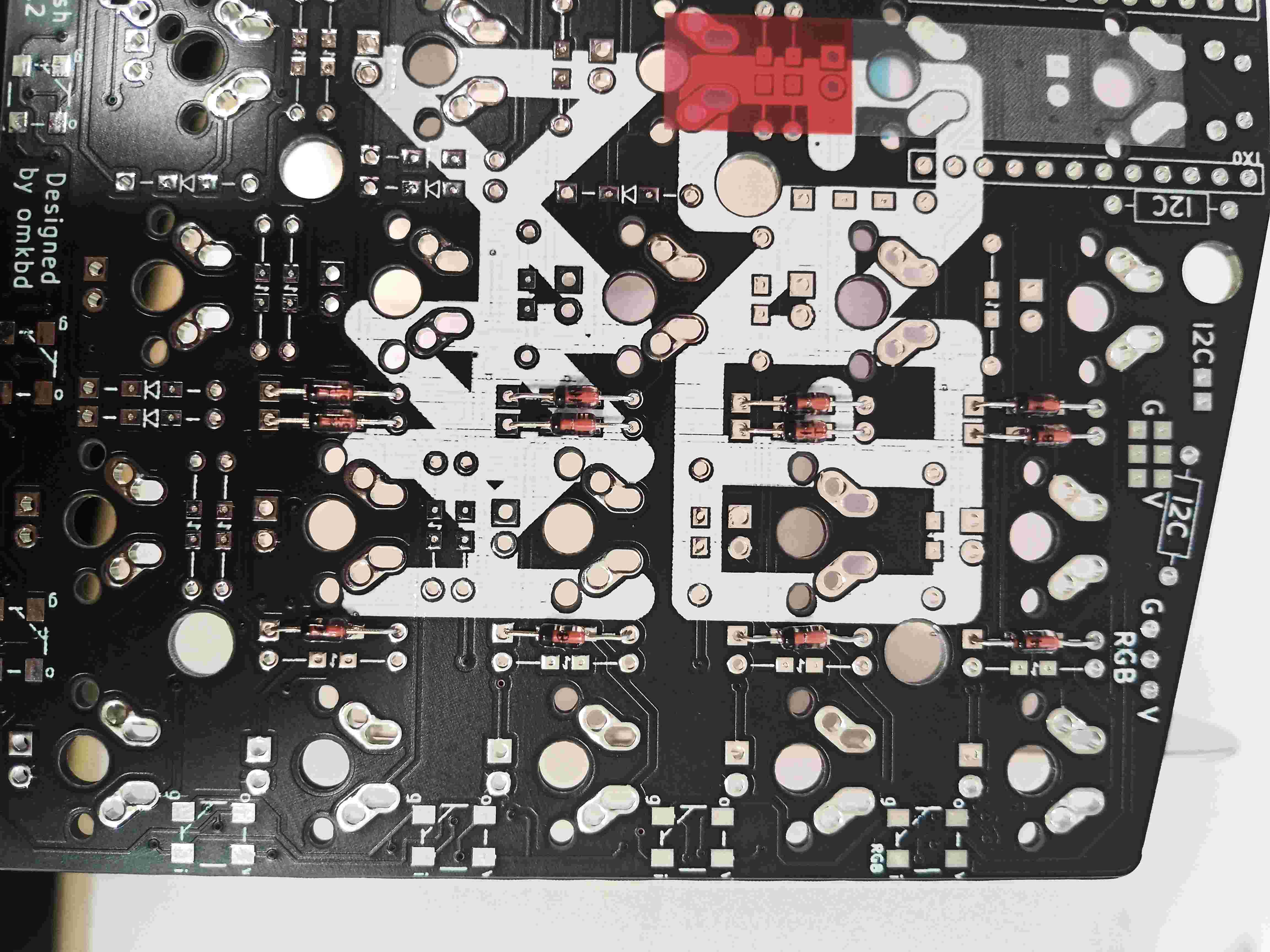
2. Mill-Max 0305 receptacles (Switch hot-swap, optional)
Experimented with a few methods, namely:
- Mounting the diodes and the resistors first, then the receptacles. Unfortunately, doing it in this order made it hard to solder the receptacles since the already installed diodes and resistors elevated the board from the soldering board, making it hard to get the receptacles to sit flat in the holes. (Did this on the left board at first)
- Installing the receptacles first (right board) then the diodes and resistor later, to mitigate the problem that occurred when mounting the left board as expended above. Despite the board being flattened down on the working mat, it was still hard to get the alignment of the receptacles right.
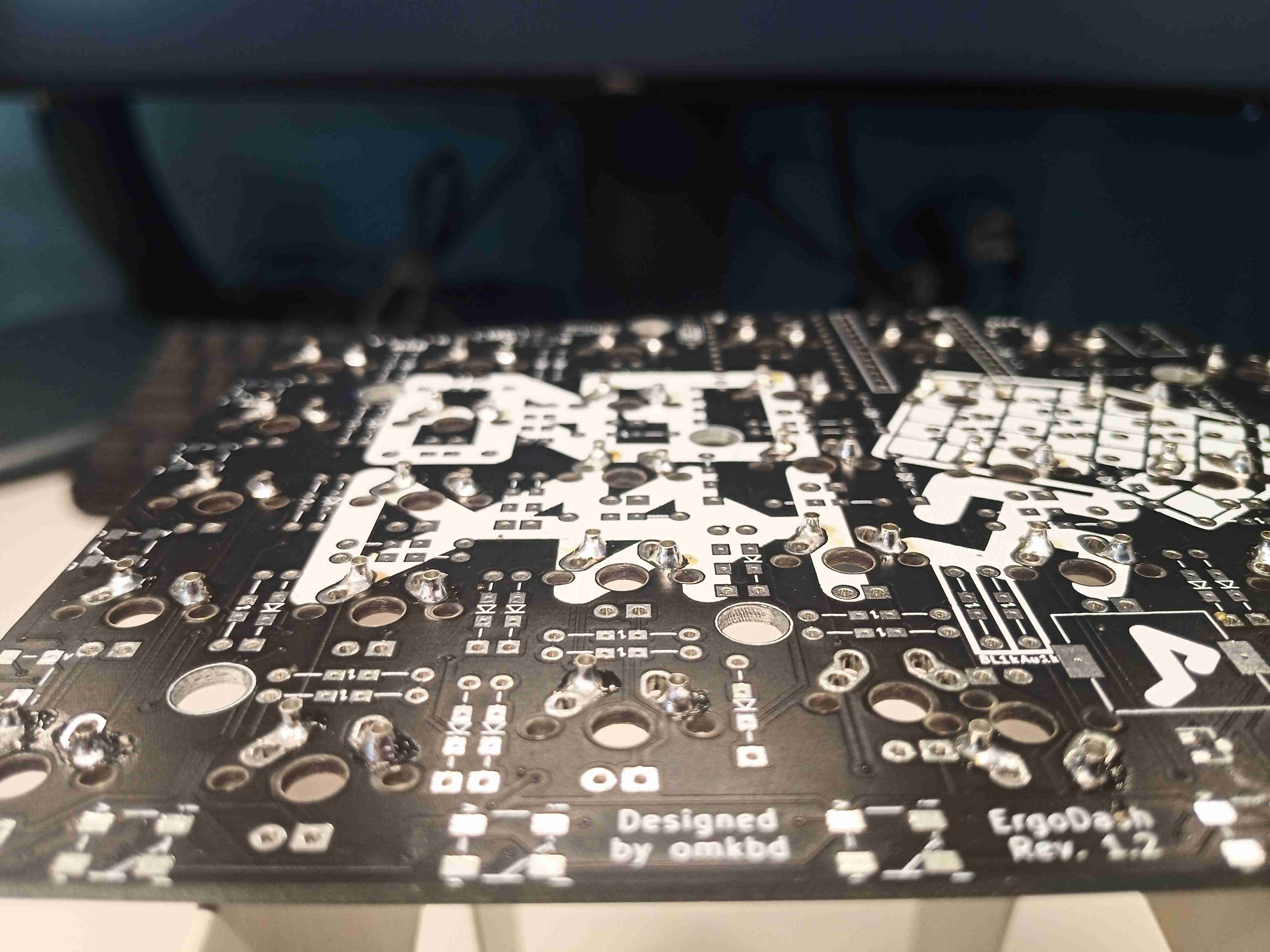
The final strategy to set up the Mill-Max receptacle efficient and with optimal accuracy, with either diodes and resistors already mounted or not, was to first set all the receptacles for one board, then insert the switches as it is. Then, using a cardboard to press on the switches on top, flip the board to get access under the board where we solder the receptacles. When soldering the receptacle, press down the board until the switches are all the way done. This makes sure that not only the receptacles are well aligned with the switch legs, but that they sit nicely and as closely as possible to the board. Once done, remove and store away the switches to continue mounting the other components.
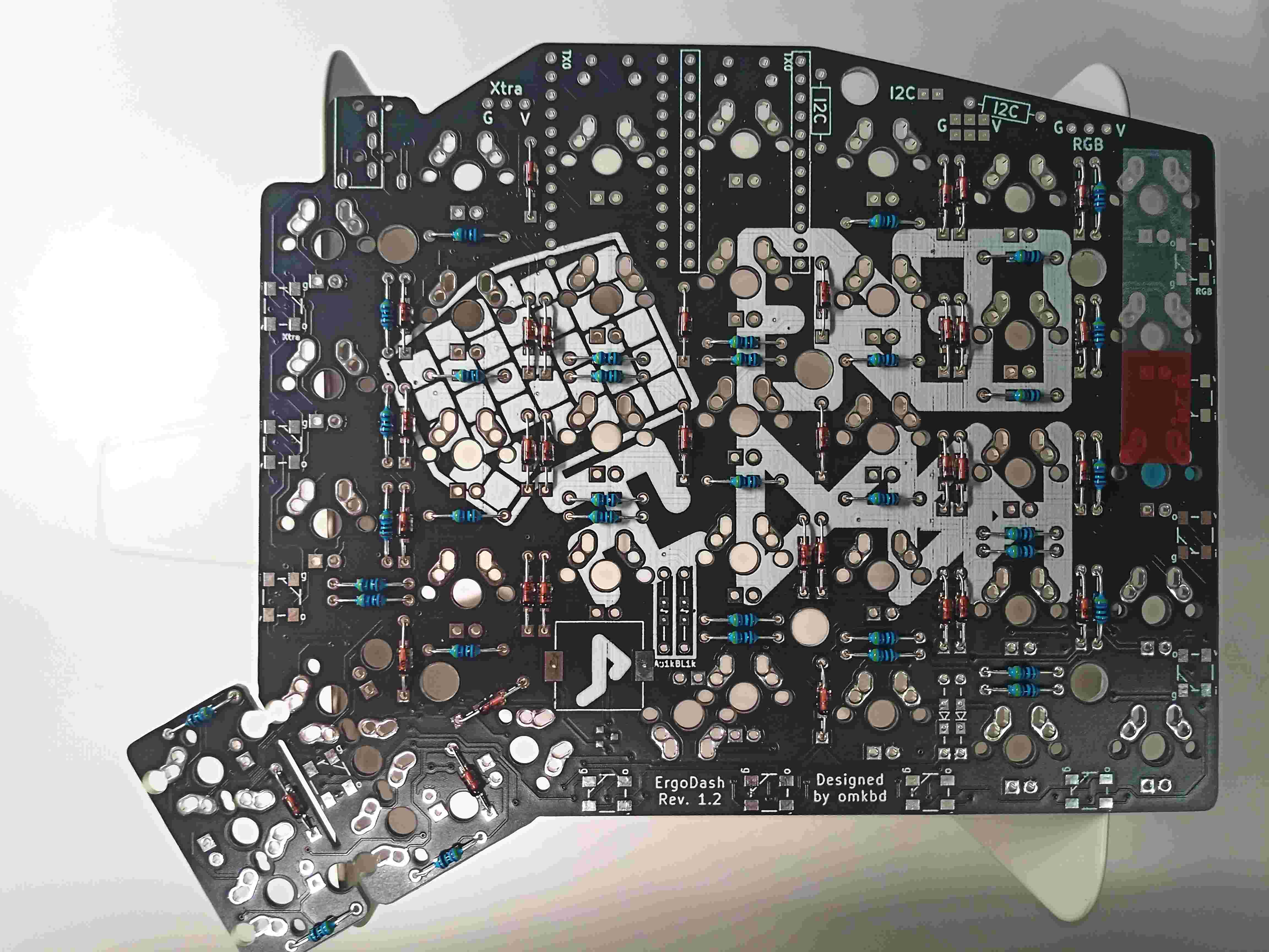
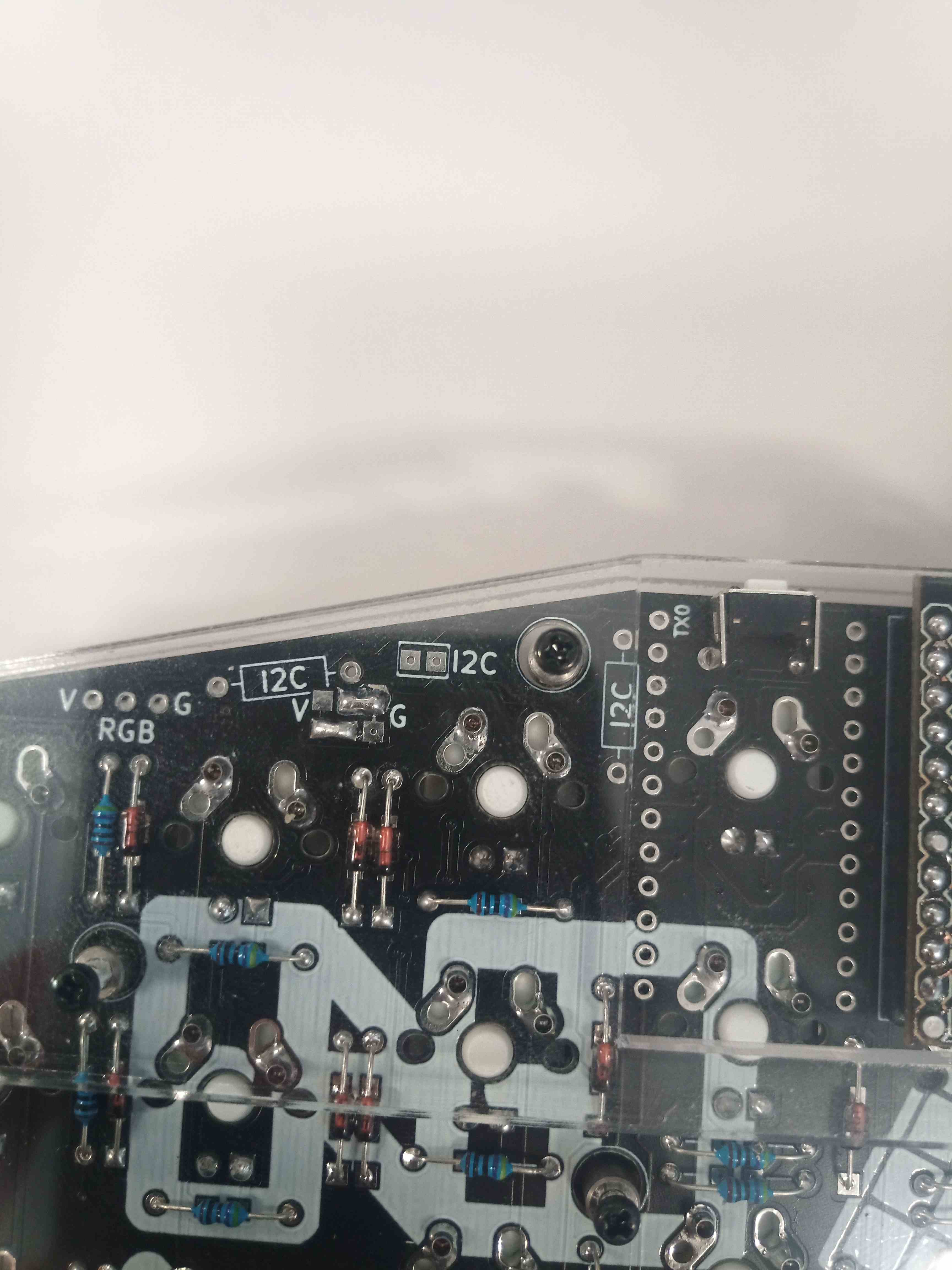
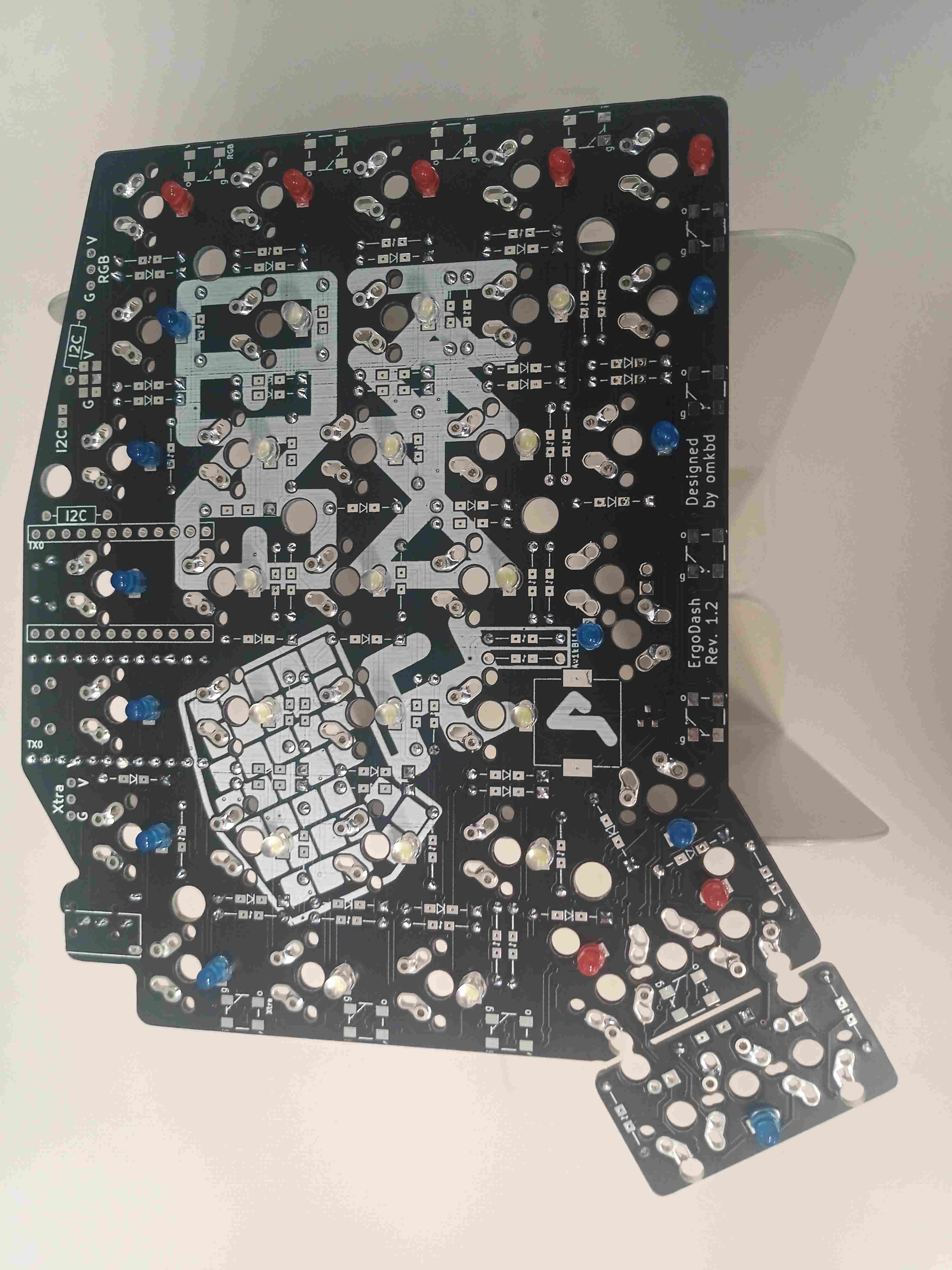
The final result on the right board which got the receptacles installed first is as follows. The left board already had diodes installed before the receptacles were soldered on with the help of the switches as a support, but the results were the same anyway.
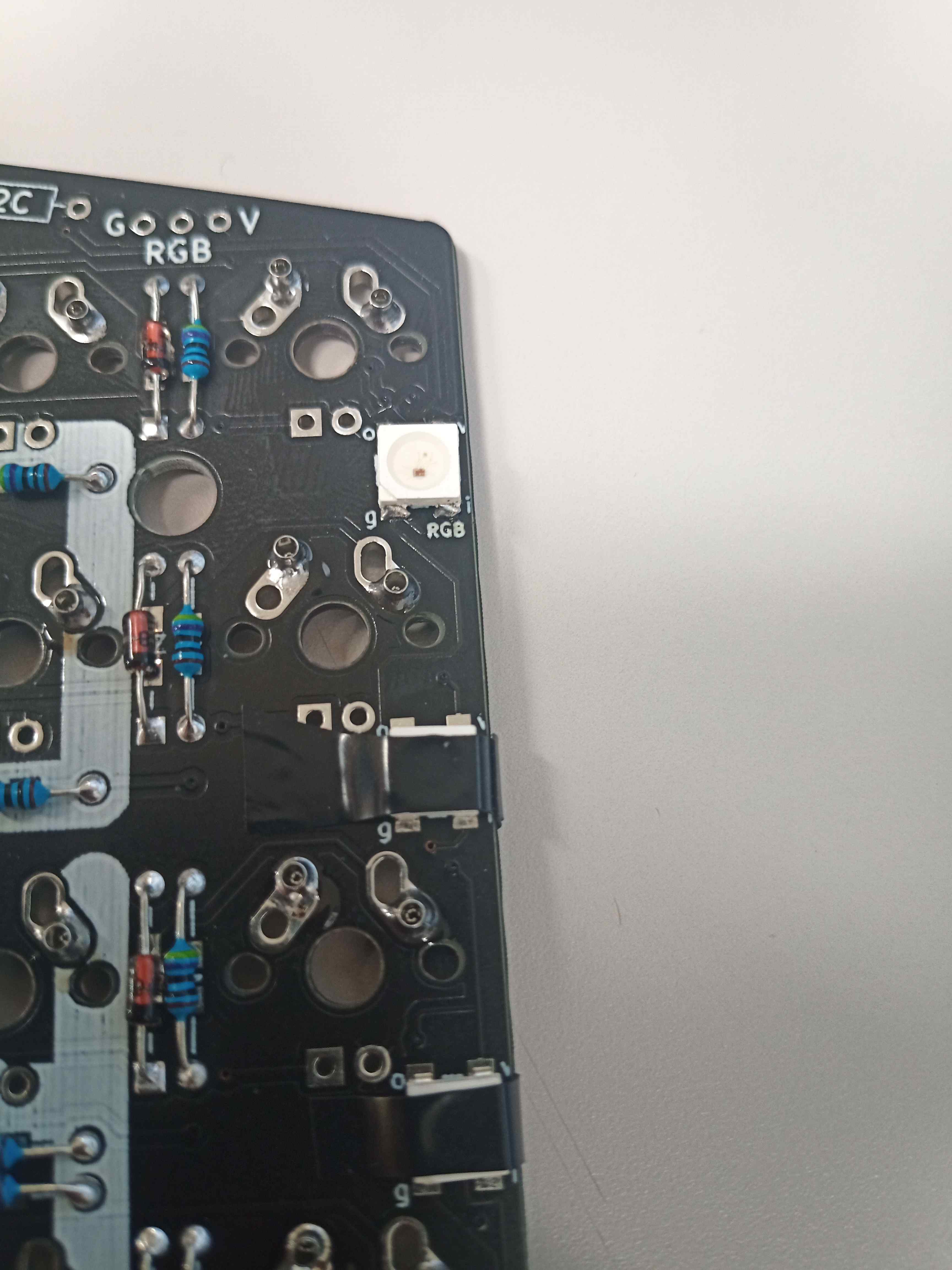
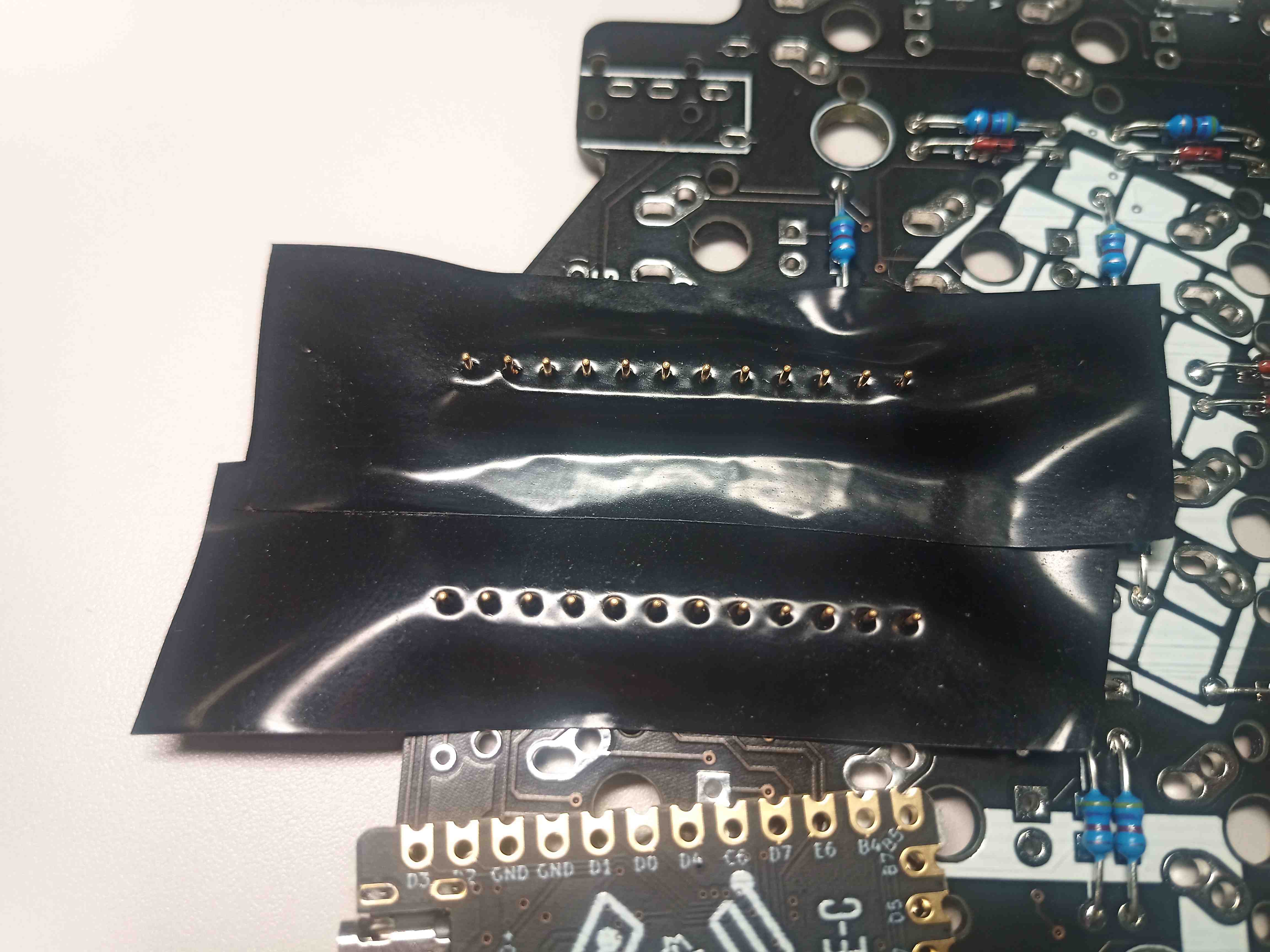
3. RGB Underglow Leds (Optional)
The RBG LEDs are quite light, and their pad is quite small, soldering them can be quite challenging. Inspired by the original building guide, it was quite useful and efficient to set all the LED down with some tape so they hold onto the board well enough, with the pad properly aligned. To be able to do all the soldering in one go, cutting a slim piece of tape so that all the 4 pads are exposed was quite useful. Regarding the soldering itself, with a standard soldering tip, first putting the tin on the pad and the board, then quickly touching it with the soldering iron was enough. This was even better than I expected as I had a bad experience soldering really small components back when I used a really old and thick tip iron.
4. Mosfet for Undeglow / Backlight (Optional)
Similar to the underglow LED, pre-installing the Mosfet with some tape to hold it down was useful. Given its small size, however, first set the tape to cover the side with only one pin. This way, soldering the two pads on the other side is more stable. Then remove the tape, and solder the remaining pad. The soldering procedure with standard iron tip size is the same as with the underglow LED: the first approach the tin to the pad and the board, then a quick touch with the iron tip and it holds it down. See the latest picture above.
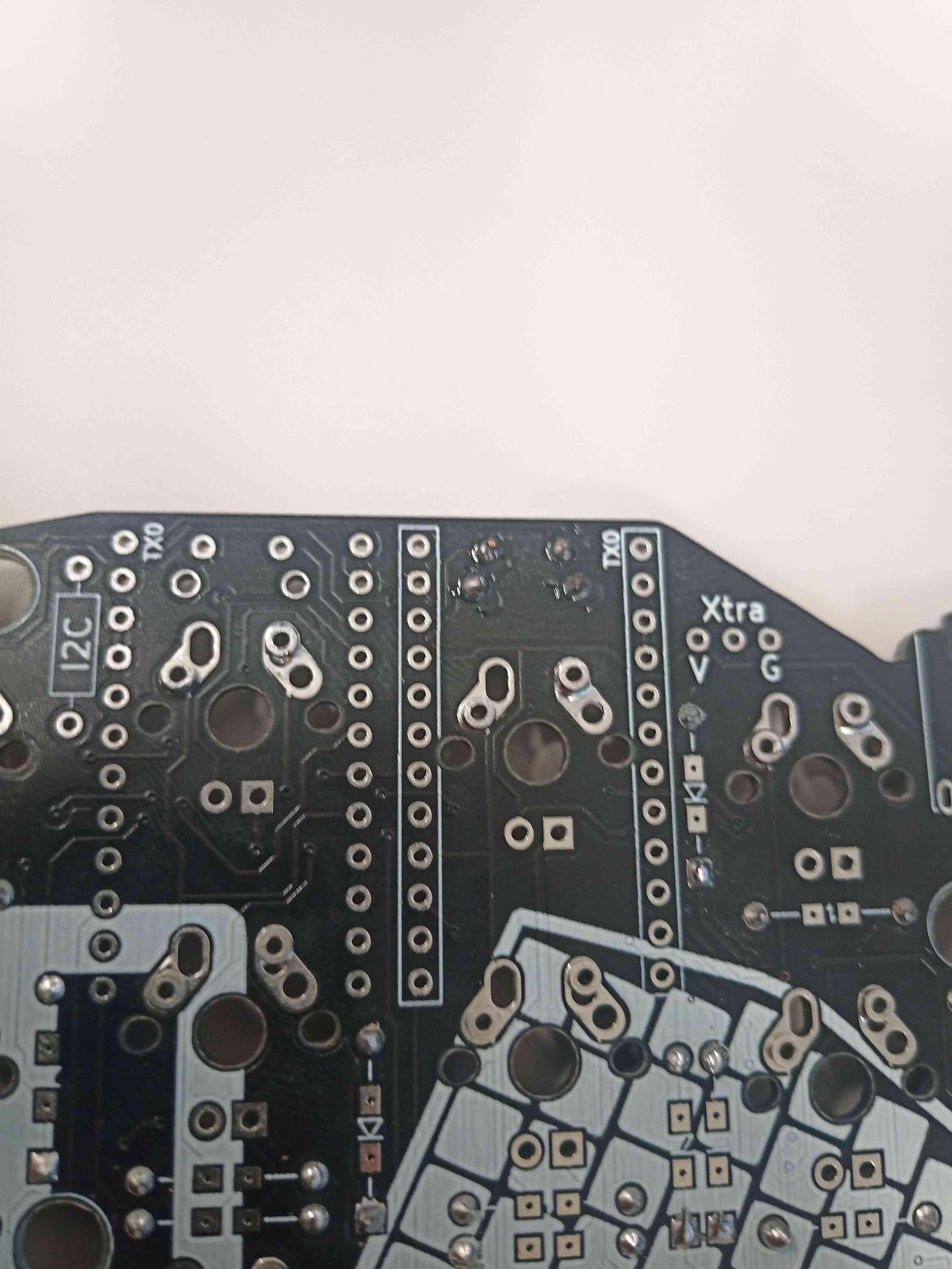
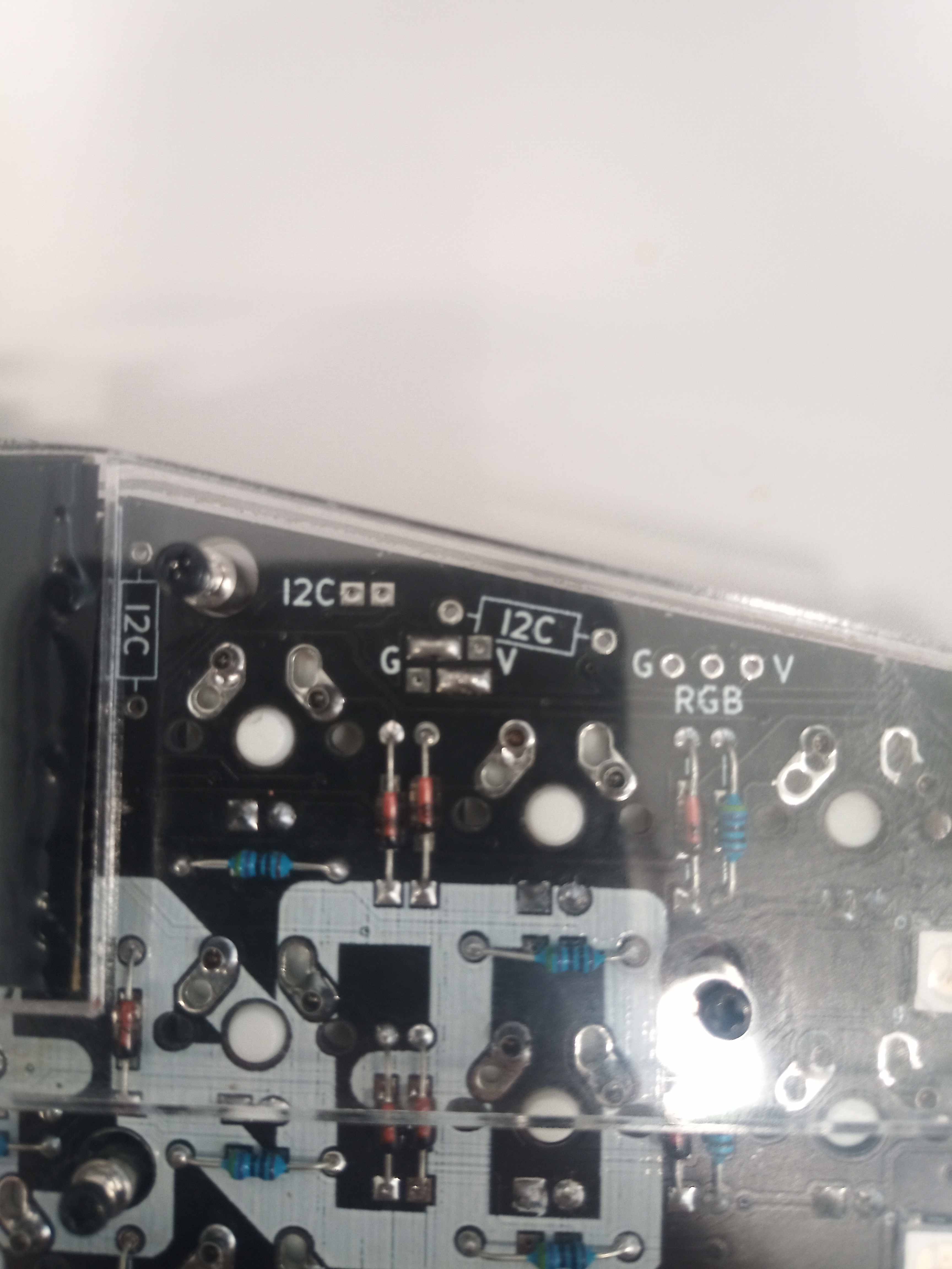
5. Shorting the jumpers to designated left and right-hand board
This part can be a little bit confusing given that the way connect the pad depends on which version of the board is owned (rev 1.1 or 1.1). After a bit of trial and error, what happened to work was to just follow the top instruction of the guide, namely to form that “z”-shaped Tetris block and have them facing each other when the boards are flipped upside down. (Board Revision 1.2)
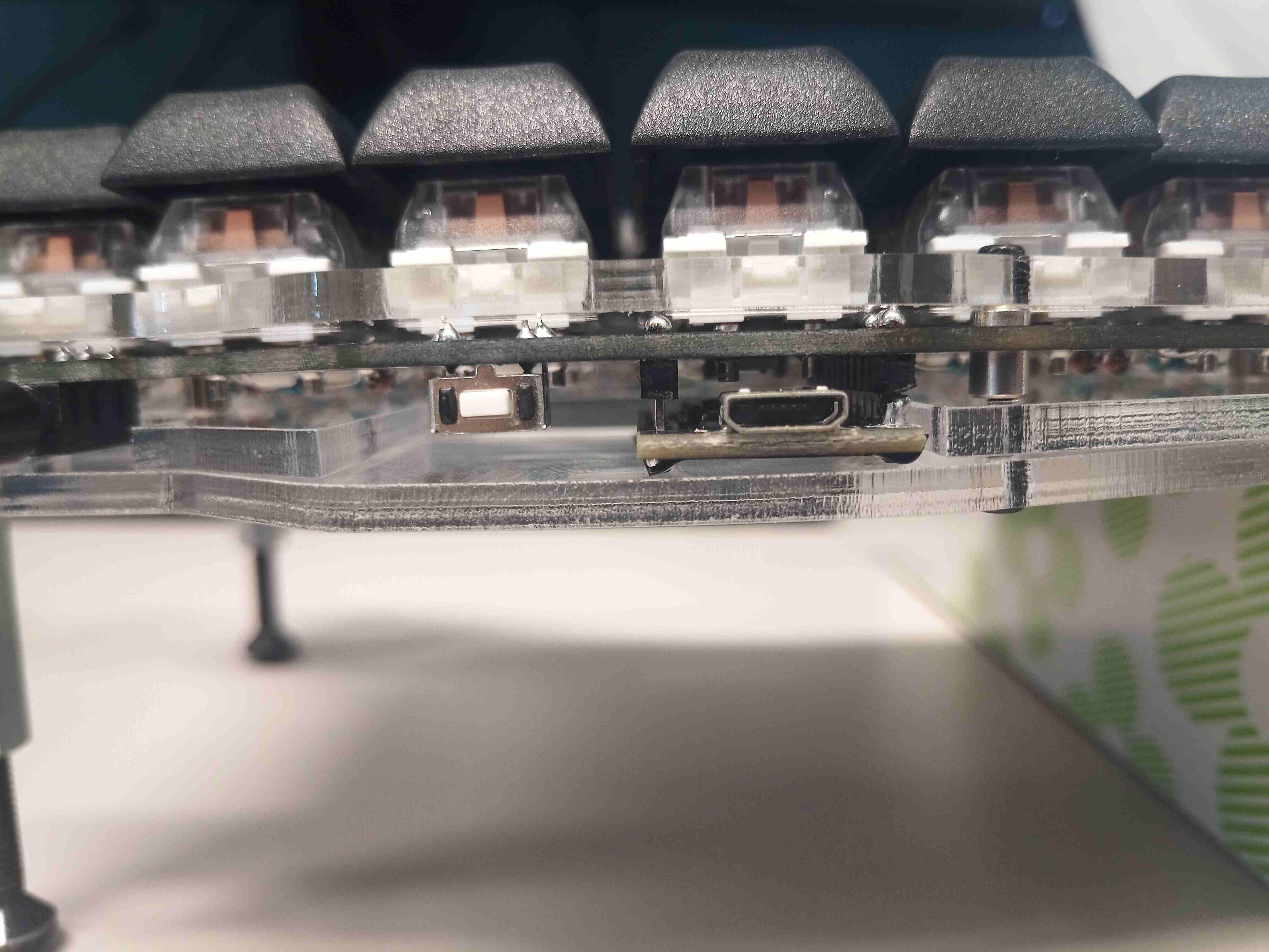
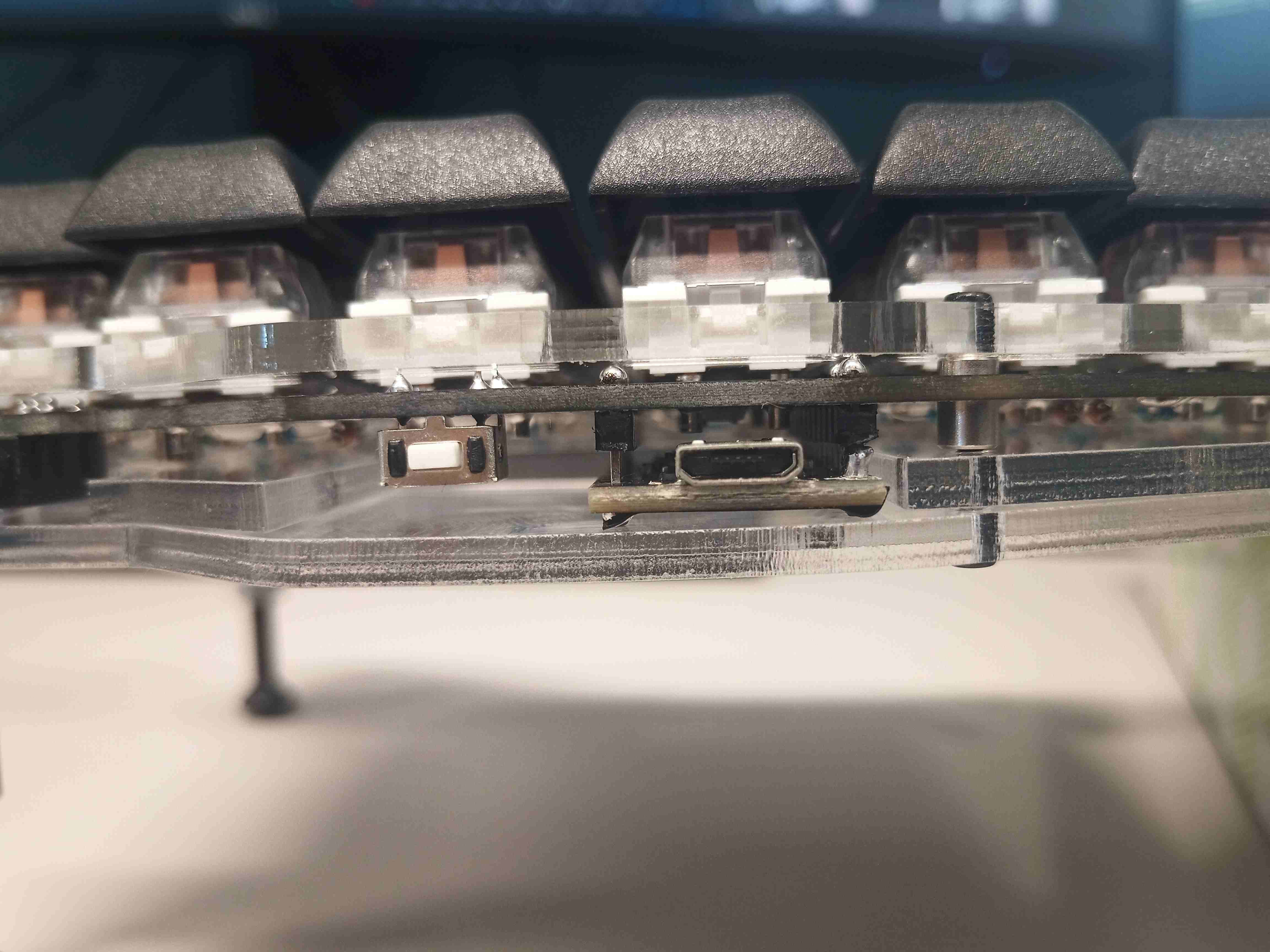
6. TRRS Jack and Reset switch
Probably one of the easiest parts. Both are to be inserted on the underside of the board, then soldered on the upper side. No particular comments.
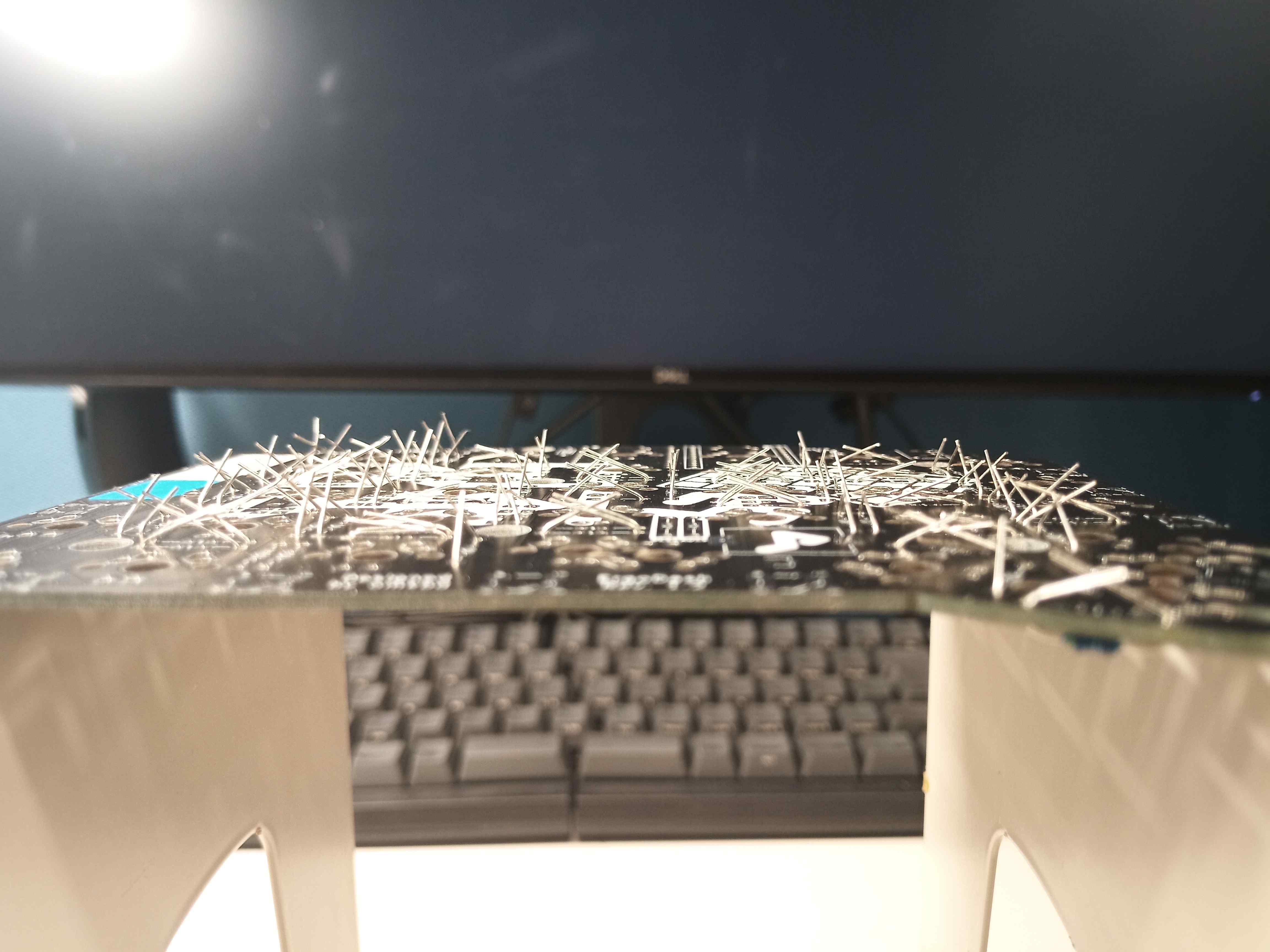
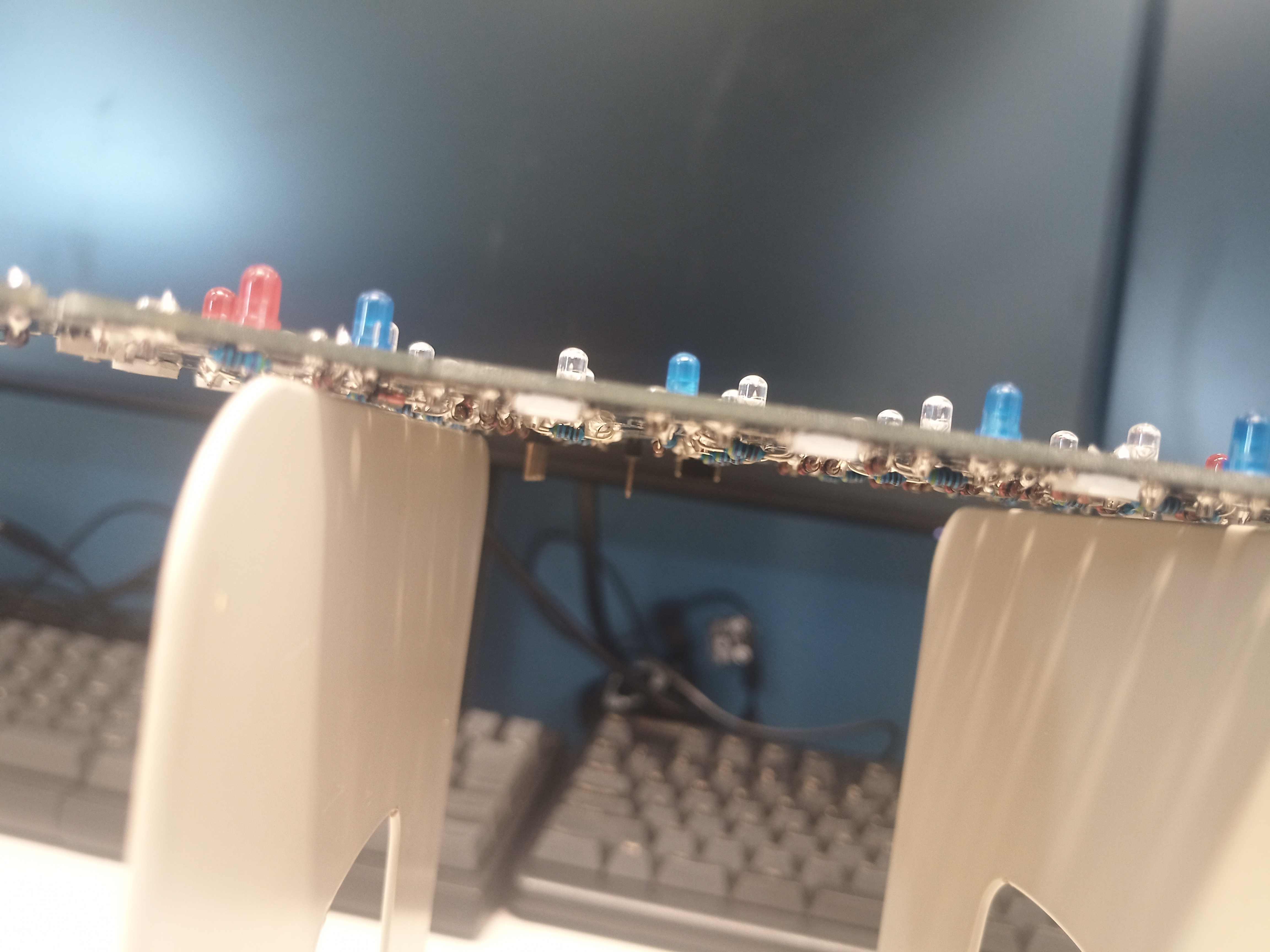
7. Backlight 3mm LED (Optional)
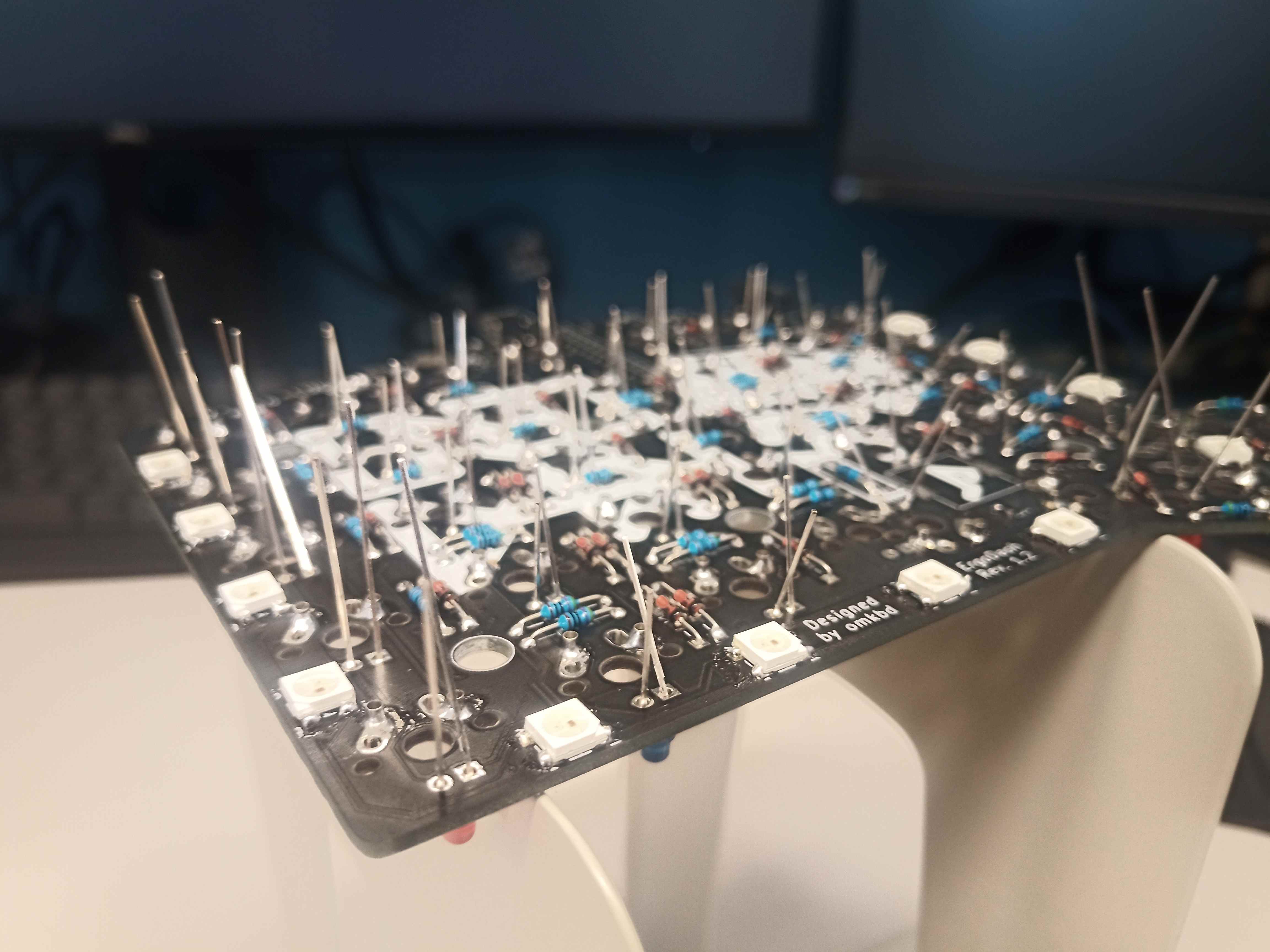
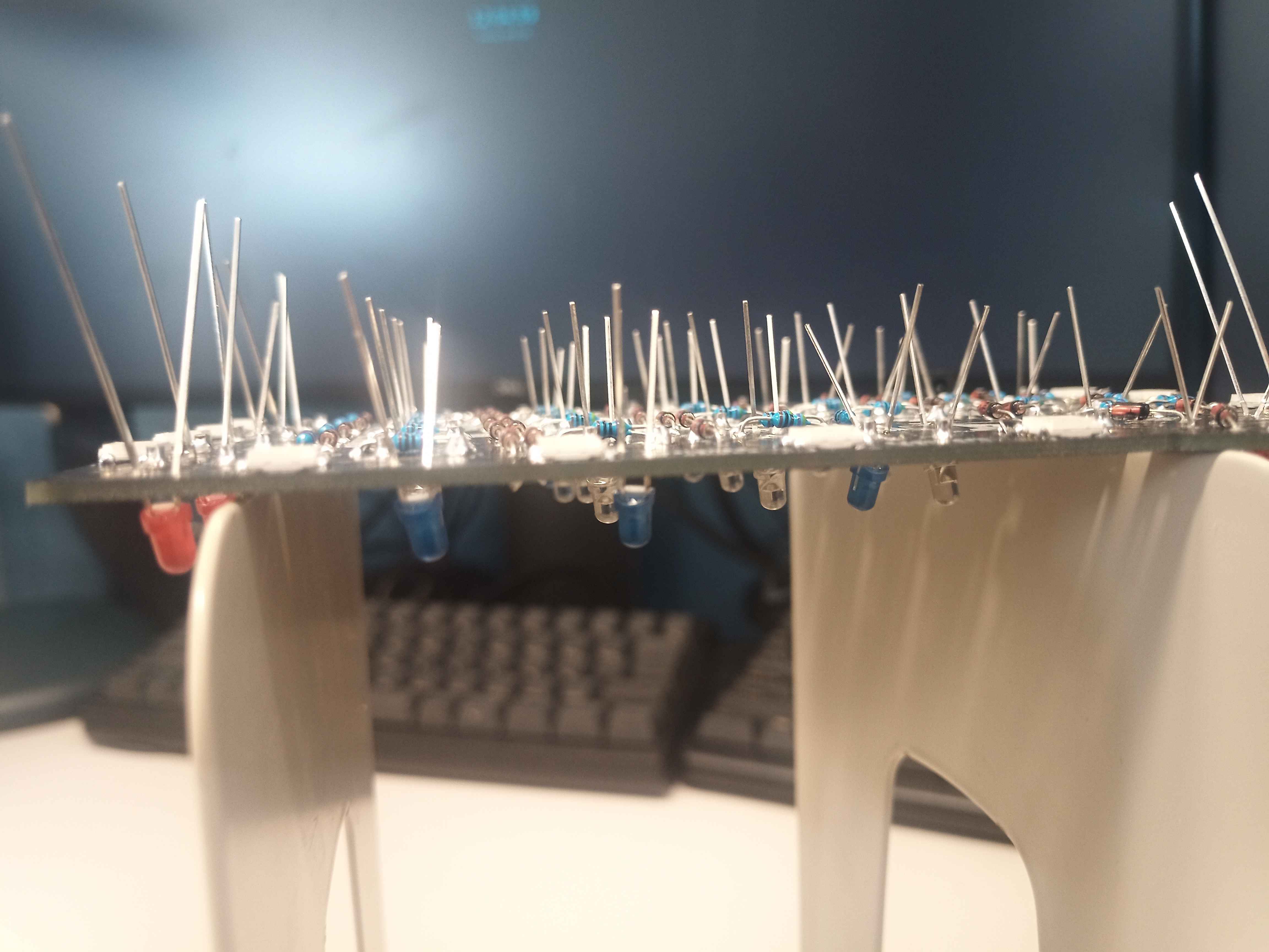
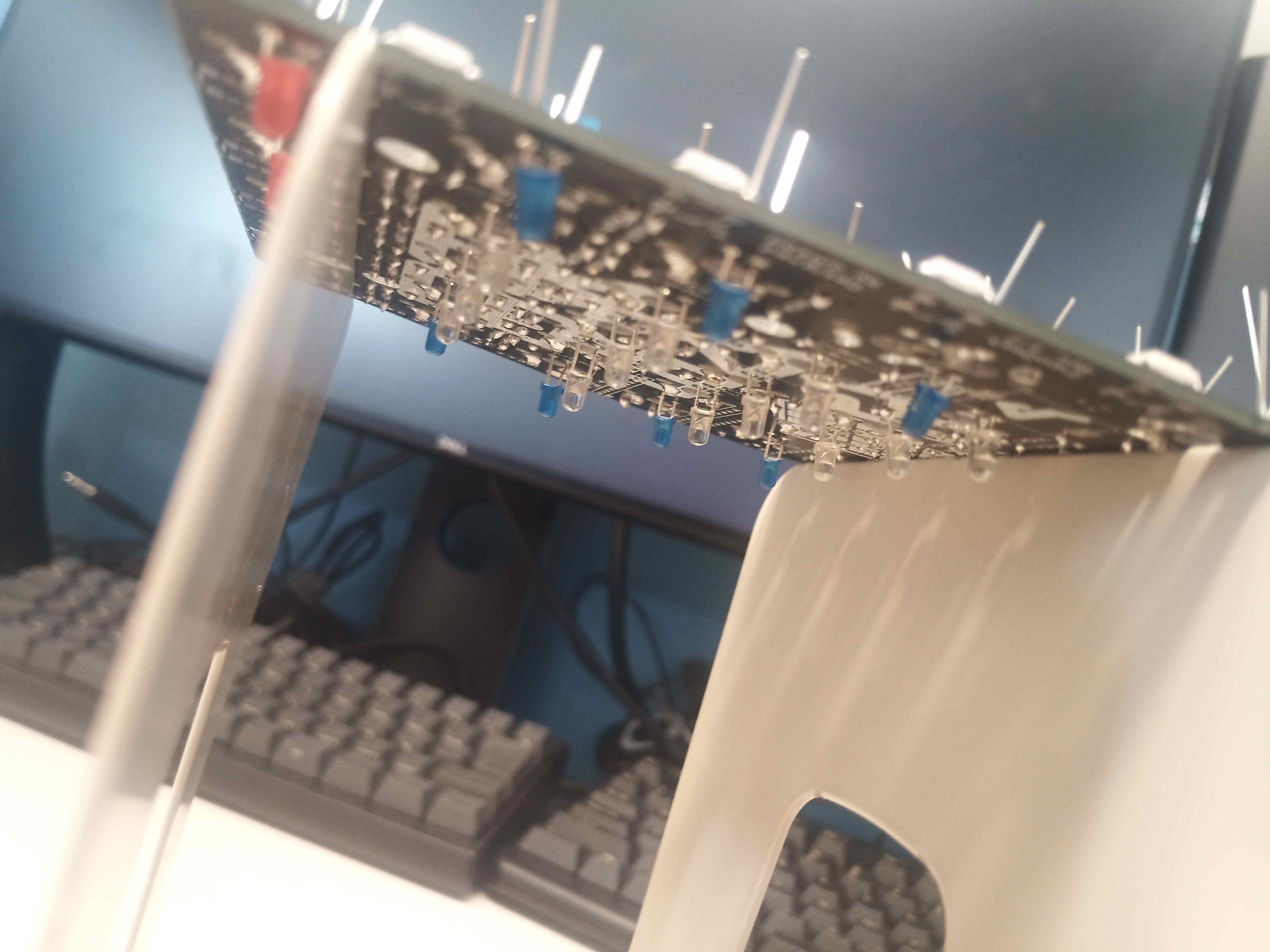
Similar to the diodes, first inserted them all and bent only one leg so they do not fall off when the board is flipped for soldering. Then, after flipping the board, pull the LED by the leg until it sits flat on the other side of the board, then soldered both legs, while pressing the LED from the other side with a finger. Once all the LEDs were submitted to such a process, trim the legs for the final result.
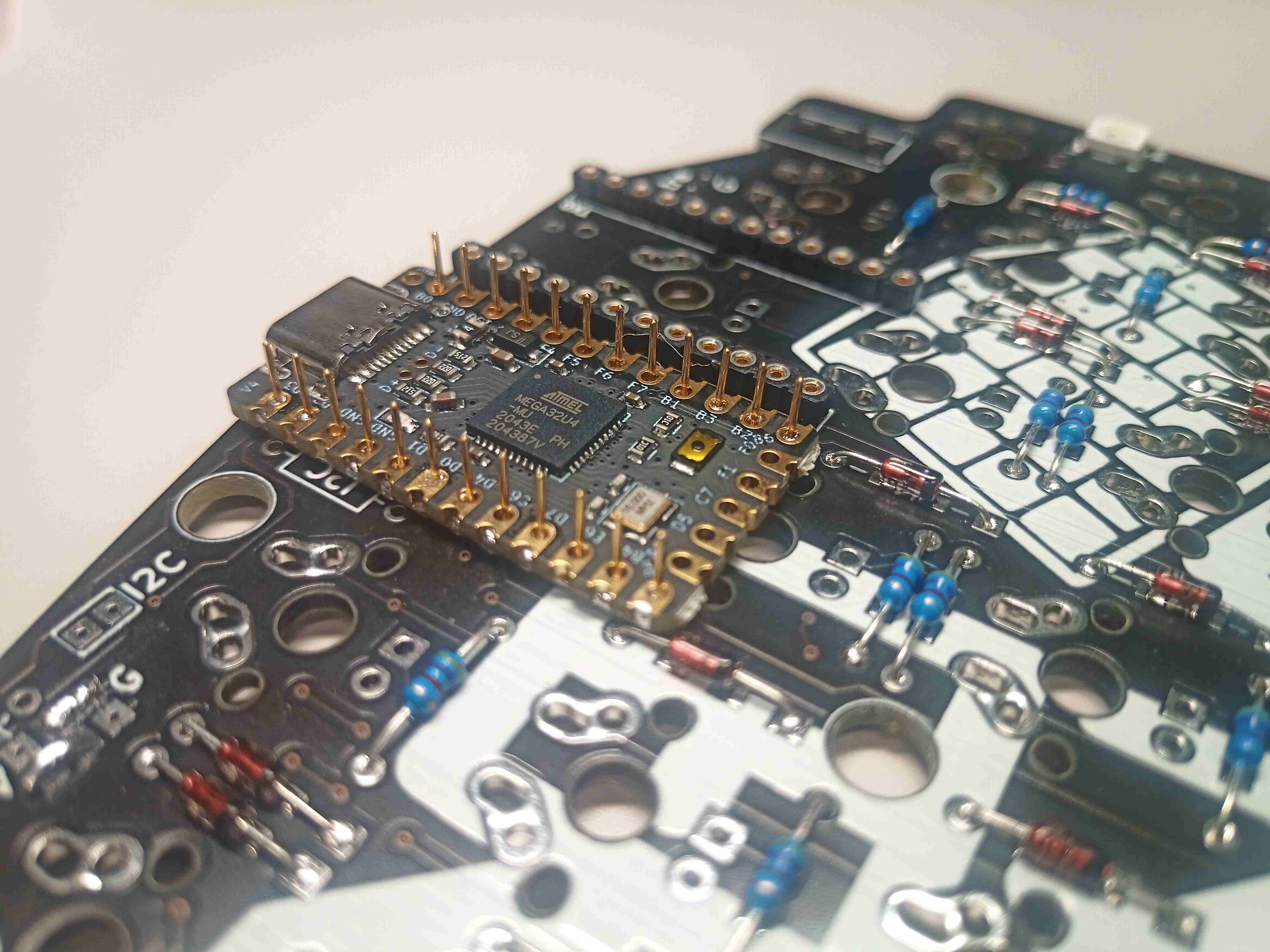
8.a Pro Micro and its headers
Warning Soldering the Pro Micro on is a no-going back operation, as desoldering it down is quite difficult (speaking from experience). The danger here is that for each board, two switches, as well as their corresponding LED, have to be soldered in a location the Pro Micro covers afterward. It is therefore important to make sure that especially those key switches are soldered (in case no hot-swapping is used), and their LEDs are also installed BEFORE soldering on the Pro Micro. Furthermore, soldering the switches requires installing the upper side of the case. Therefore, the build order when not using hot-swappable switches is drastically different.
First installing and soldering the headers of the pro micro on the underside of each board. Then, after sliding the Pro Micro at the appropriate height on the header pins, we solder again.
To avoid the switch receptacle touching the Pro Micros, I first made the mistake of setting the latter too high. By the time I realized the mistake however, it was already too late, as the Pro Micro were virtually impossible to desolder: an overly elevated Pro Micro results in being unable to properly flatten the last, smallest part of the sandwich case that is supposed to cover the Pro Micro itself. In this case, it was still possible of closing the case completely, but at the price of that last small part bowing slightly, depending on the elevation of the Pro Micro …
In retrospect, probably not that big of a deal, but it kept me awake for a few nights.
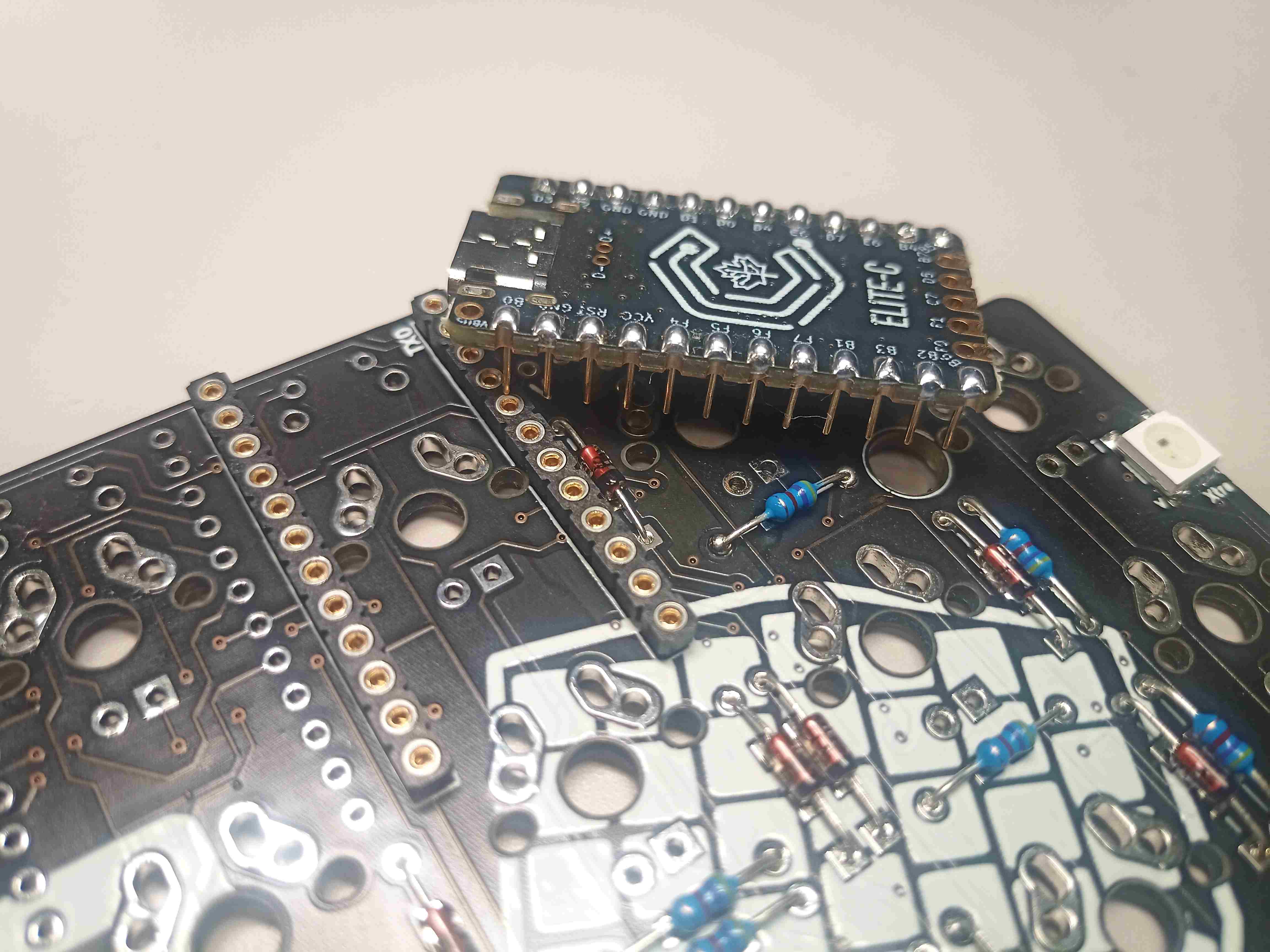
8.b Socketed Elite-C (2022-05 Update)
This is a slightly altered build that uses an Elite C microcontroller(MCU) for each side. The MCU is socketed to the board, instead of being directly soldered like in 8. a to make repairs or upgrades easier.
A great introduction to socketing can be found here, while the required parts are specified in the exhaustive list above.
After installing the header sockets into the board, they need to be taped. Otherwise, when soldering the socket pins to the MCU, the solder tin is likely to drip down into the socket holes and solidify, completely defeating the purpose of socketing in the first place. (Yet another lesson I had to pay an Elite C and the header socket to learn…). Then, the pins can be inserted into the sockets by poking into the holes. Then, the Elite-C can be fit on the pins, while making sure to align the pins to their corresponding holes (usually written in silk lines on the board and the MCU).
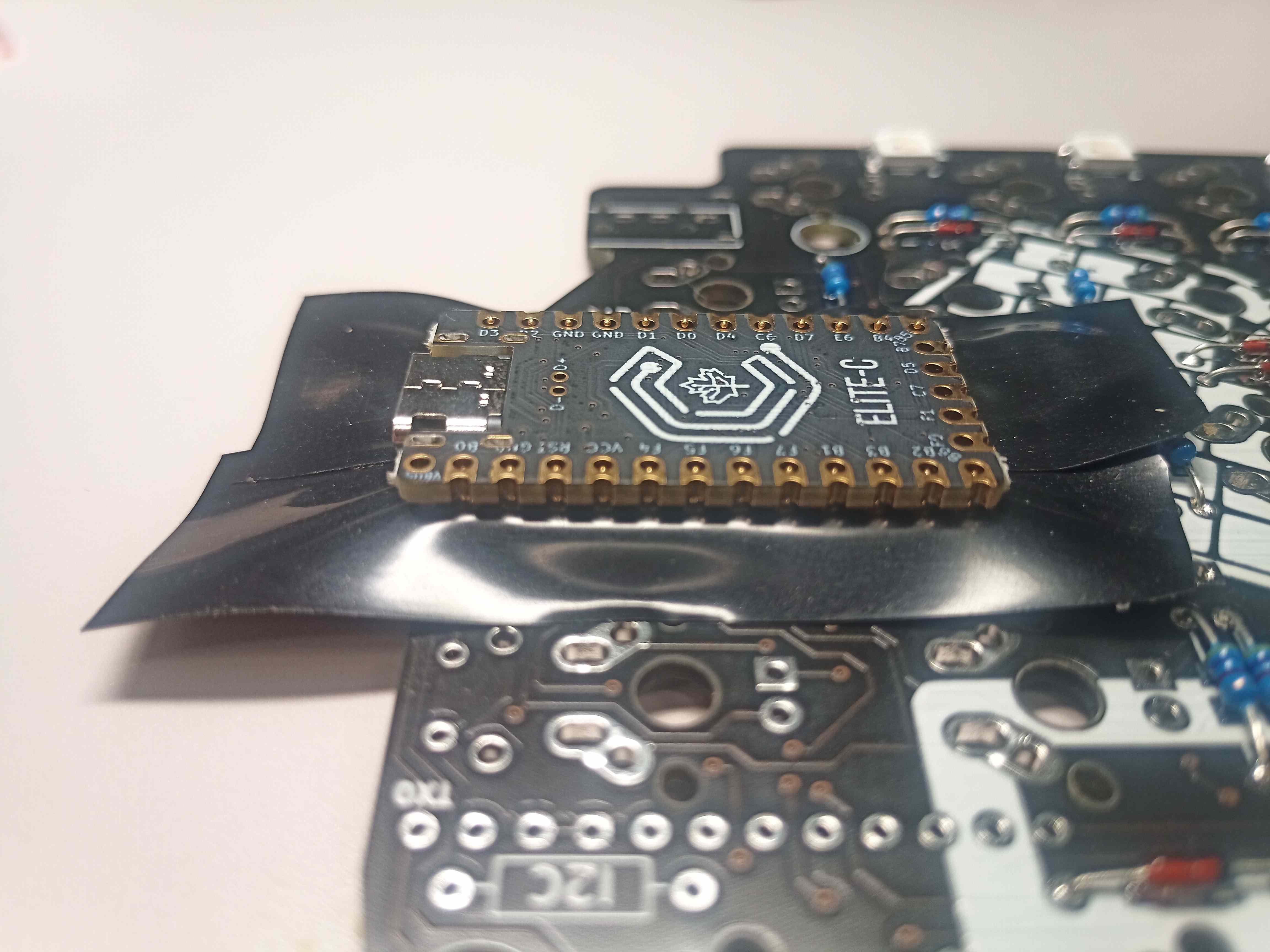
After making sure the Elite-C is flushed with the headers and that there is no gap, solder all the pins. Then Elite-C can then be removed, as well as the tape, before being inserted back again, maybe for the last time.
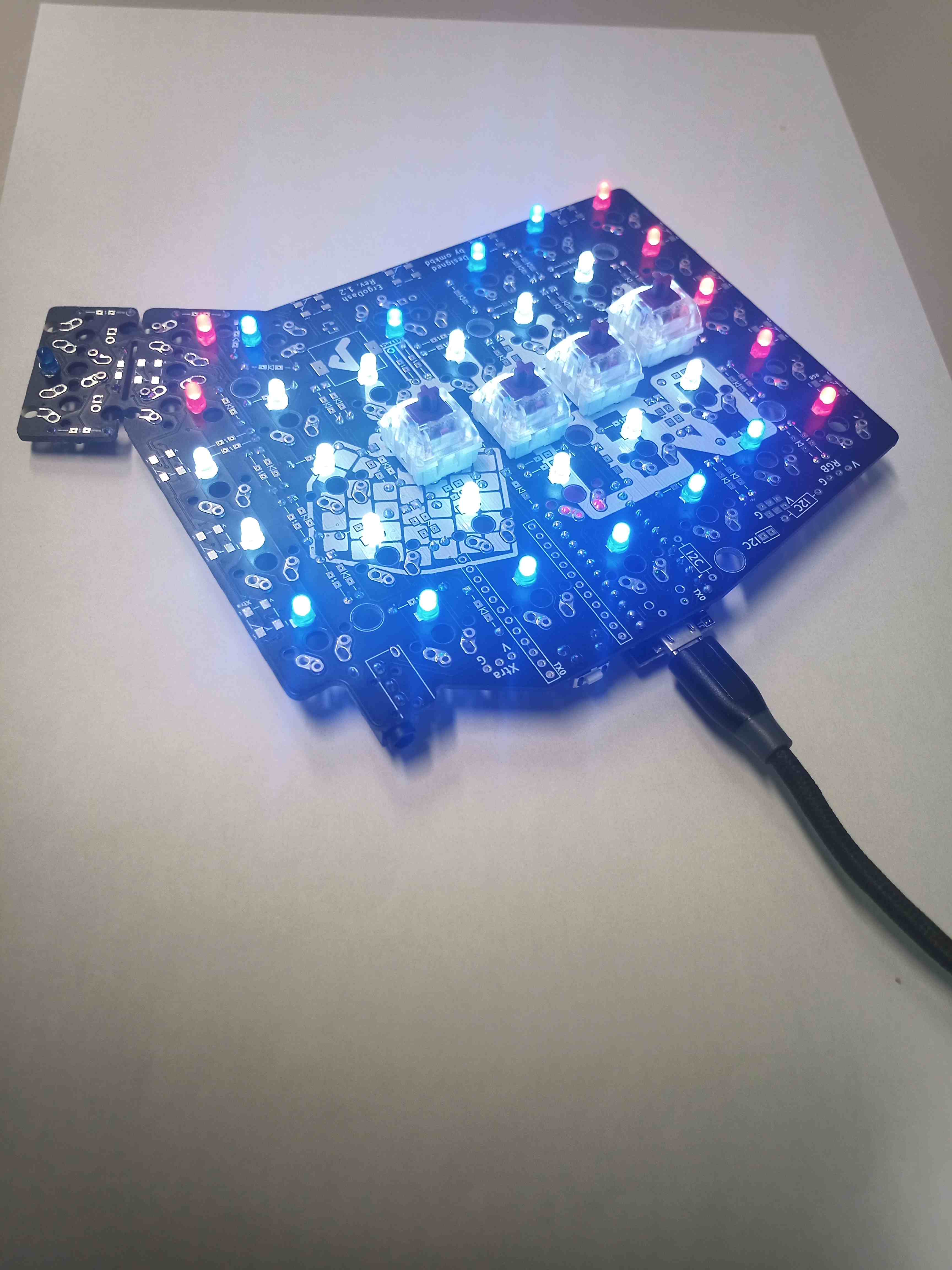
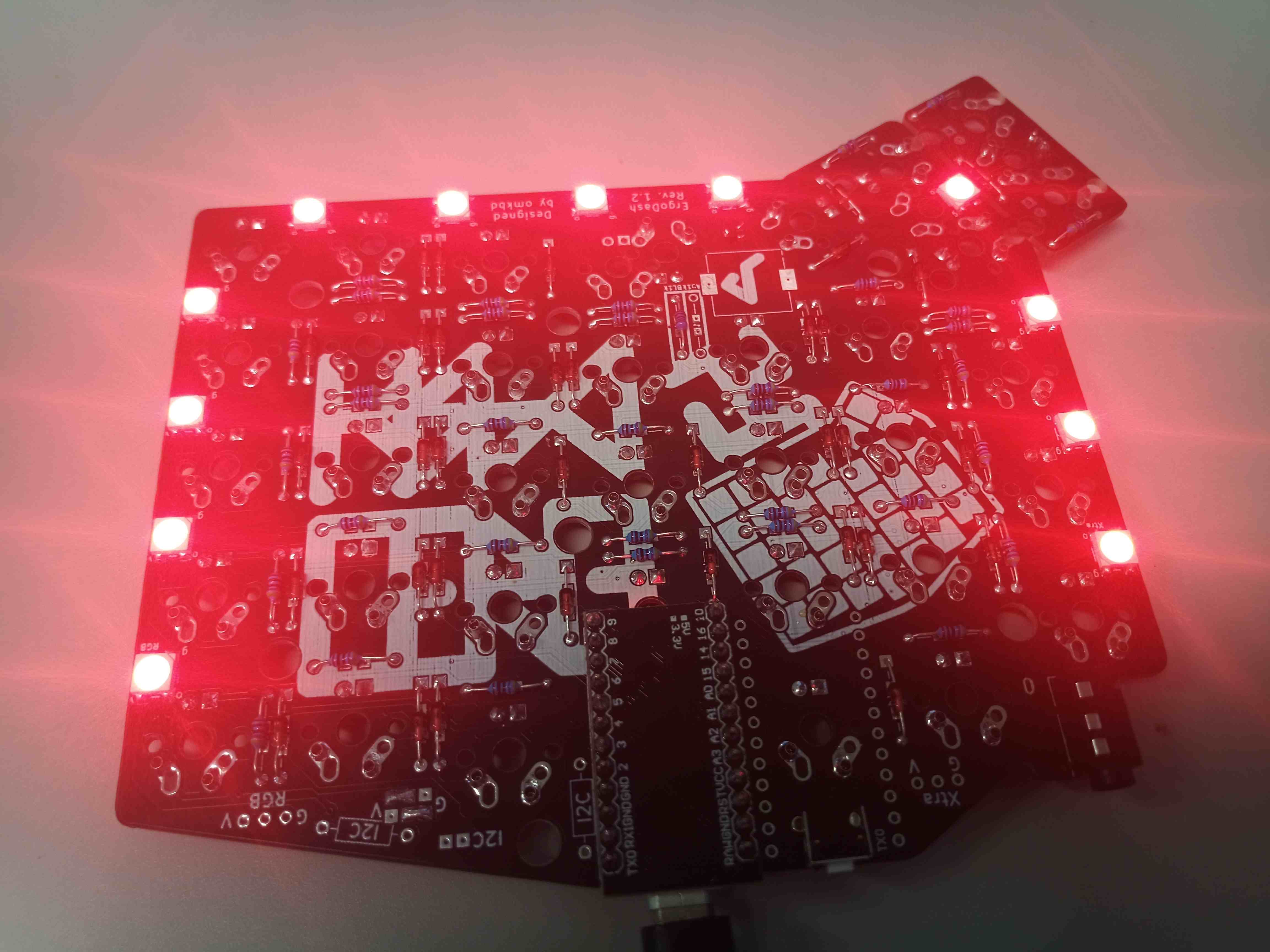
8.5 Testing the boards
At this point, it should probably be better to test the board to make sure that it works, and fix up the potential flaws before assembling the case. It might be useful to flash the firmware at this step and set up a few keys to check that the RGB under low and backlight LEDs work and that keystrokes are registered. For this build, wacky initial soldering of the pro micro pins resulted in only a few RGB under glow LED working at the same time, so it was easier to just fix it during this testing phase, rather than disassembling the whole case, which might not even be possible if you are not using hot swapping. Also had to change a LED that was not working out of the box.
9. Case assembly
No particular comment here. Note, however, that the upper side of the case must be installed before even inserting and soldering the switches, so the order is really important.
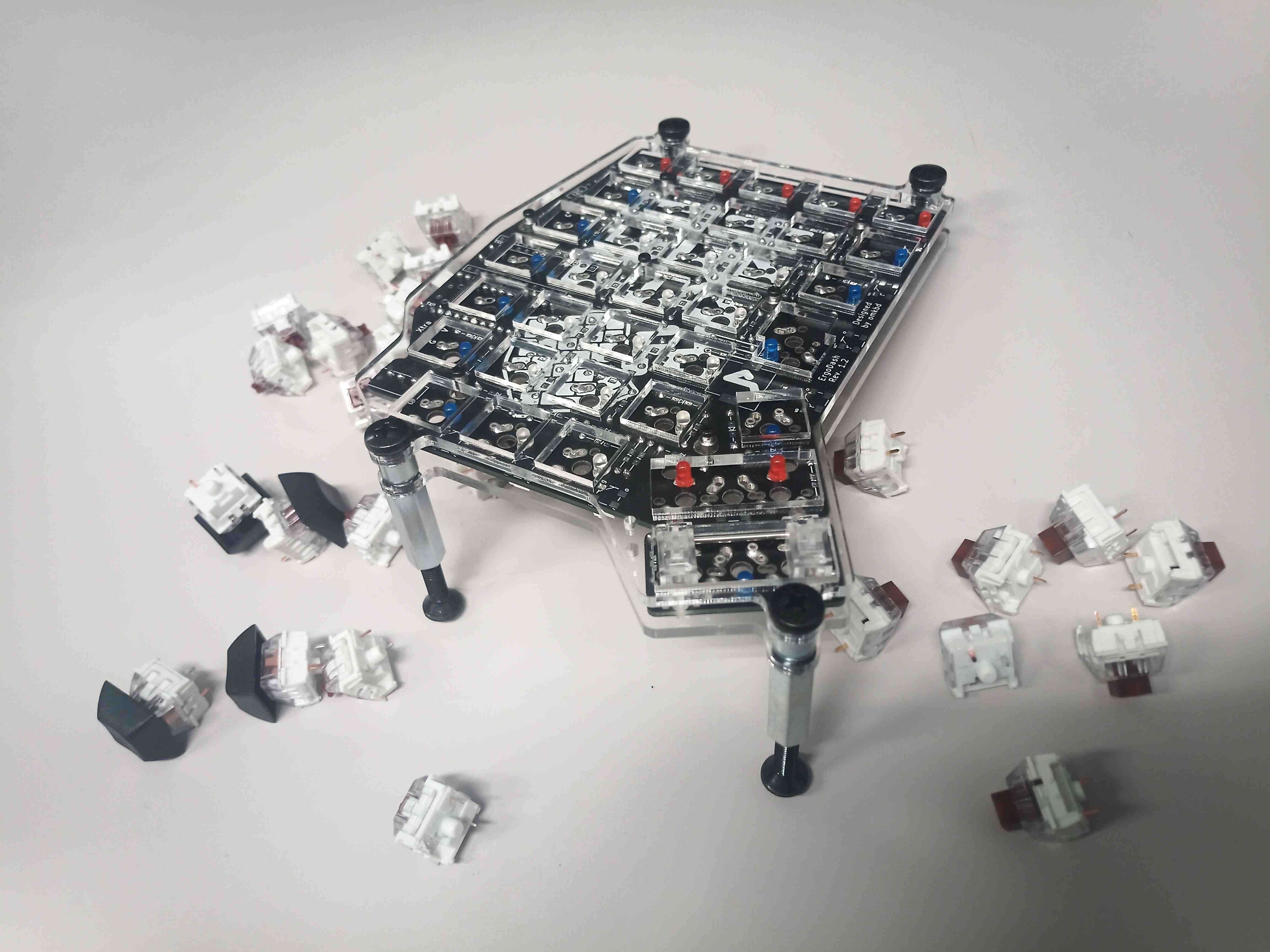
10. Tenting screws assembly and switch mounting
Last but not least, the screws and standoff for the tenting solutions can be set, with a cushion pad on the bottom to not ruin the desk. Another mistake when ordering the screws was failing to take into account the additional 3mm thickness of the smallest part of the case added, and ending up with 4 screws of the appropriate length (16mm) missing. Besides that, the key switches can be easily installed or removed thanks to the hot-swapping support.
Firmware Flash Notes
2022-05 Update: Elite-C Firmware flashing with handedness support.
After upgrading to an Elite-C MCU and getting more familiar with the QMK firmware, I found a more elegant method to flash the firmware that even takes into account the handedness of the connected keyboard. The process can be defined as follows.
After cloning the QMK firmware to the local file system and copying the default profile for the ergodash/rev1 keyboard, the default configuration is set as follows:
qmk config

general.color=True
general.datetime_fmt=%Y-%m-%d %H:%M:%S
general.log_file_fmt=[%(levelname)s] [%(asctime)s] [file:%(pathname)s] [line:%(lineno)d] %(message)s
general.log_file_level=info
general.log_fmt=%(levelname)s %(message)s
general.unicode=True
general.verbose=False
user.keyboard=ergodash/rev1
user.keymap=dosssman
user.qmk_home=/path/to/qmk_firmware``
Next, make sure either avrdude (for Pro Micro) or dfu (Elite-C) drives are installed using qmk info.
1. Make sure the bootloader used is atmel-dfu in qmk_firmware/keyboards/ergodash/rules.mk as follows:
# MCU name
MCU = atmega32u4

# Bootloader selection
# BOOTLOADER = caterina # For Pro-Micro
BOOTLOADER = atmel-dfu # For Elite-C
This is a critical step.
2. In qmk_firmware/ergodash/rev1/keymaps/dosssman/config.h, we set:
#define EE_HANDS
instead of the default MASTER_LEFT or MASTER_RIGHT.
3. Assuming the QMK configurator was used to generate a keymap.json like file, the corresponding keymap.c can be generated using:
qmk json2c keymap.json > keymap.c
The keymap.c needs to be placed to the qmk_firmware/keyboards/ergodash/rev1/keymaps/dosssman/ directory.
4. From the qmk_firmware root directory, run the command corresponding to the side of the board that is currently connected:
make ergodash/rev1:dosssman:dfu-split-left # For the left side
or
make ergodash/rev1:dosssman:dfu-split-right # For the right side
Before doing anything else, We can use this step to make sure that the atmel-dfu was properly selected earlier.
Namely, the terminal should mention “DFU” while prompting you to press the reset button on the keyboard.
2022-05 Update: Pro Micro Firmware flashing with handedness support (Untested)
This should be similar to the firmware flashing process for the Elite-C.
1. Make sure the boot loader used is caterina in qmk_firmware/keyboards/ergodash/rules.mk as follows:
# MCU name
MCU = atmega32u4

# Bootloader selection
BOOTLOADER = caterina # For Pro-Micro
# BOOTLOADER = atmel-dfu # For Elite-C
2. In qmk_firmware/ergodash/rev1/keymaps/dosssman/config.h, we set:
#define EE_HANDS
3. Assuming the QMK Configurator was used to generate a keymap.json like file, the corresponding keymap.c can be generated using:
qmk json2c keymap.json > keymap.c
The keymap.c needs to be placed to the qmk_firmware/keyboards/ergodash/rev1/keymaps/dosssman/ directory.
4. From the qmk_firmware root directory, run the command corresponding to the side of the board that is currently connected:
make ergodash/rev1:dosssman:avrdude-split-left # For the left side
or
make ergodash/rev1:dosssman:avrdude-split-right # For the right side
Pro Micro: a bit old and amateurish method for flashing
After installing the QKM Toolbox, clone the [qmk_firmware] repository somewhere on the hard drive. (Current procedure assumes Linux system.)
Then, after accessing said repository’s directory via the command line, running qmk setup will set that working directory (the previously cloned qmk firmware folder) will set it as the default folder qmk will compile and flash keymaps from.
Additionally, setting the following configuration variable saves us some time downstream.
qmk config user.keyboard=ergodash/rev1

qmk config user.keymap=dosssman
Next, as suggested by the last command above, we need the corresponding dosssman keymap folder, which has to be created in /path/to/qmk_firmware/keyboards/ergodash/rev1/keymaps/.
For convenience, copying the default folder in that same .../ergodash/rev1/keymaps/ folder, then renaming it the profile name (dosssman in this case) is recommended.
Next comes the layout configuration, which can be done either using the QMK Online Configurator or the GUI QMK Toolbox provided for Windows and macOS systems.
Once the layout is configured, and the corresponding .json configuration file downloaded, the Pro Micro can be flashed by running
qmk flash /path/to/keymap_configuration.json
# Note: this assumes the user.keyboard and user.keymap config variables are configured,
# otherwise they need to be specified using the corresponding arguments
When mapping mouse keys, the appropriate build rules had to be updated in the .../qmk_firmware/keyboards/ergodash/rev1/keymaps/dosssman/rules.mk file.
The content as of the final version I use (Mouse and Extra Keys enabled) is as follows:
BACKLIGHT_ENABLE = yes
RGBLIGHT_ENABLE = yes
AUDIO_ENABLE = no
EXTRAKEY_ENABLE = yes
MOUSEKEY_ENABLE = yes
Note that with the EXTRA_KEY set to yes, one can configure the keyboard itself to switch either the backlight or the underglow directly, using a combination of keys.
And that is pretty much it.
Leave a comment