
Charybdis Build Log
Short version
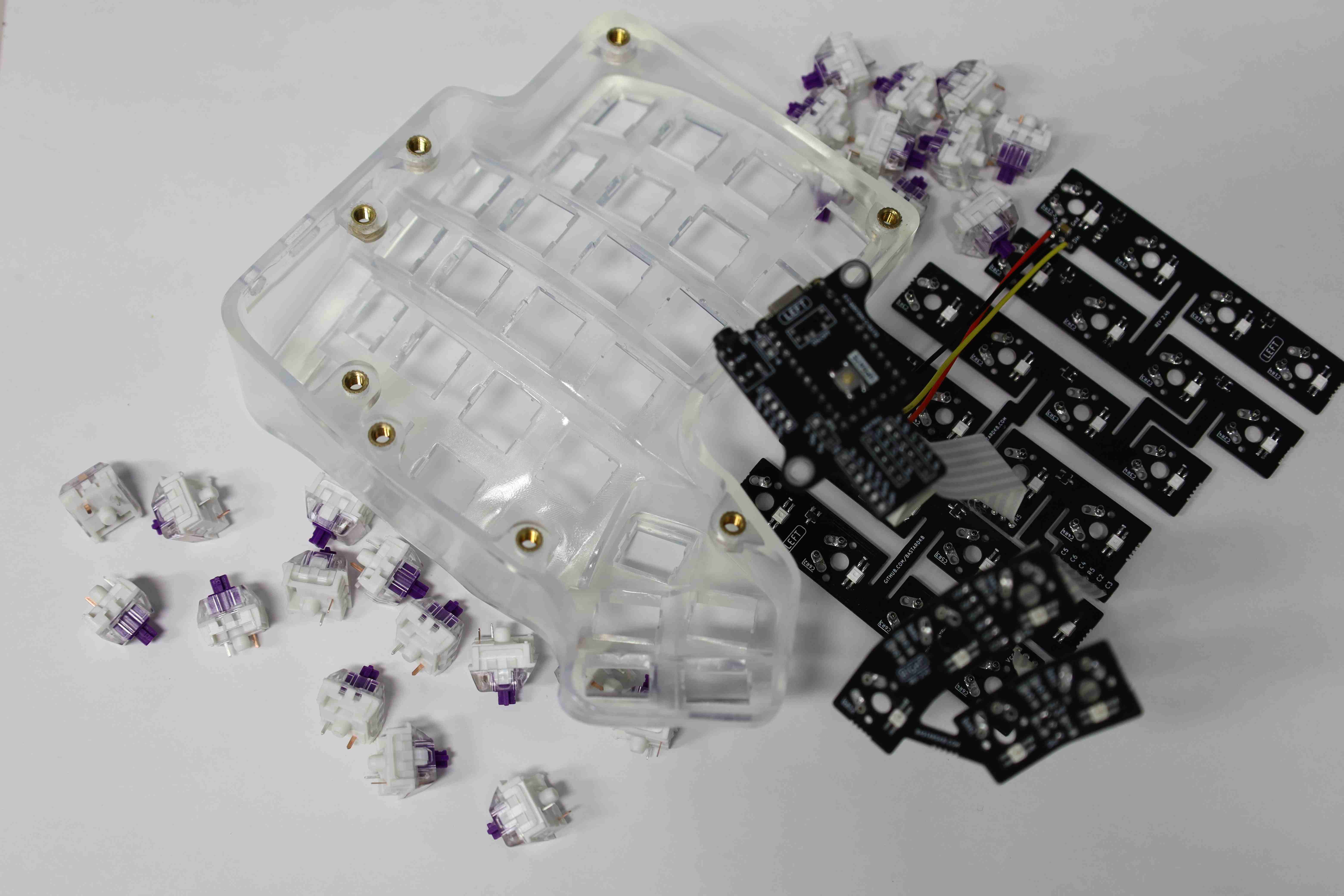
This write-up will focus on the most important points of the build and showcase the final result.
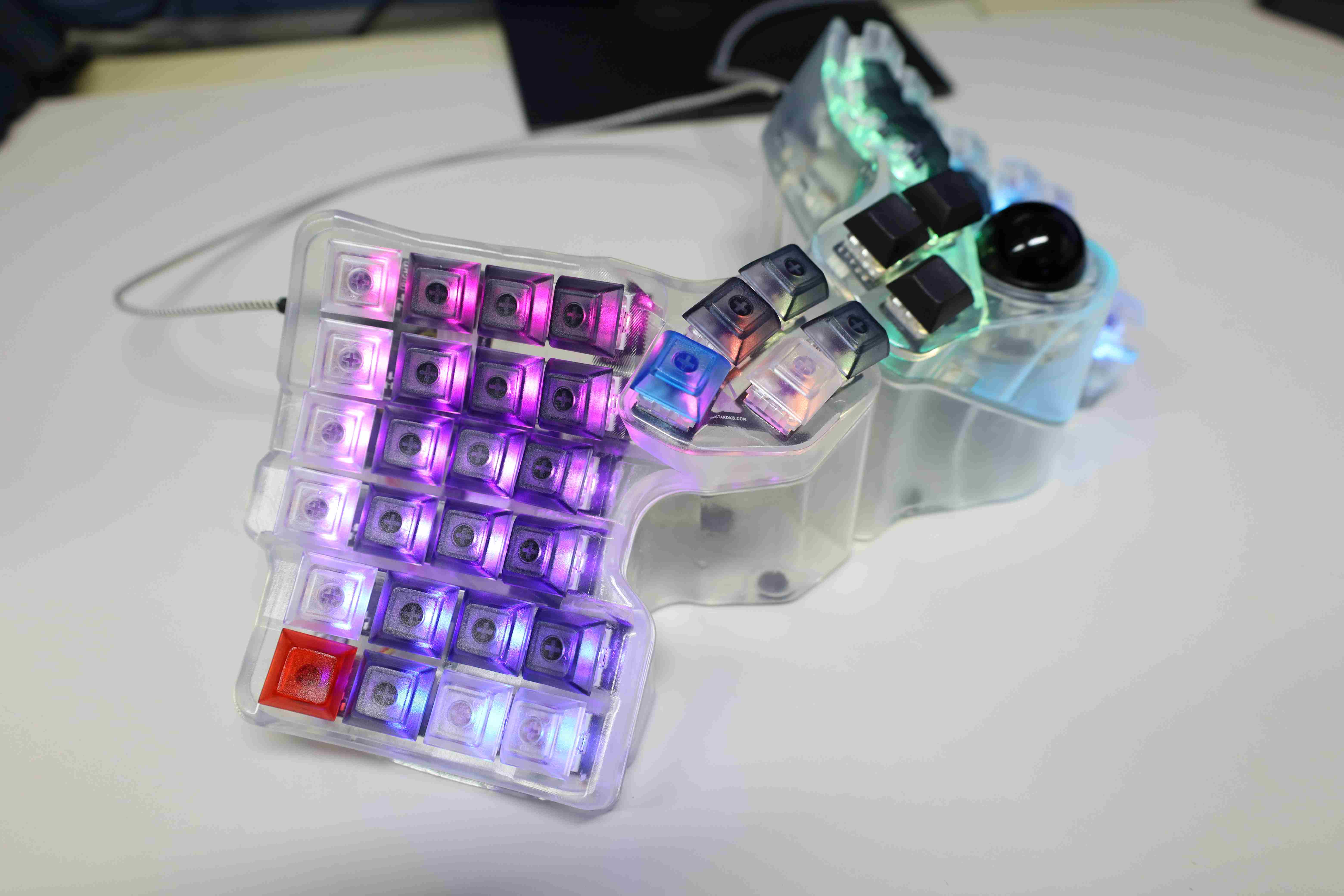
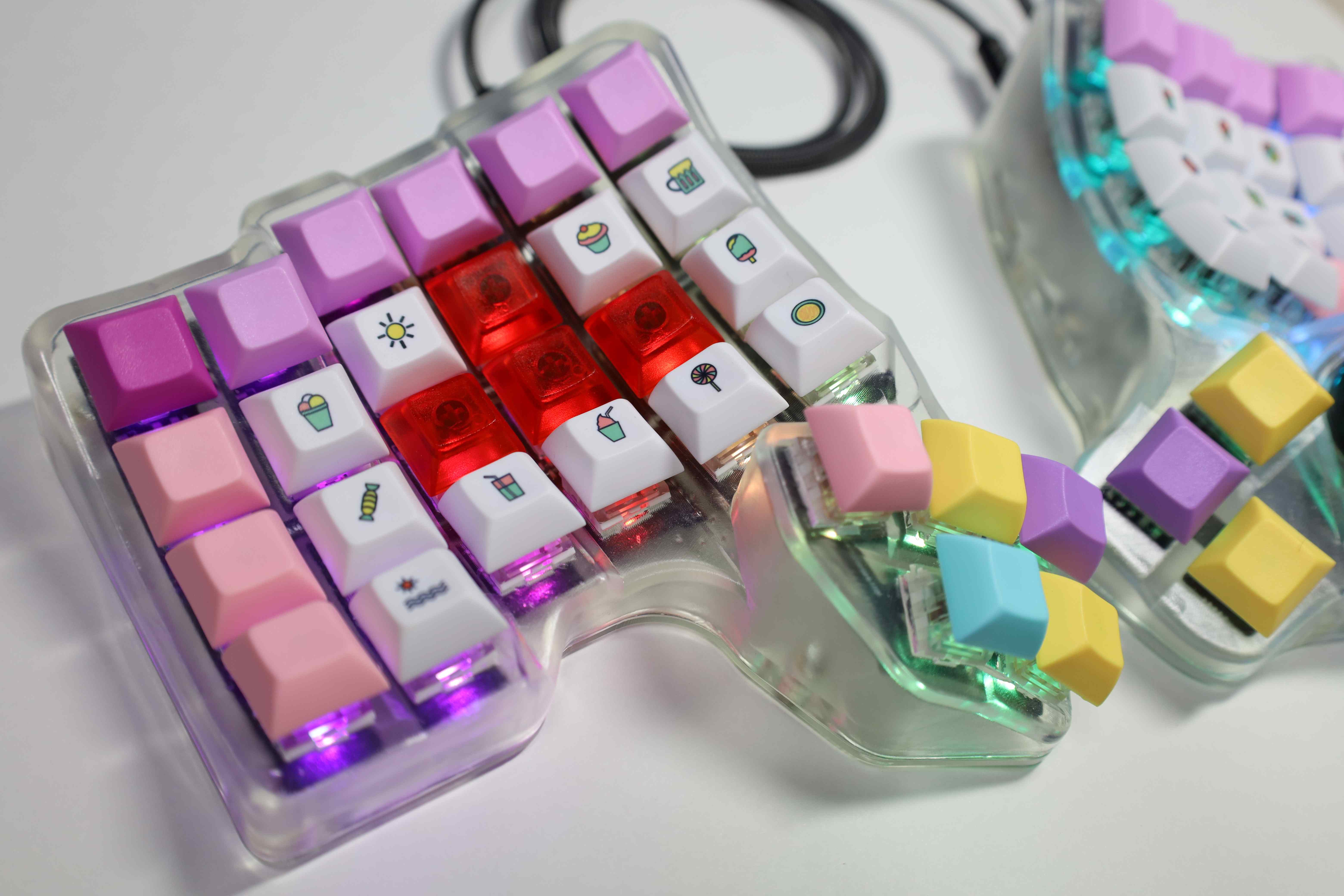
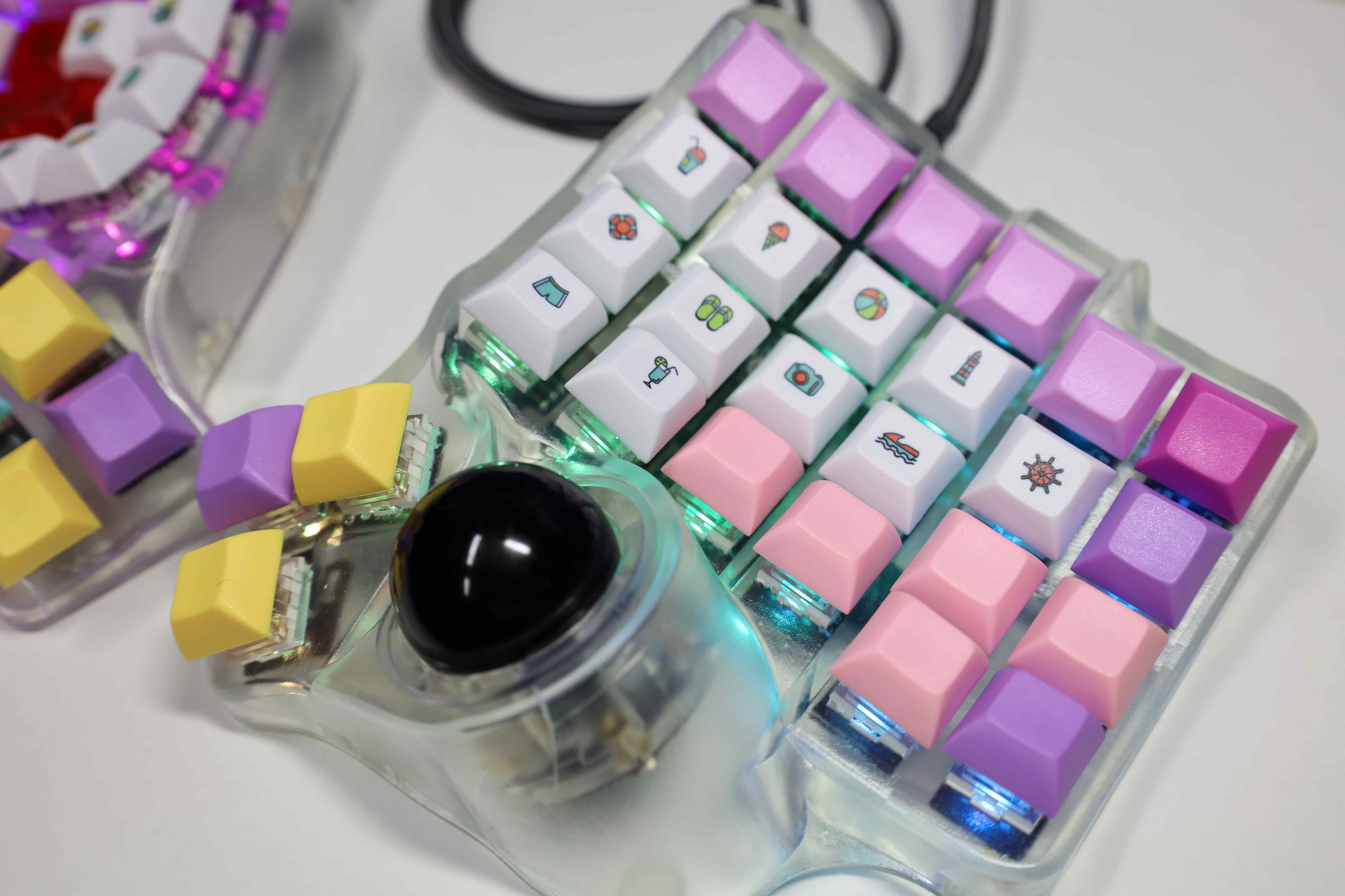
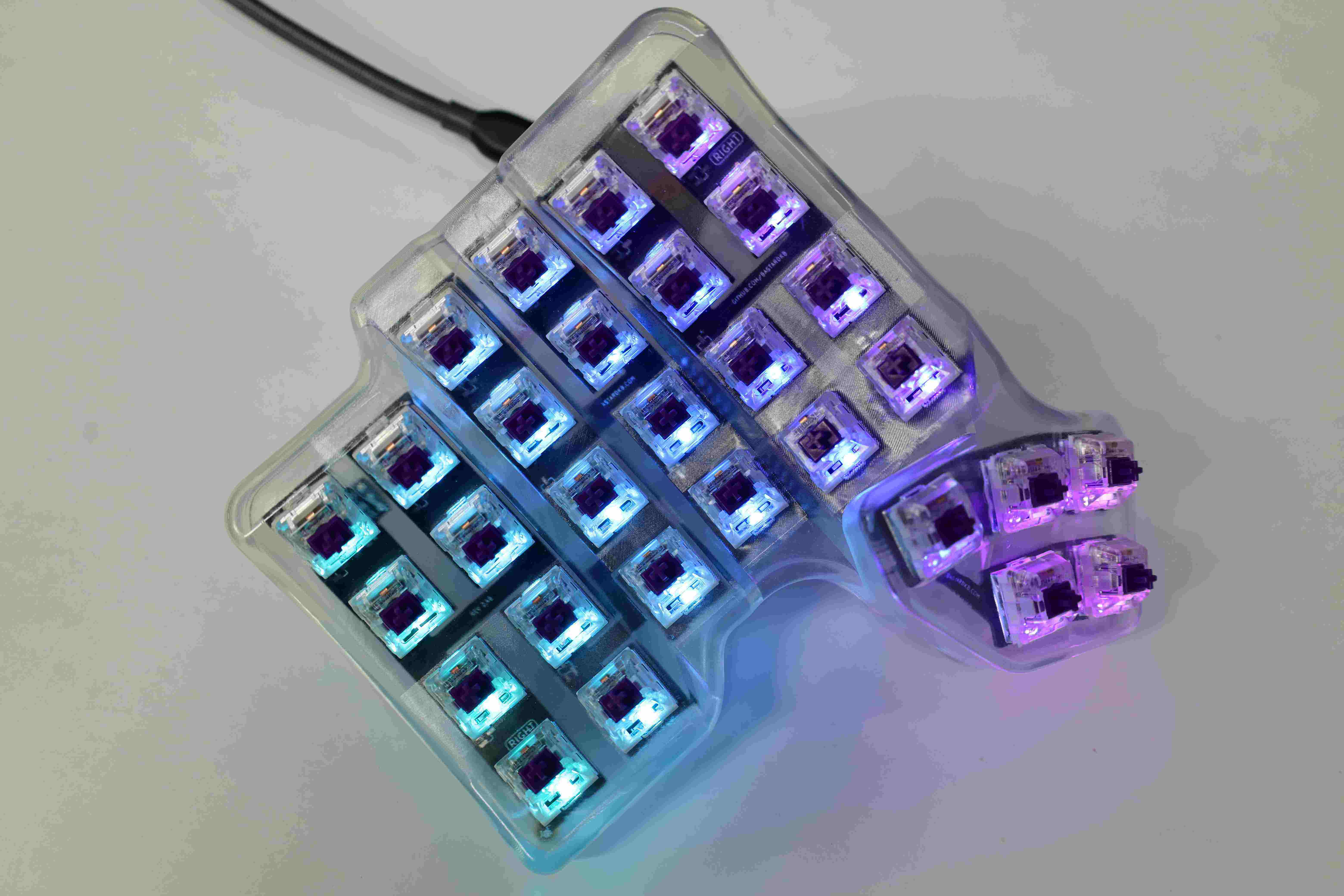
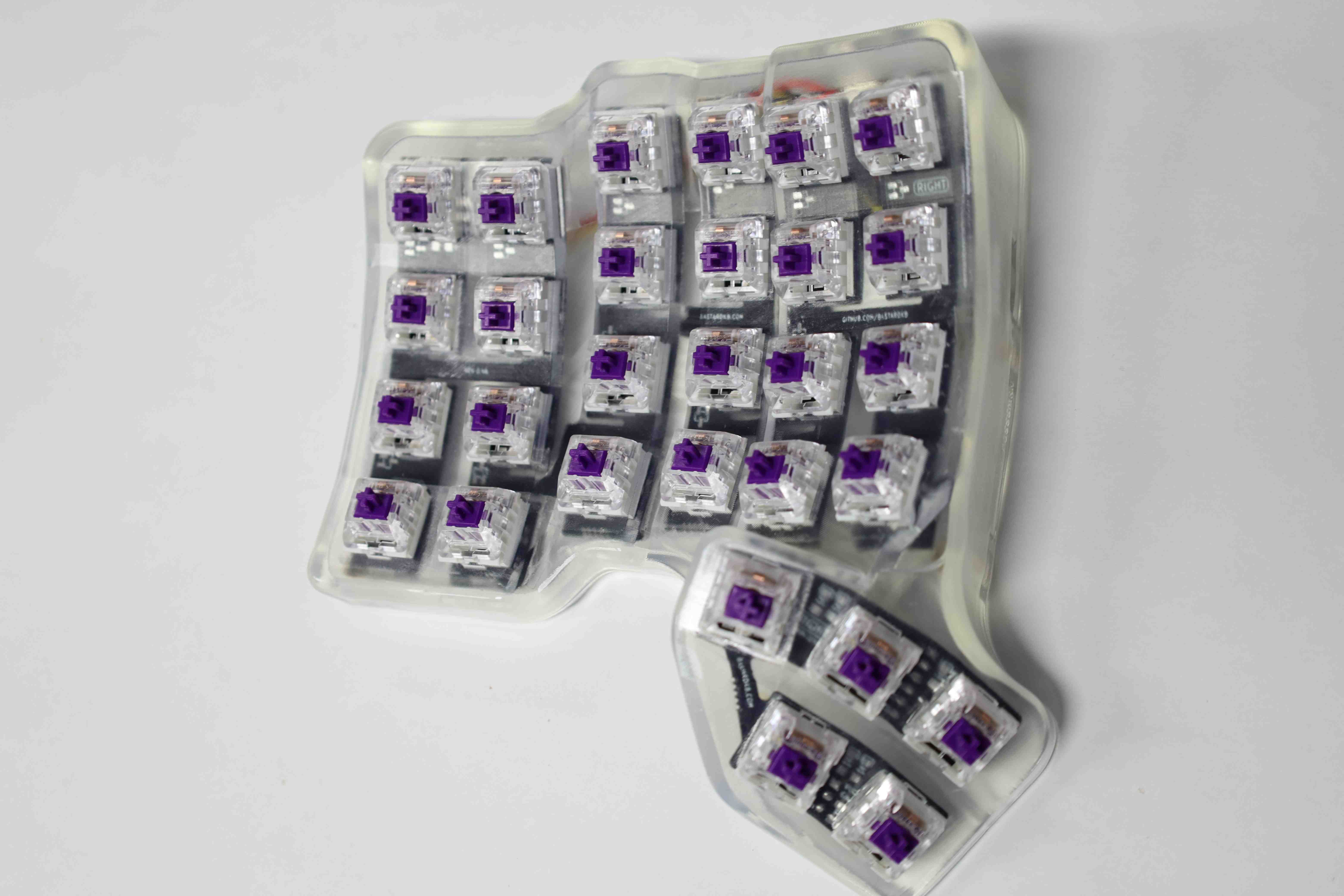
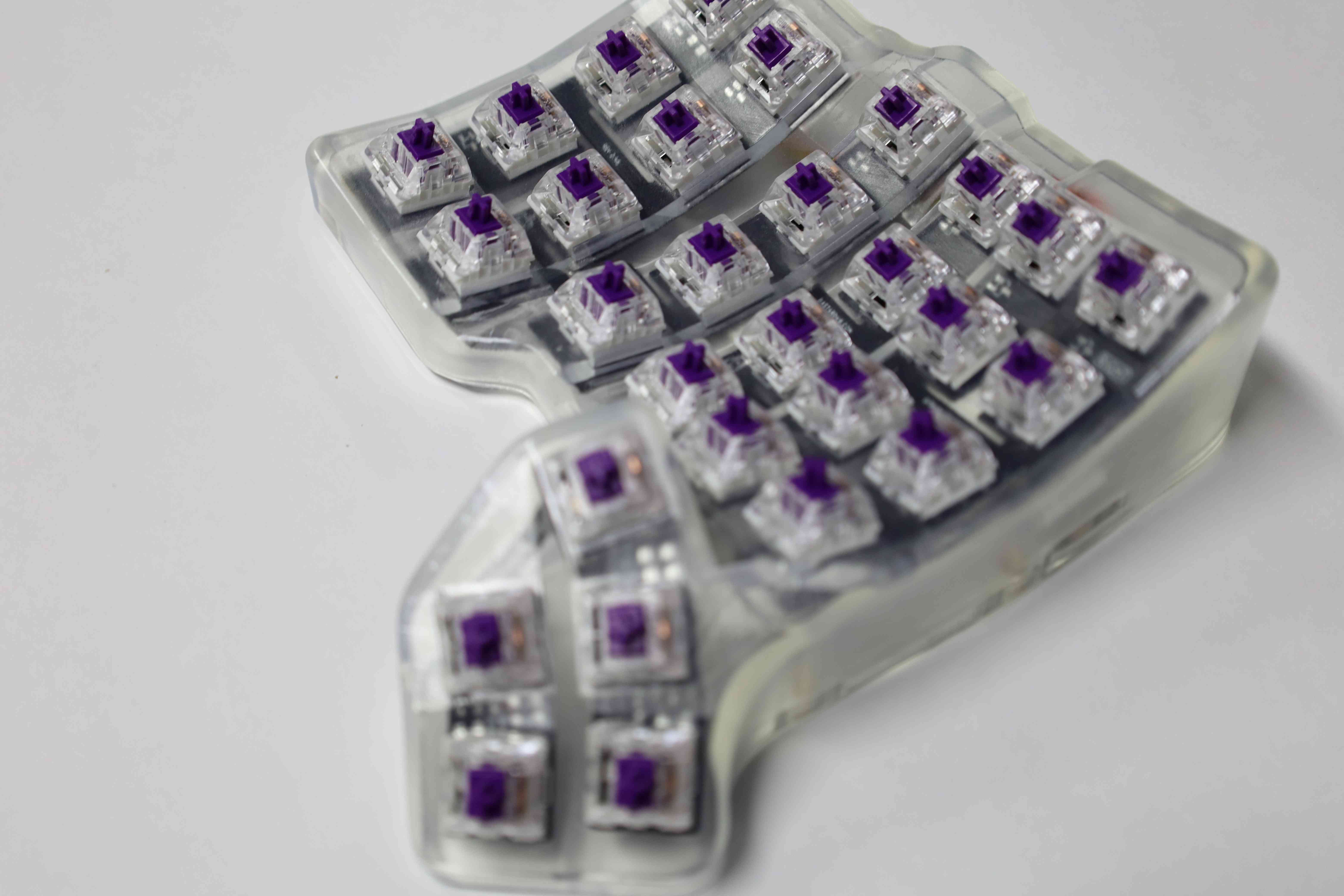
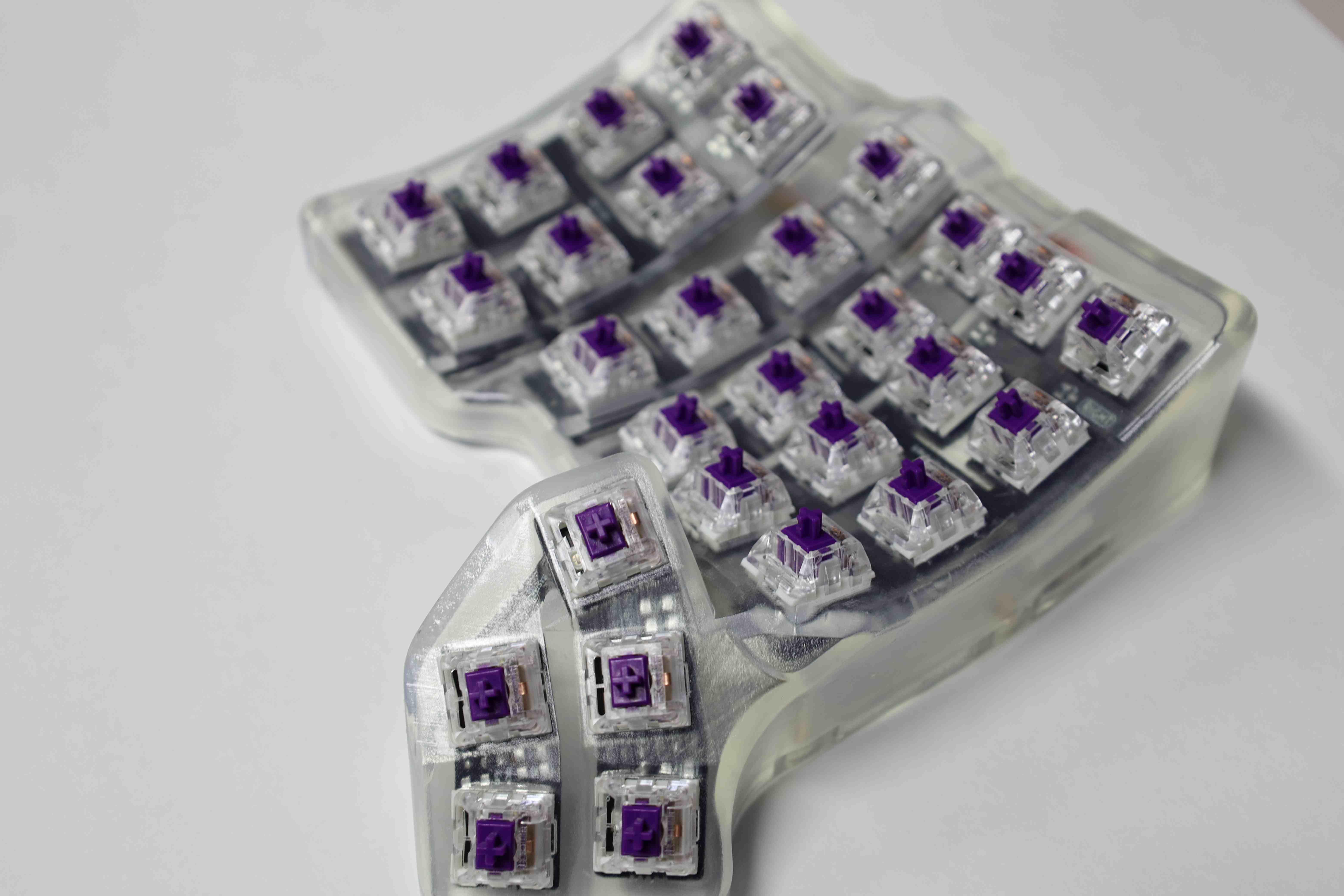
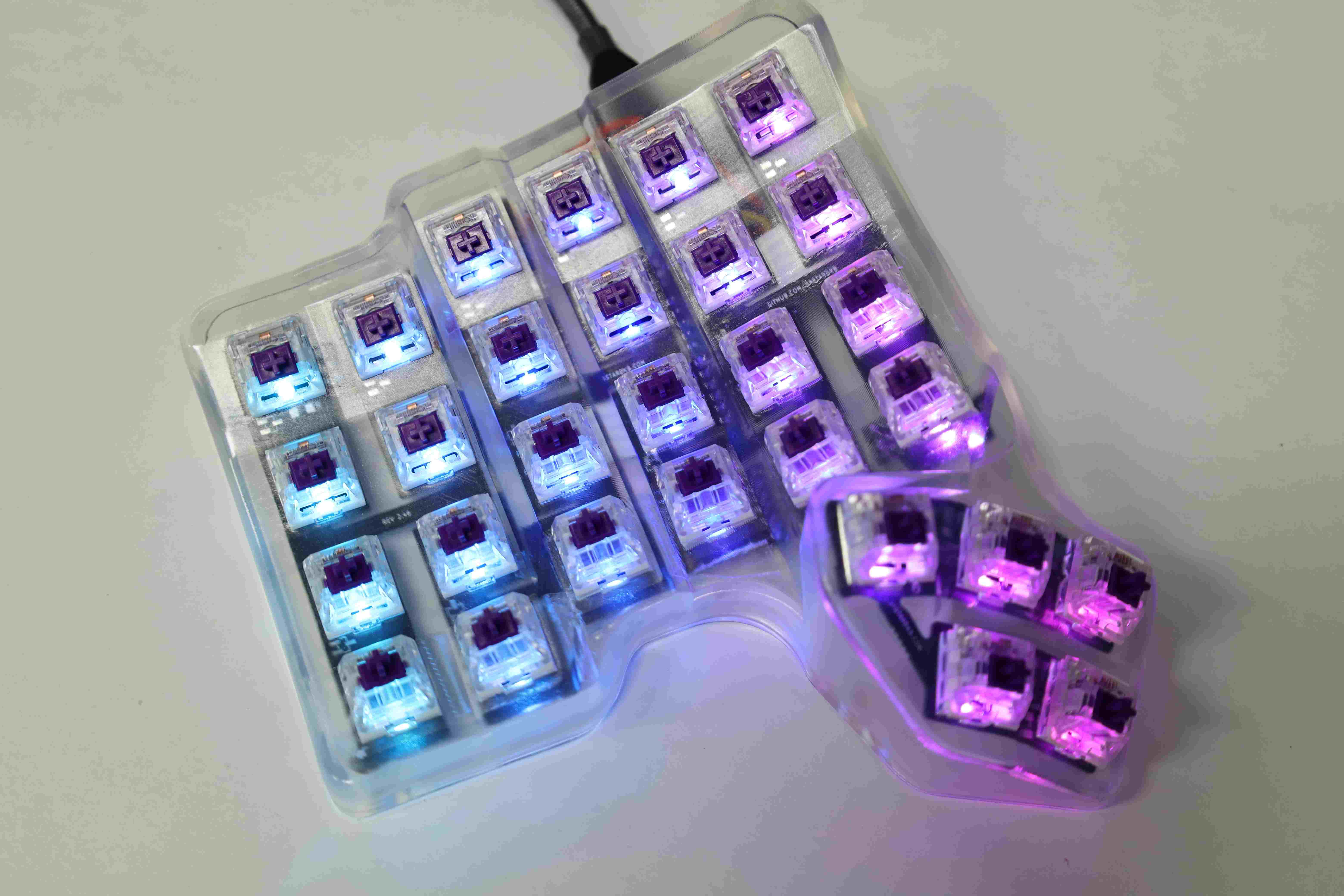
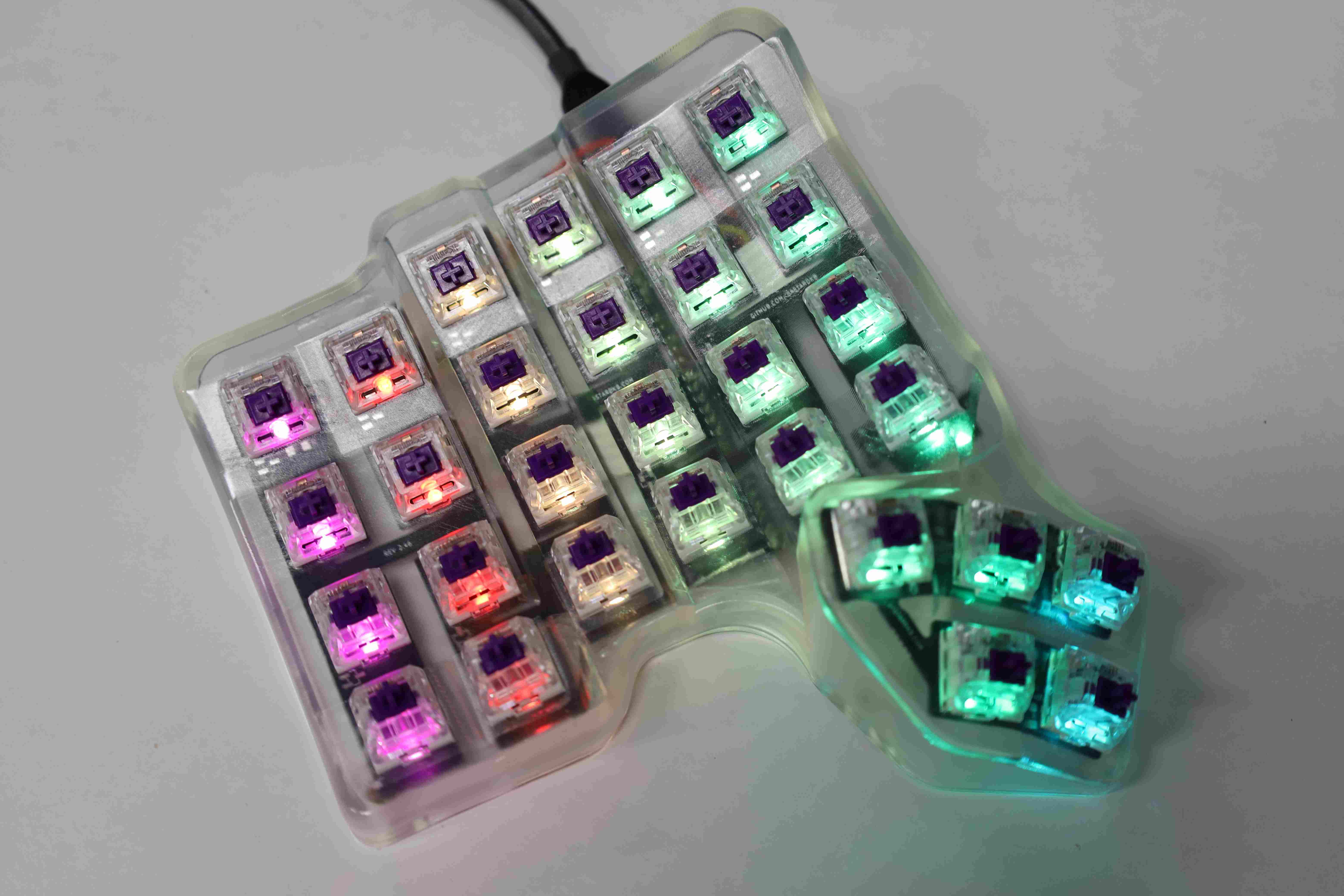
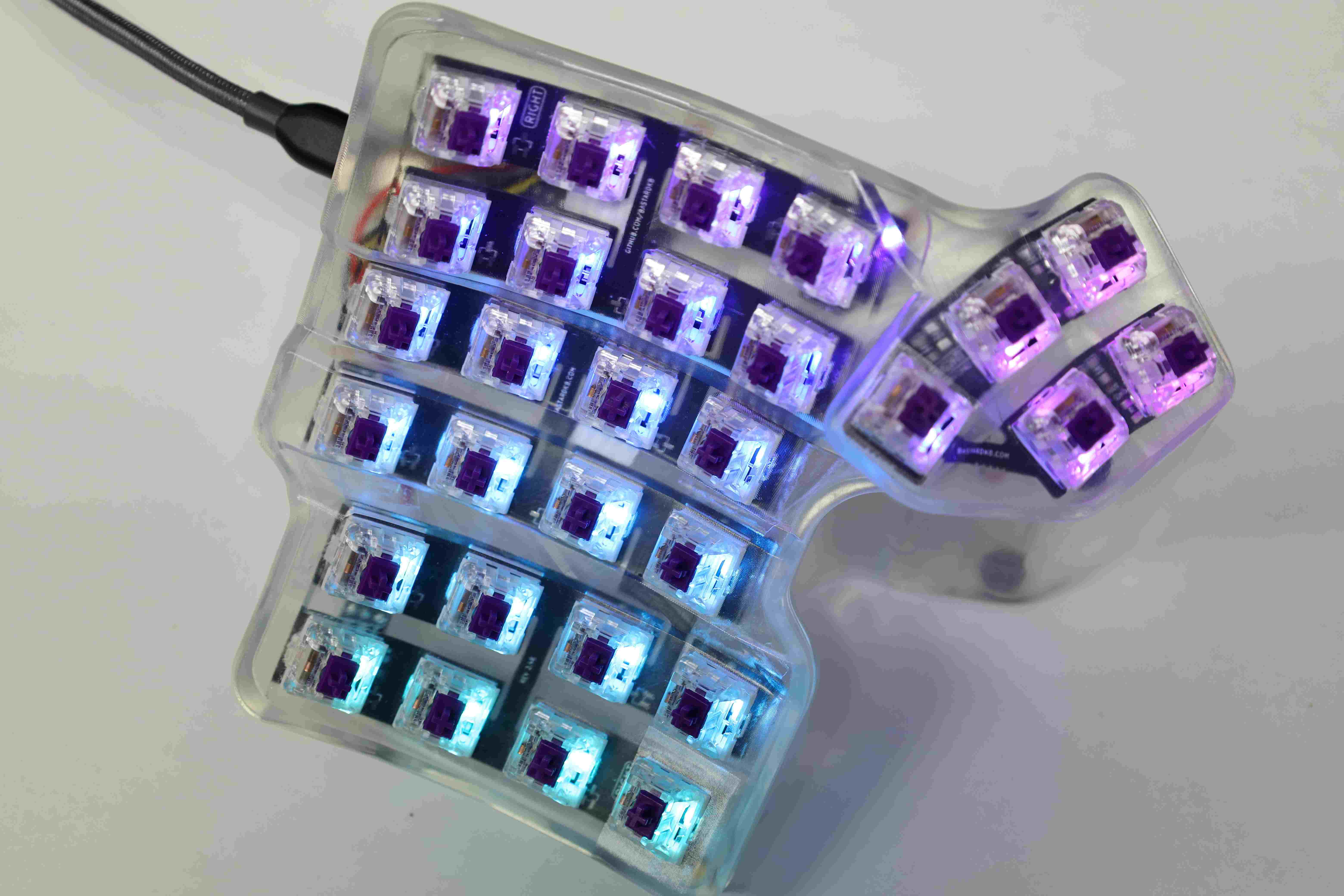
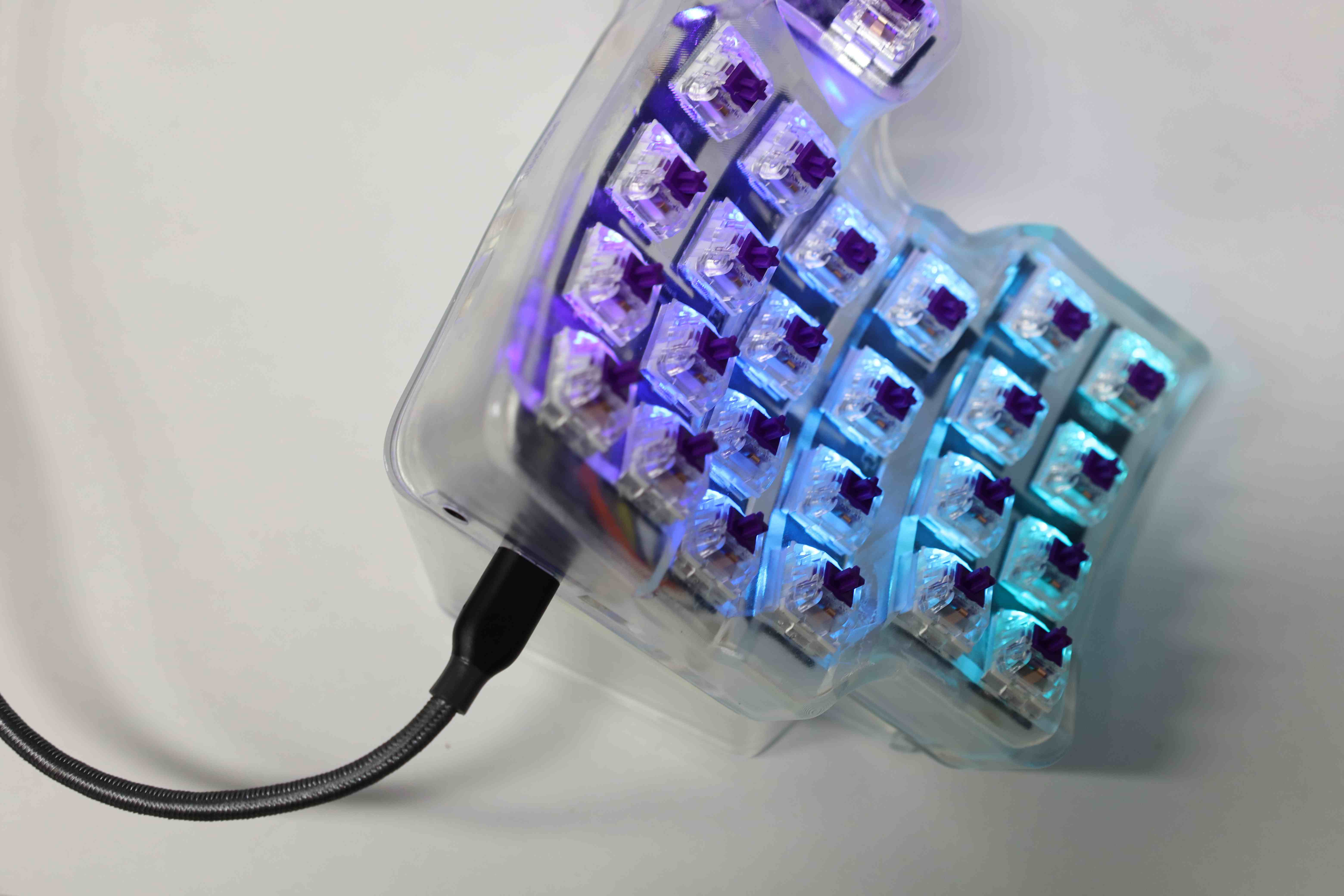
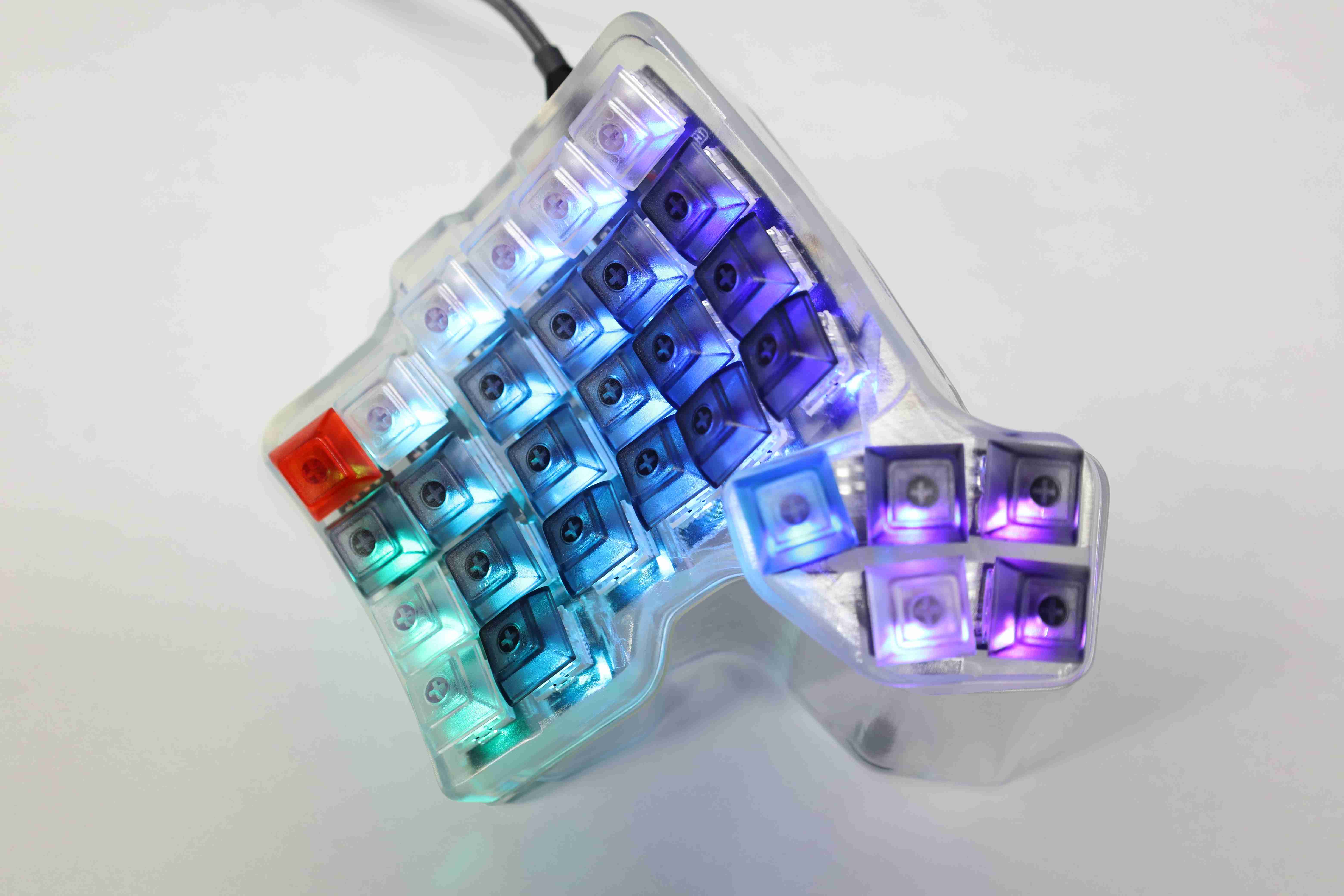
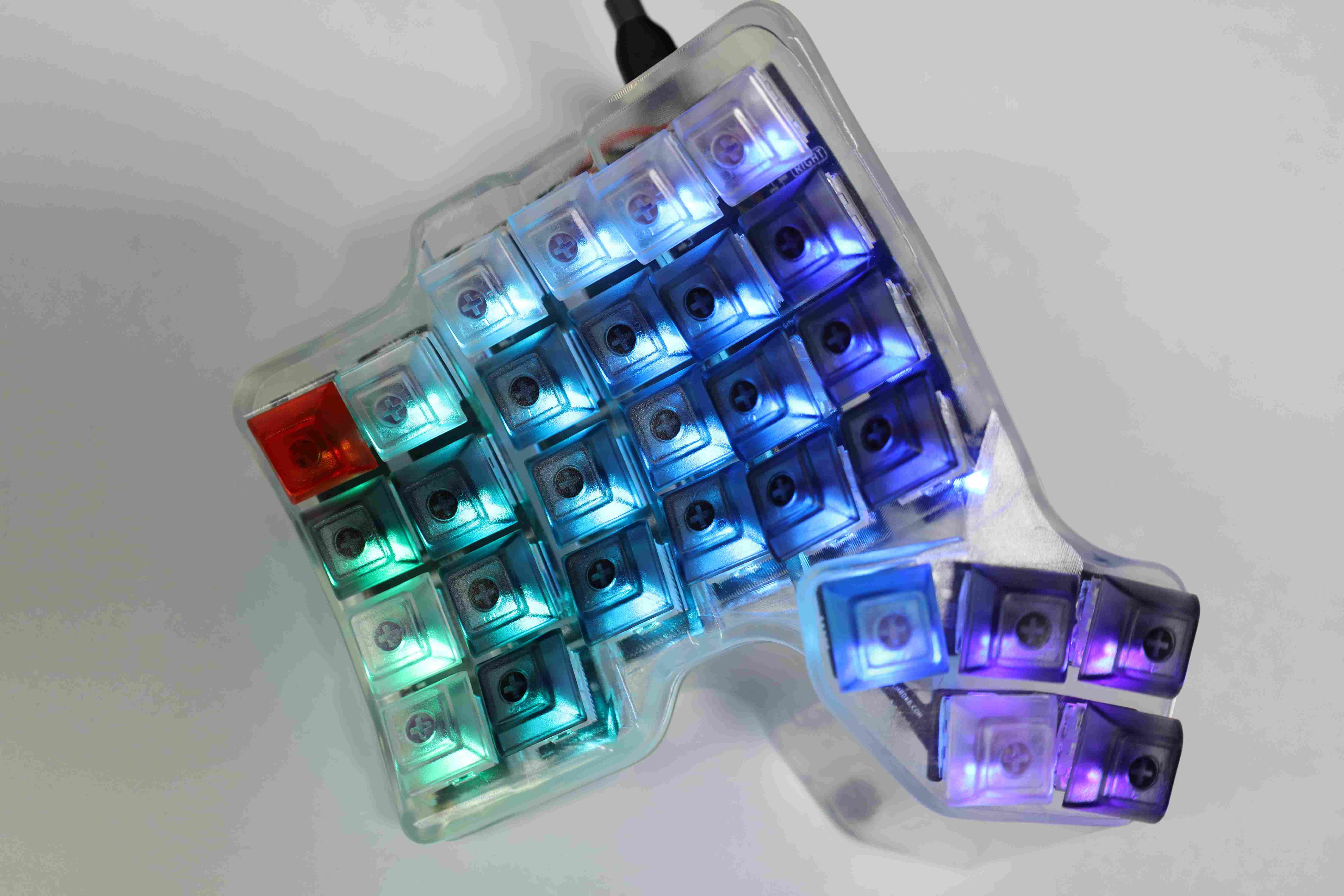
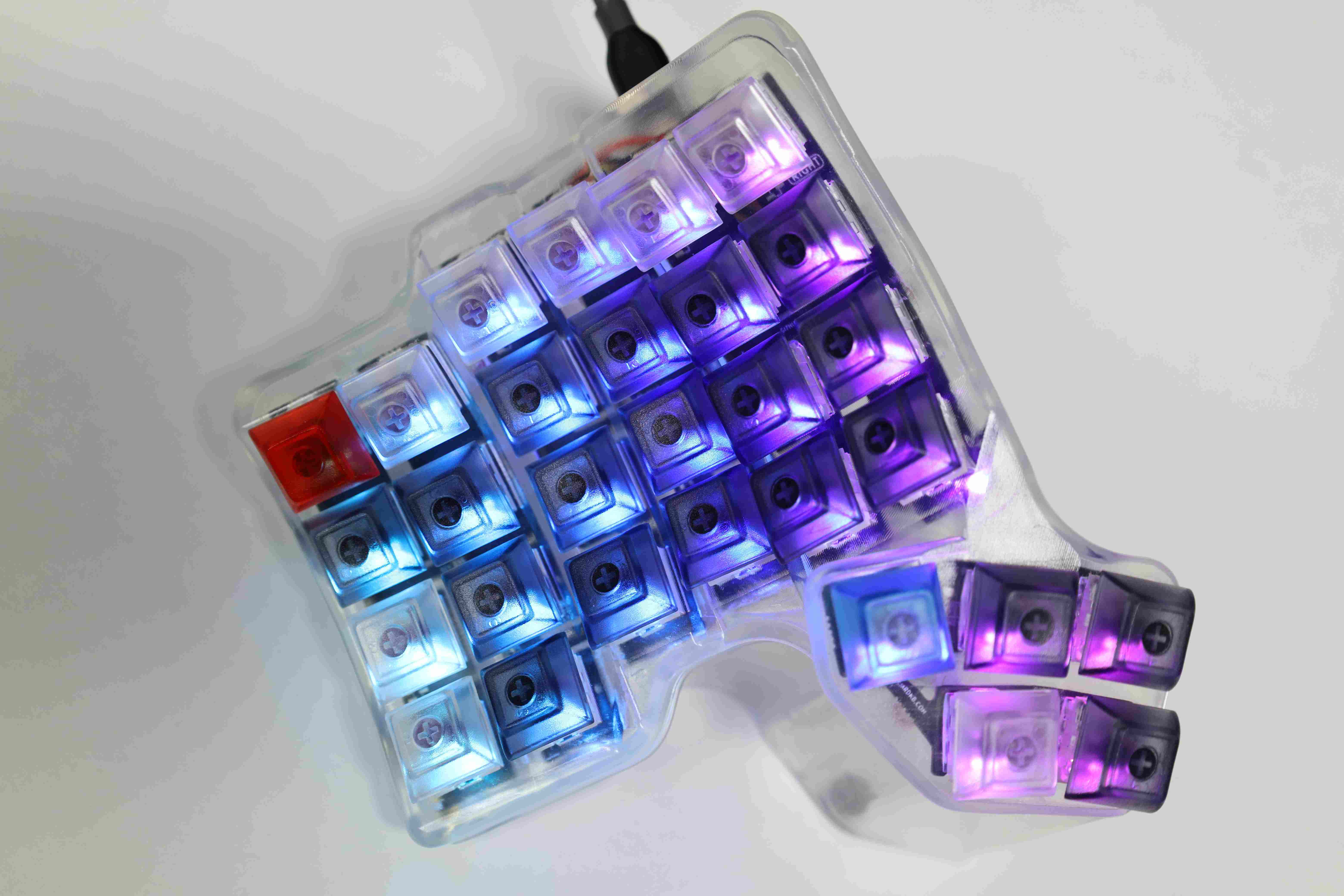
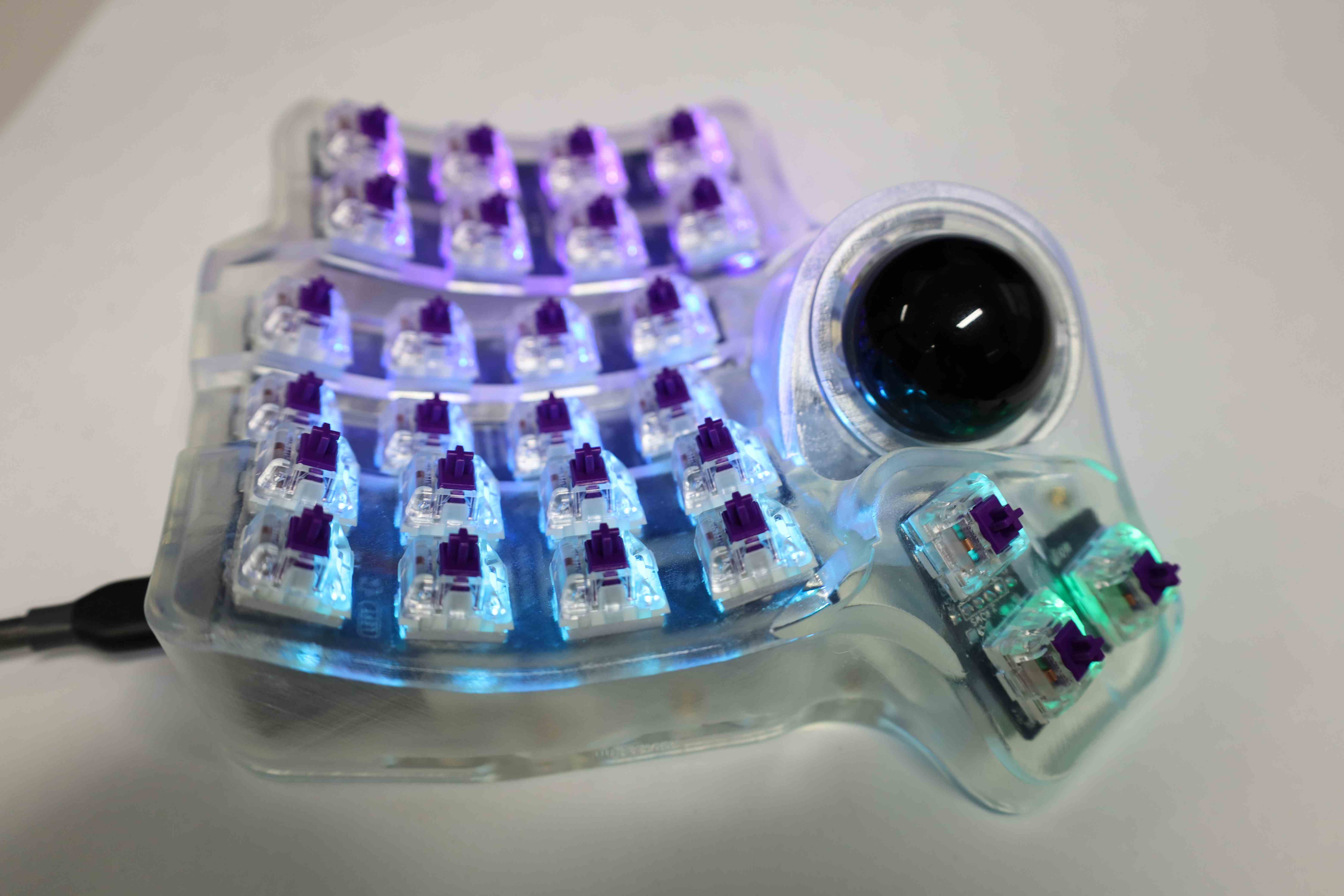
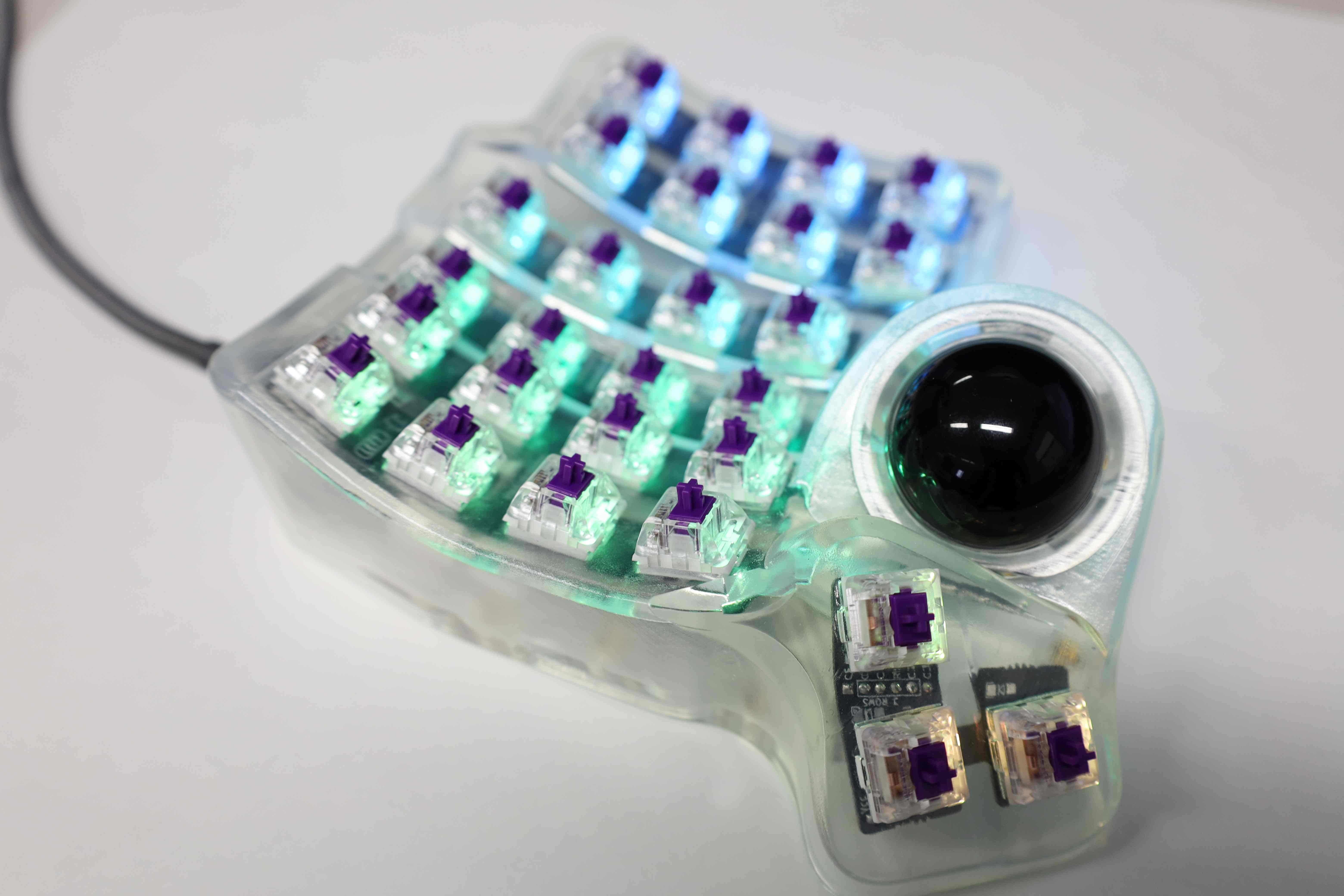
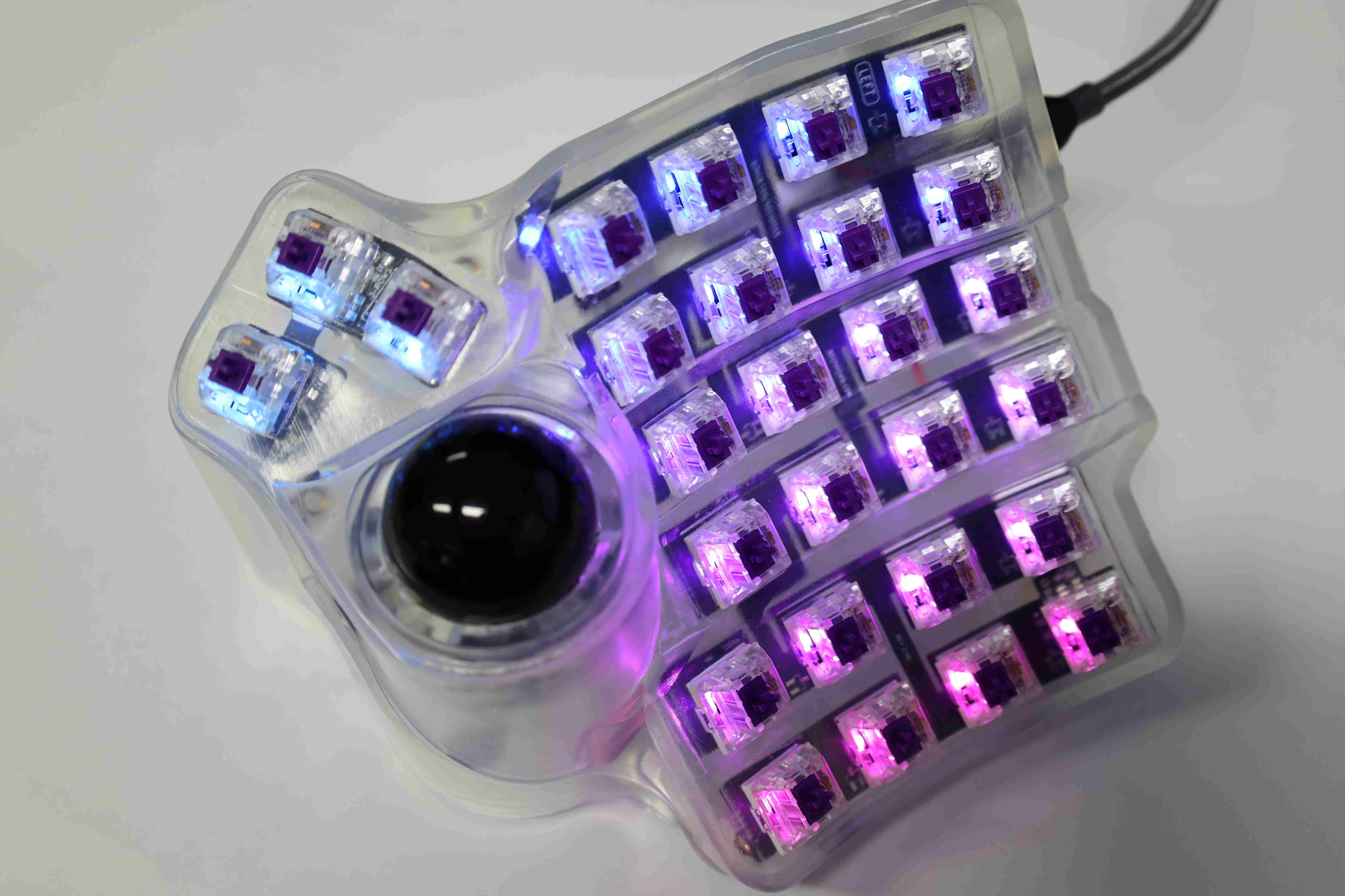
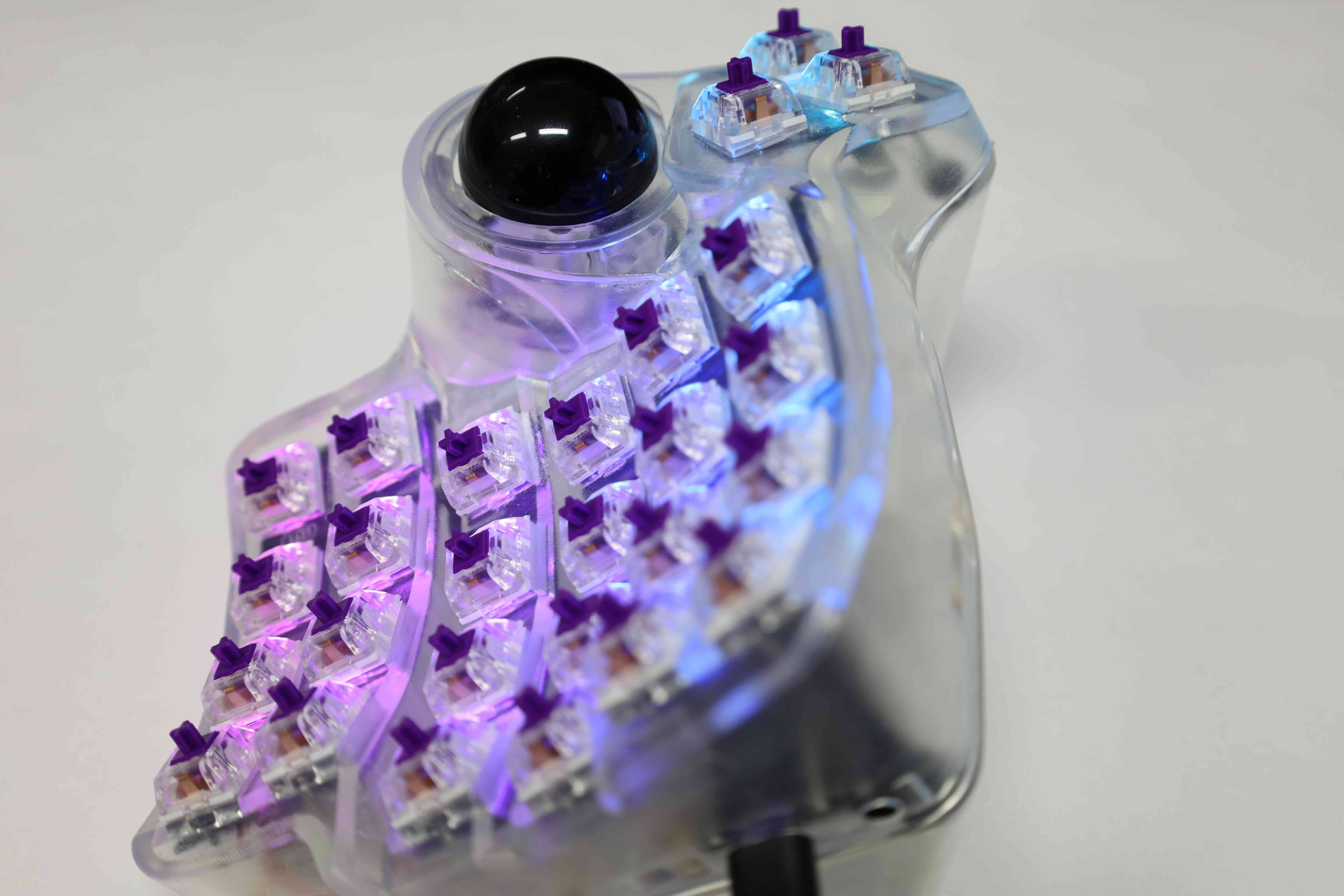
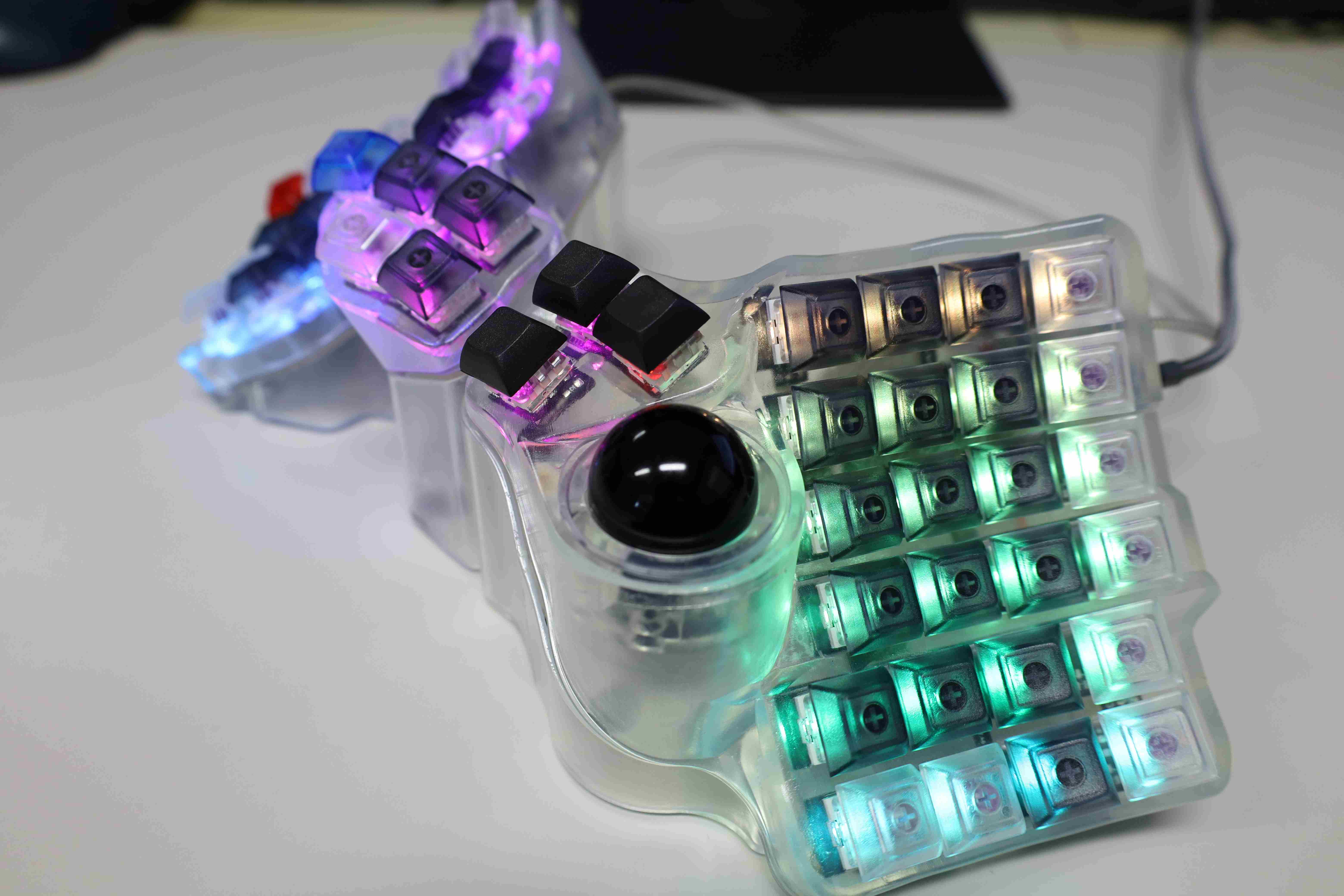
Showcase #1
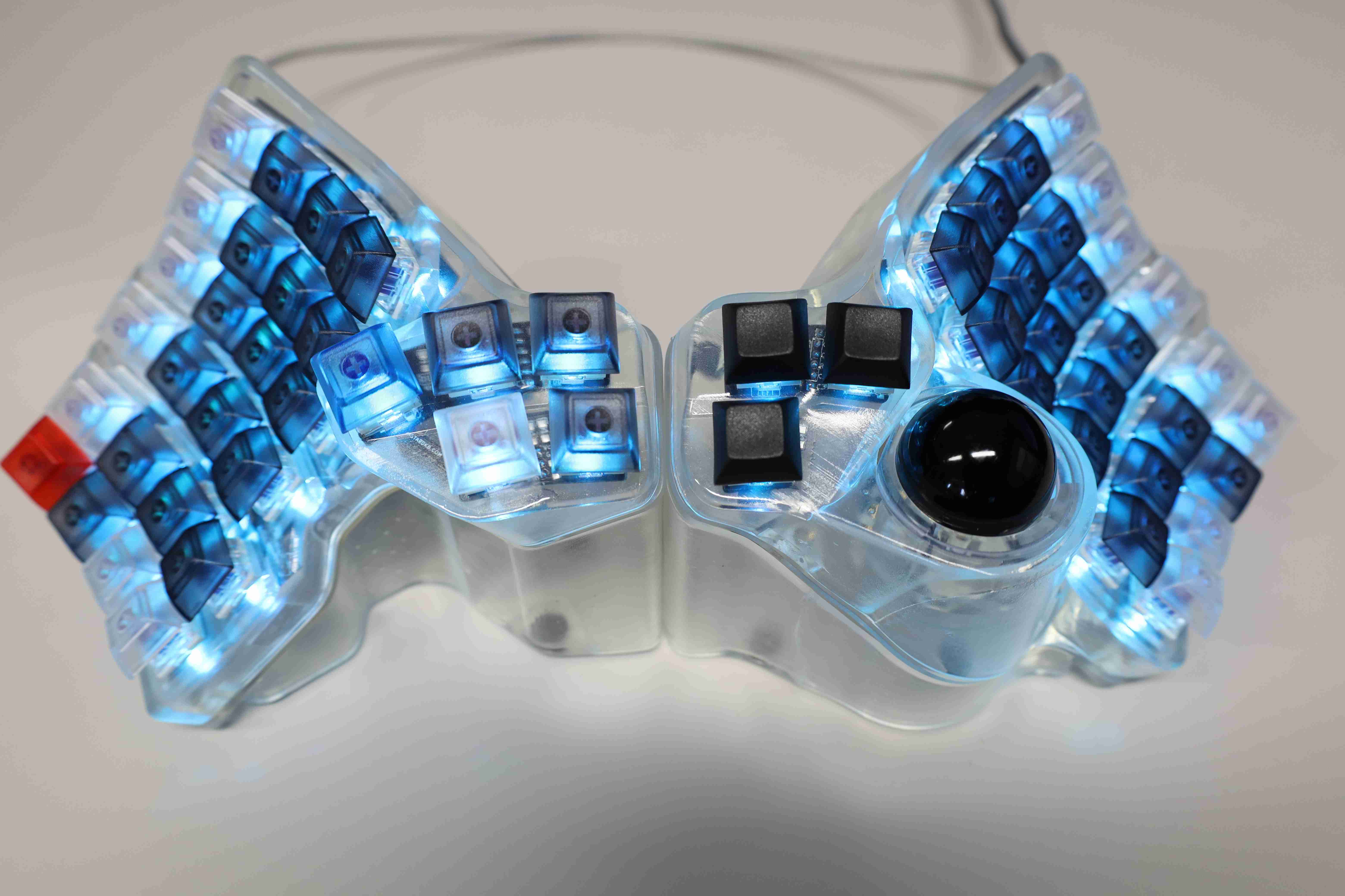
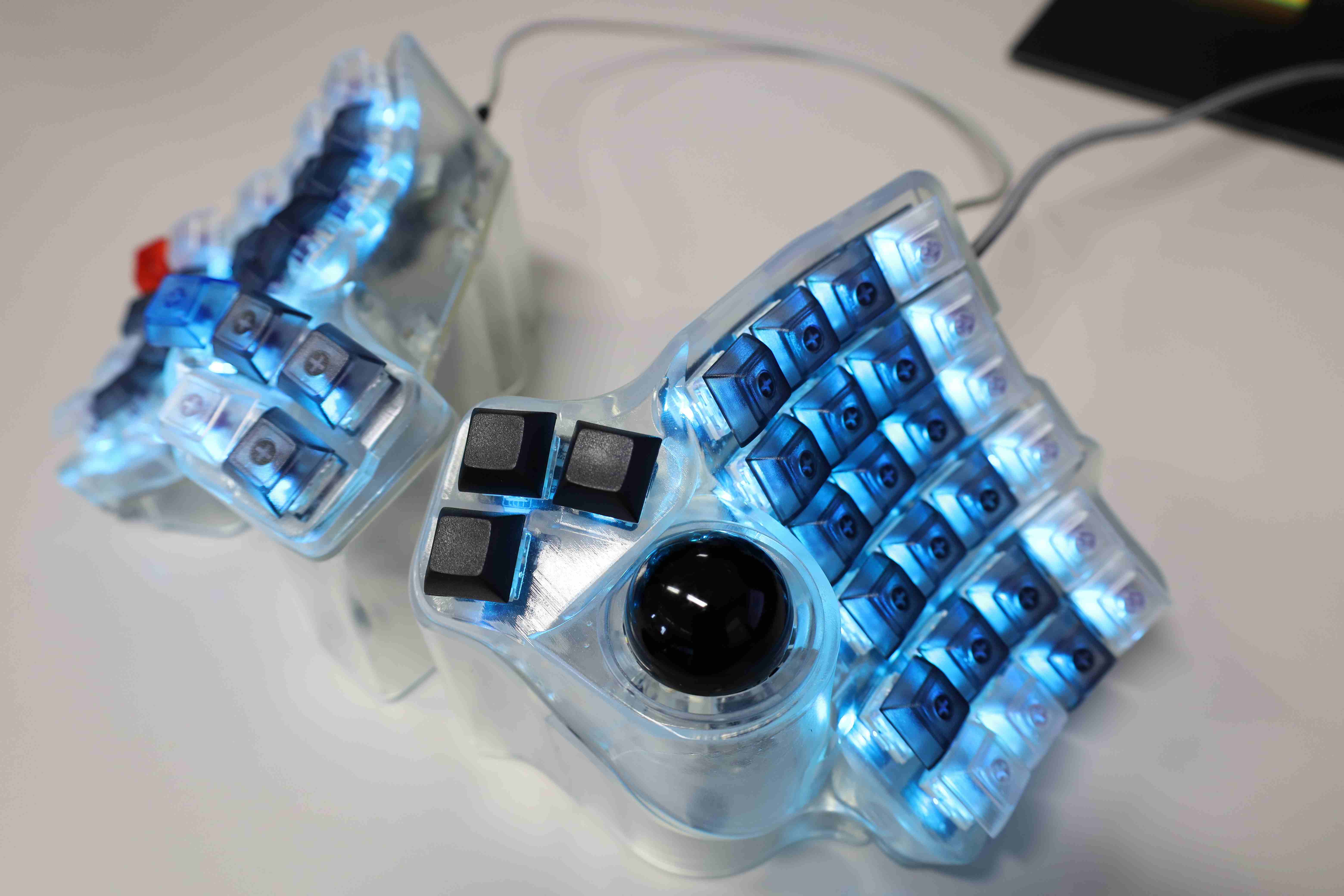
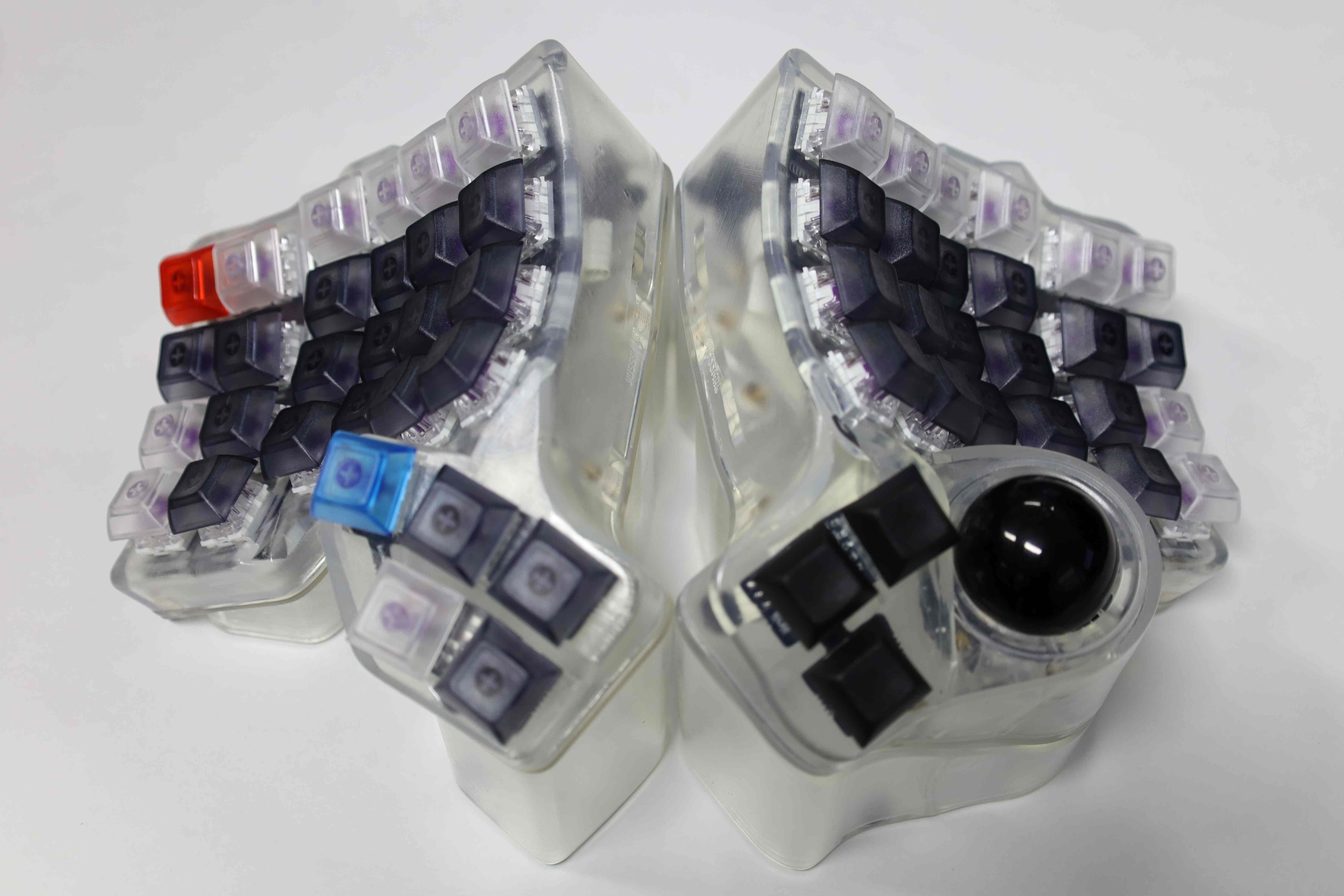
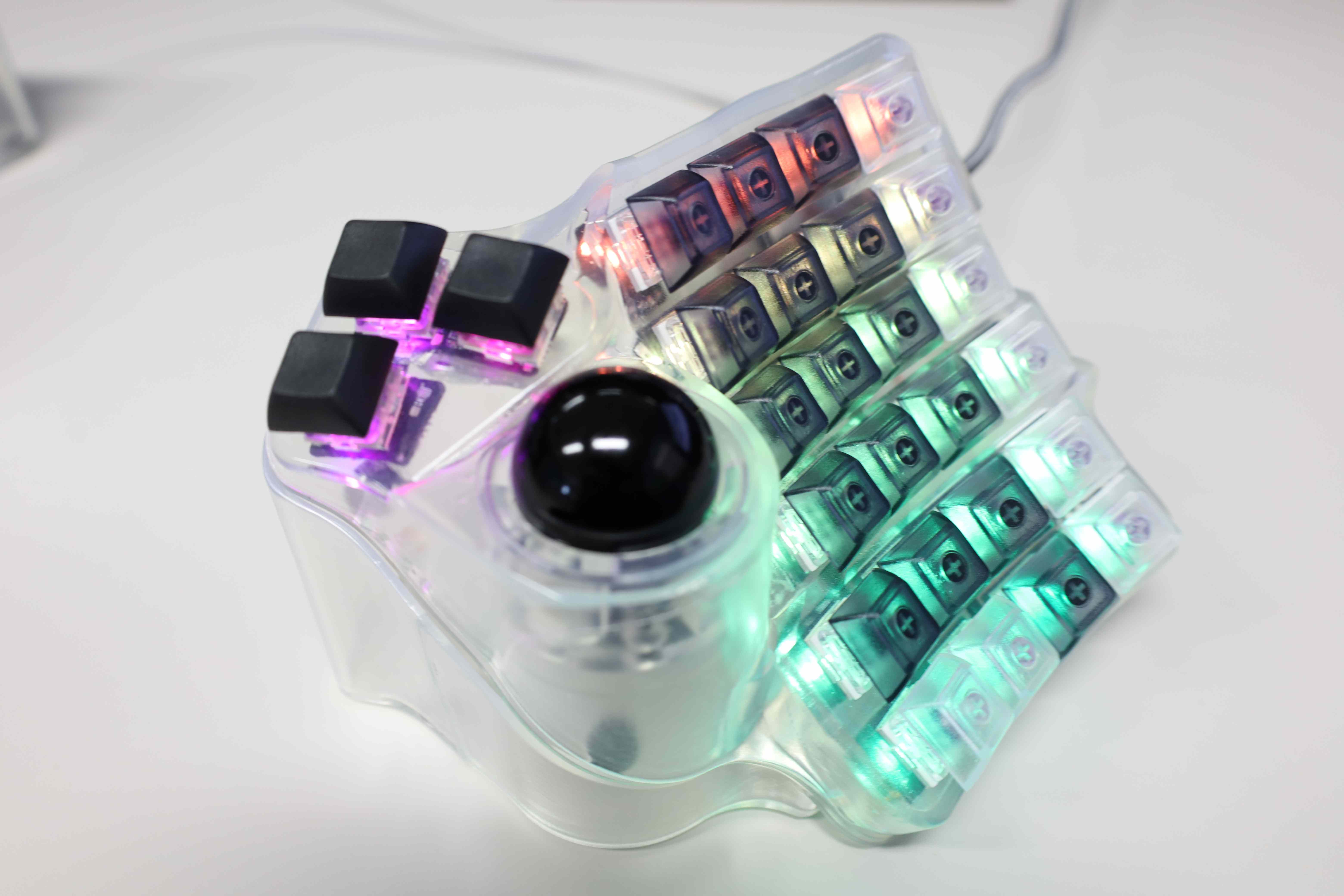

and much more in the build log.
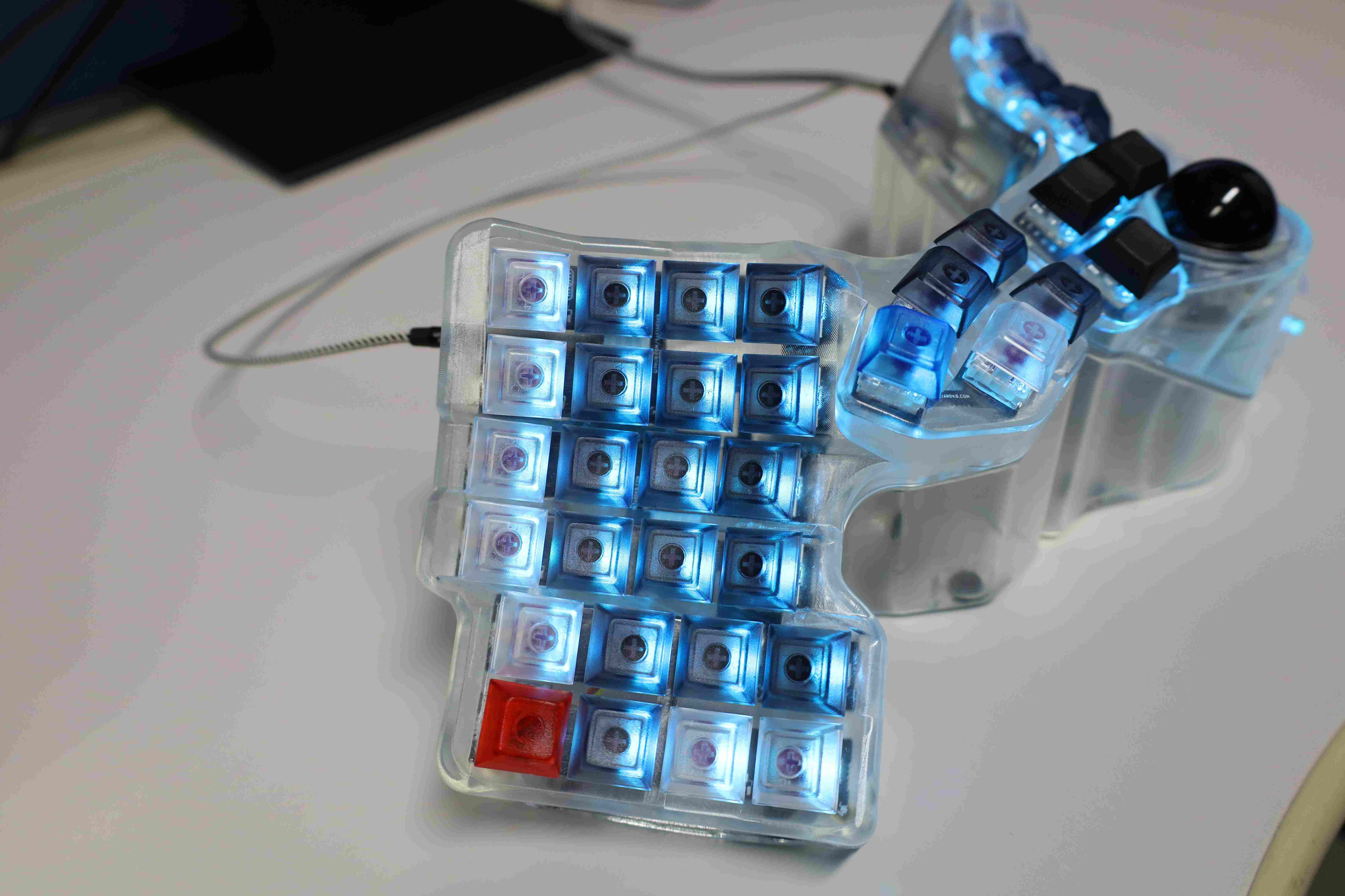
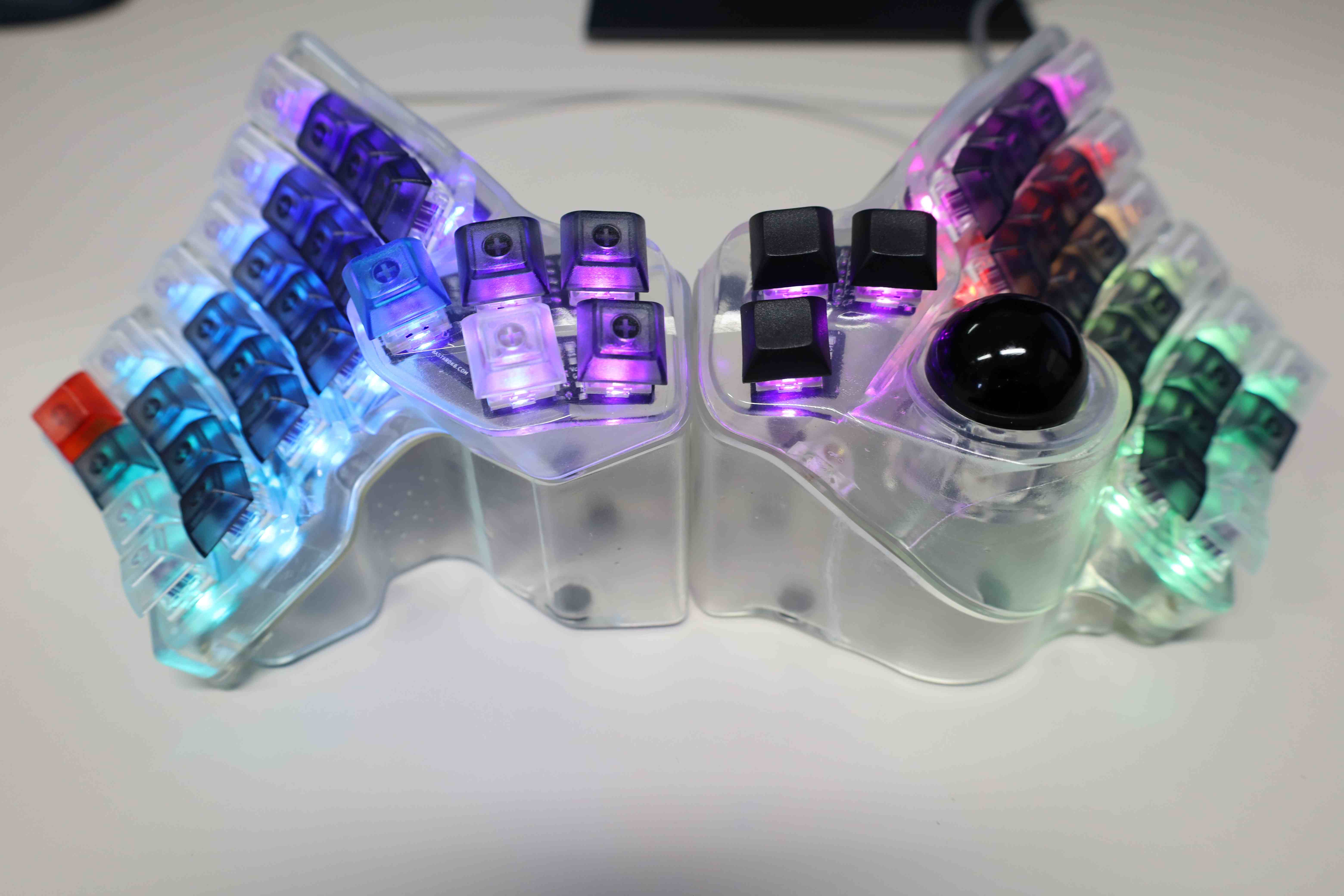
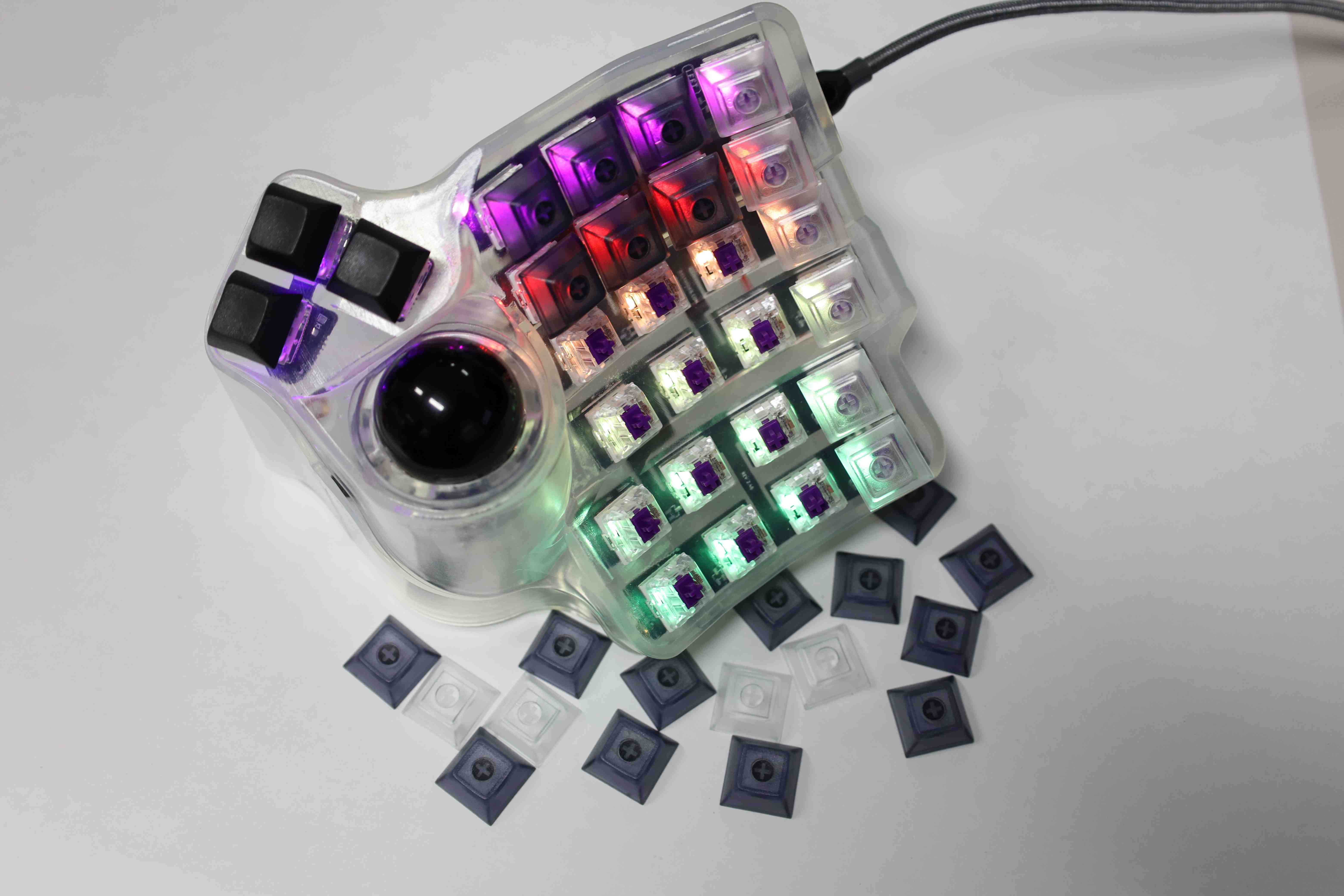
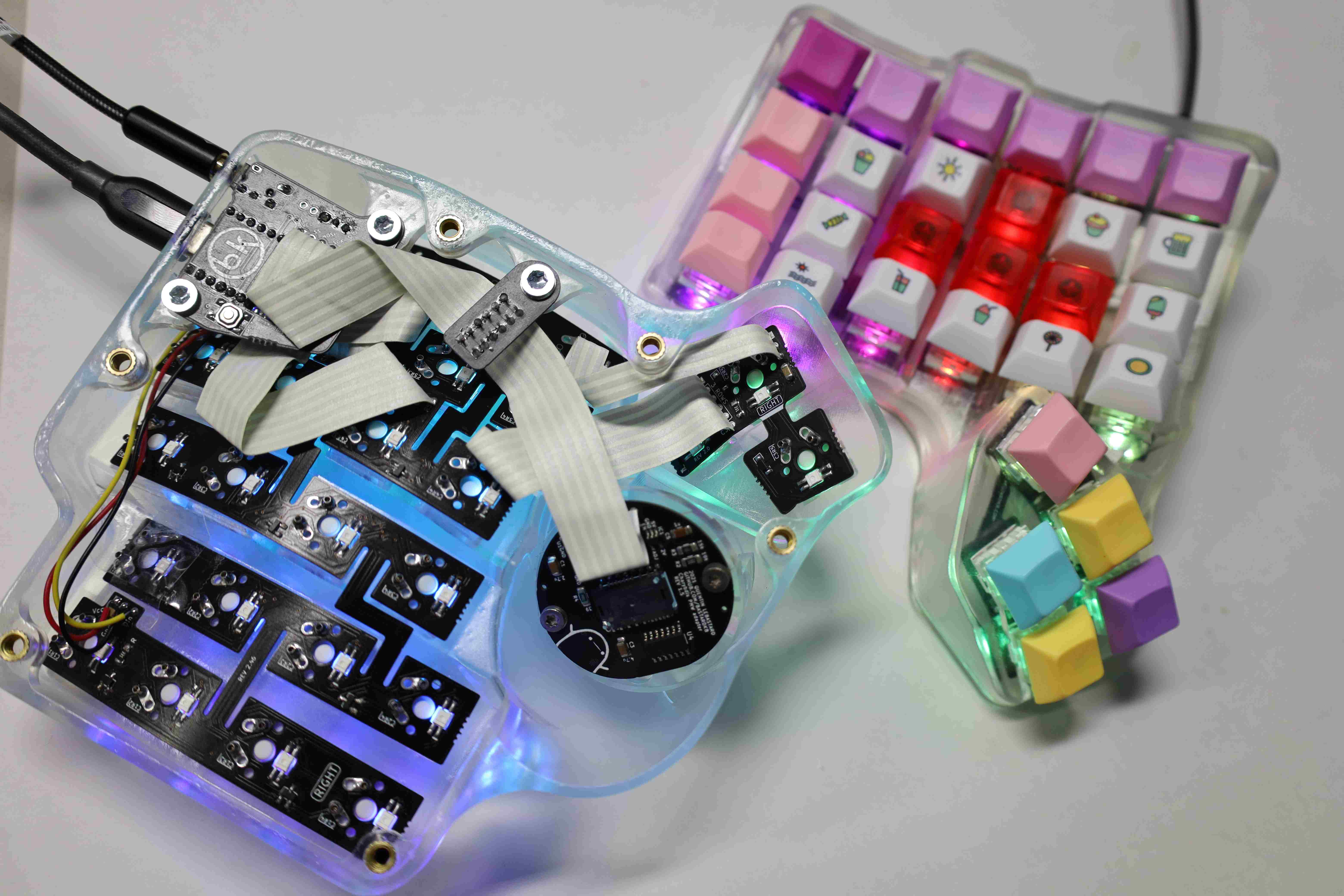
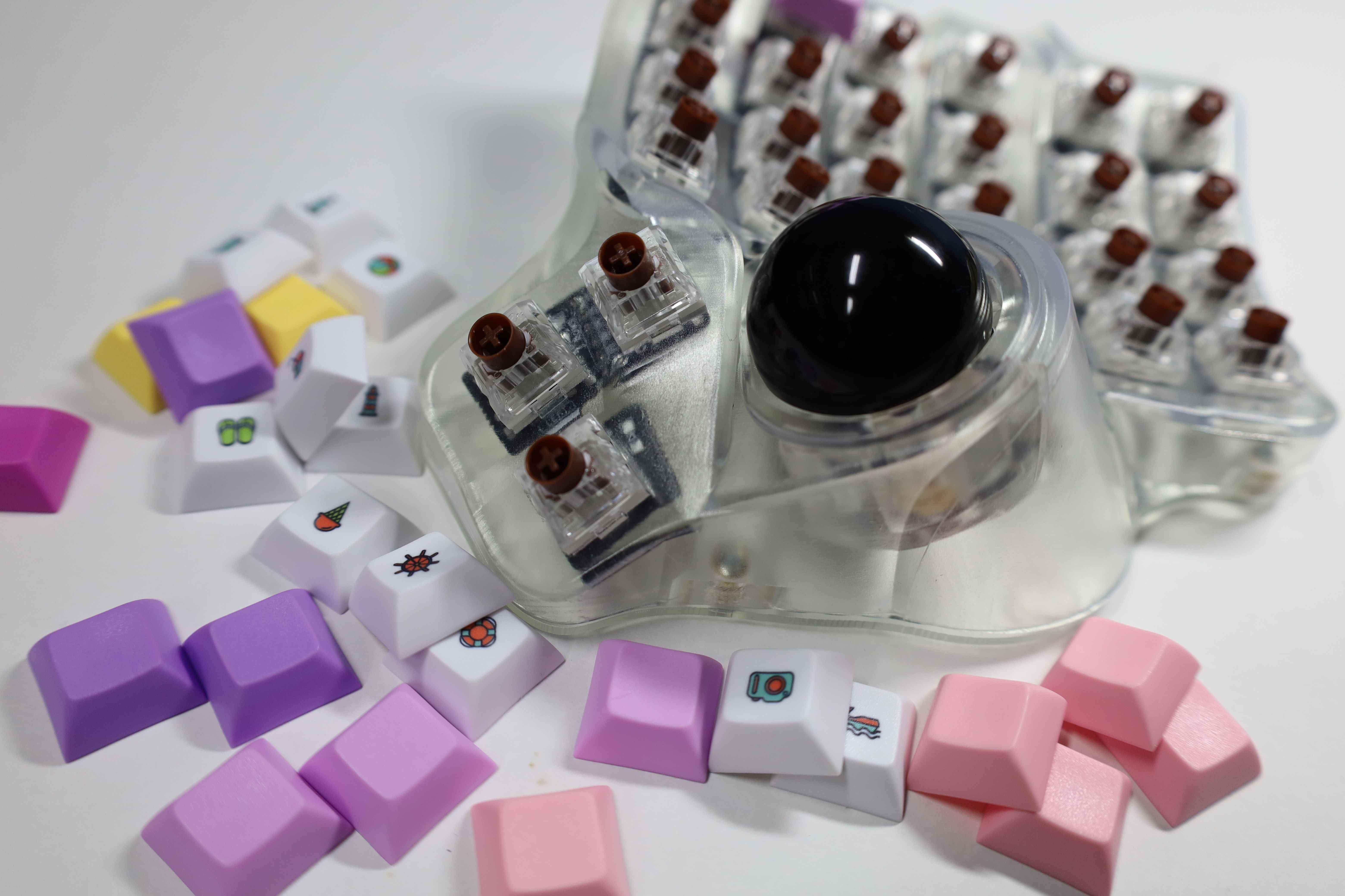
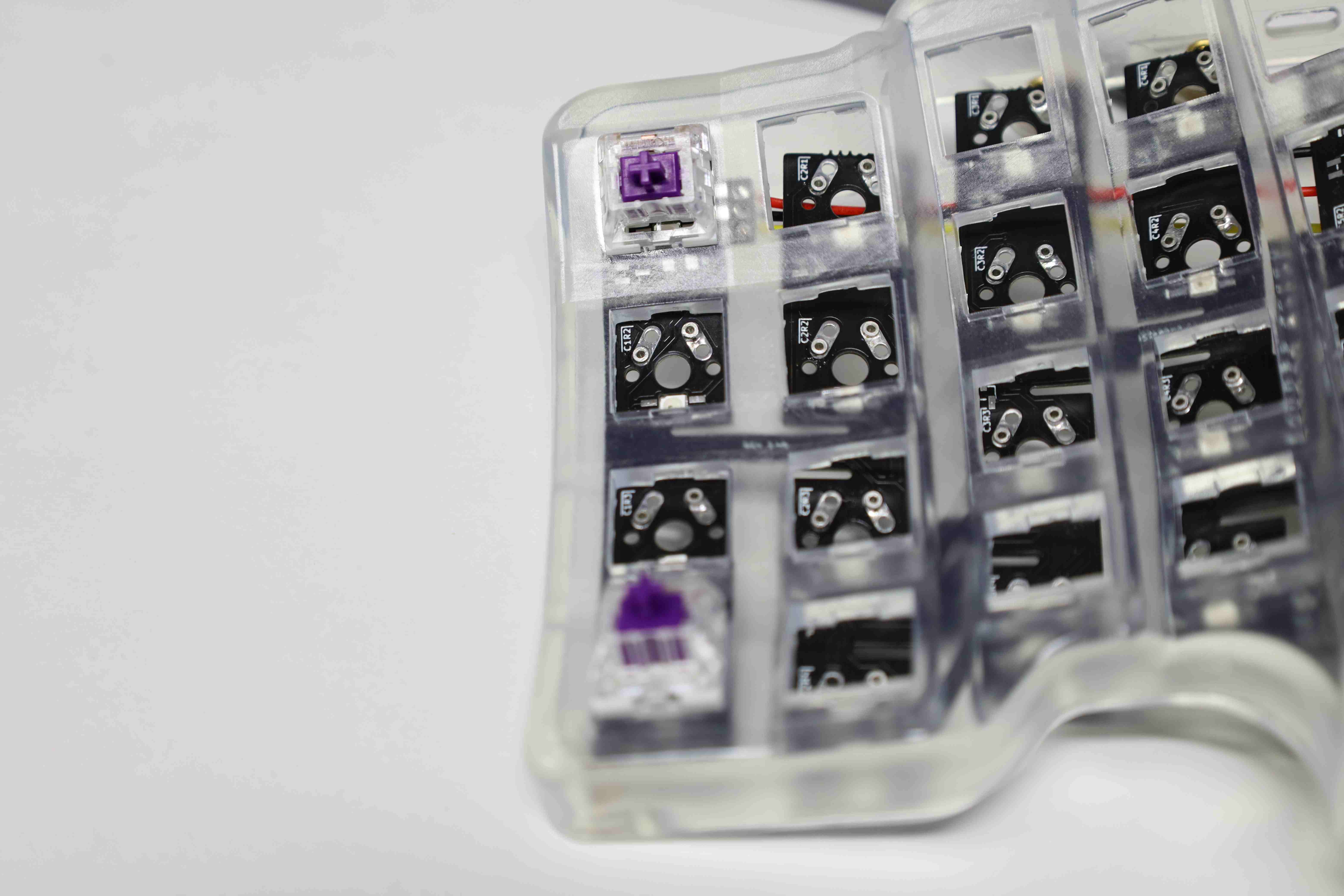
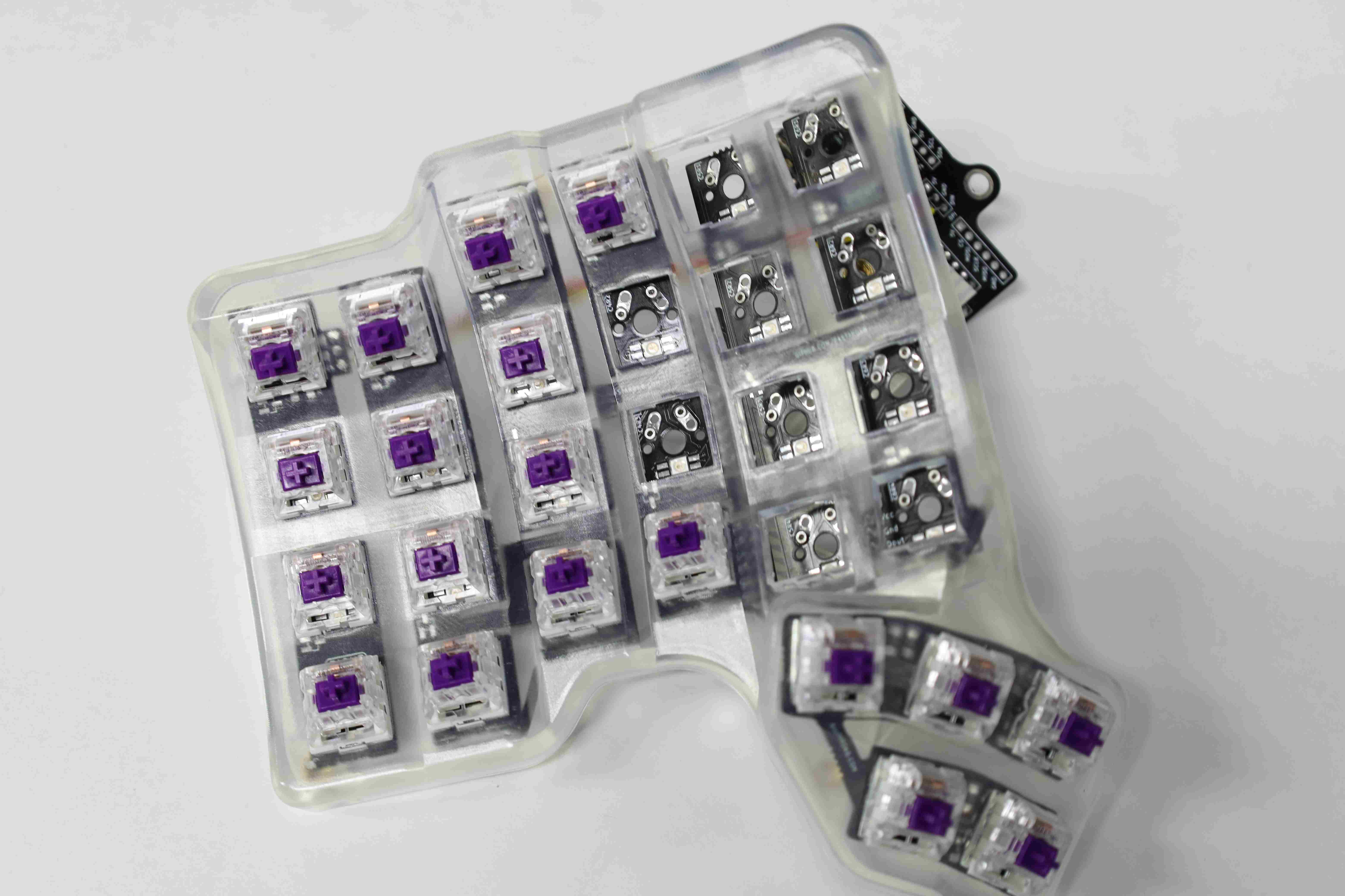
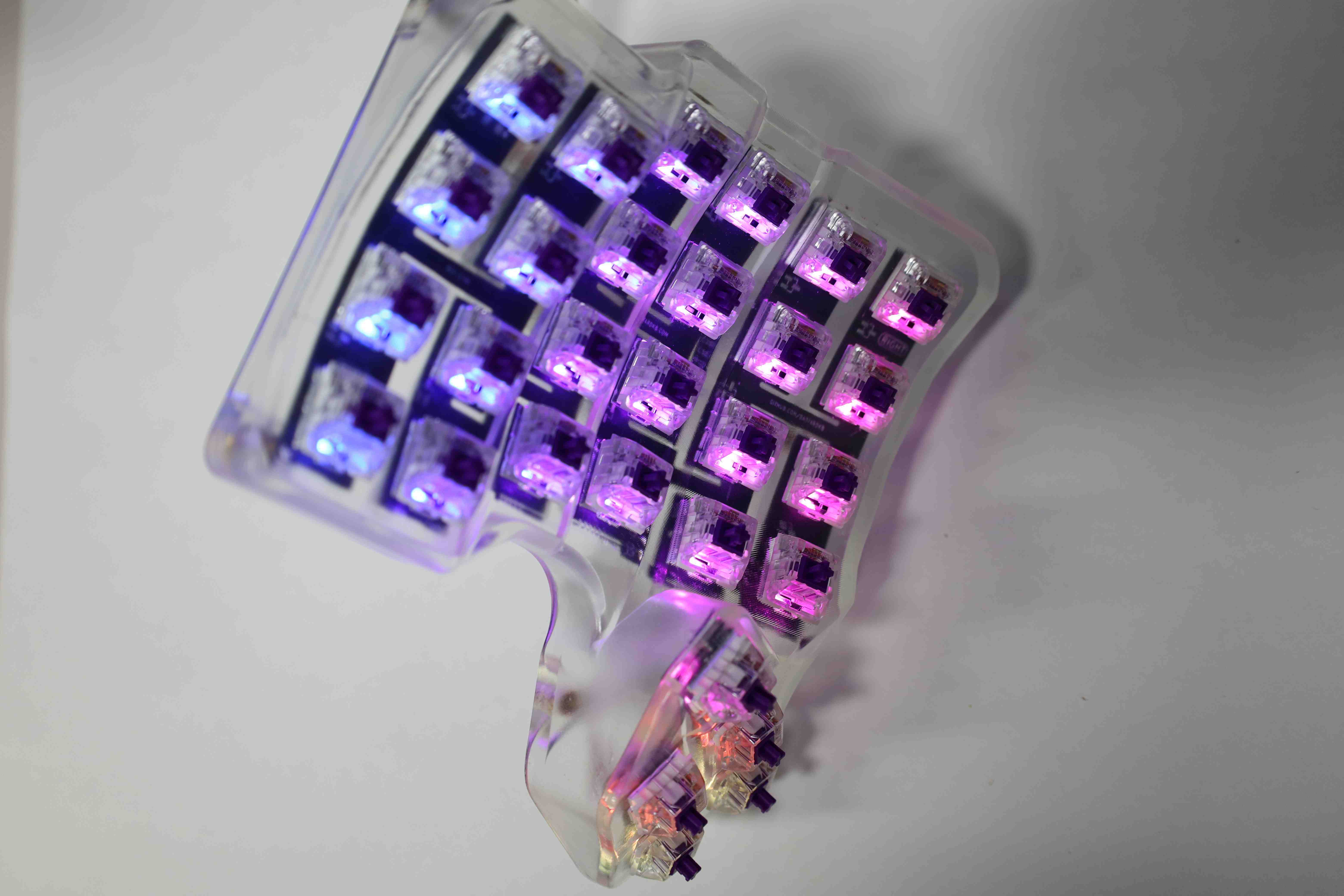
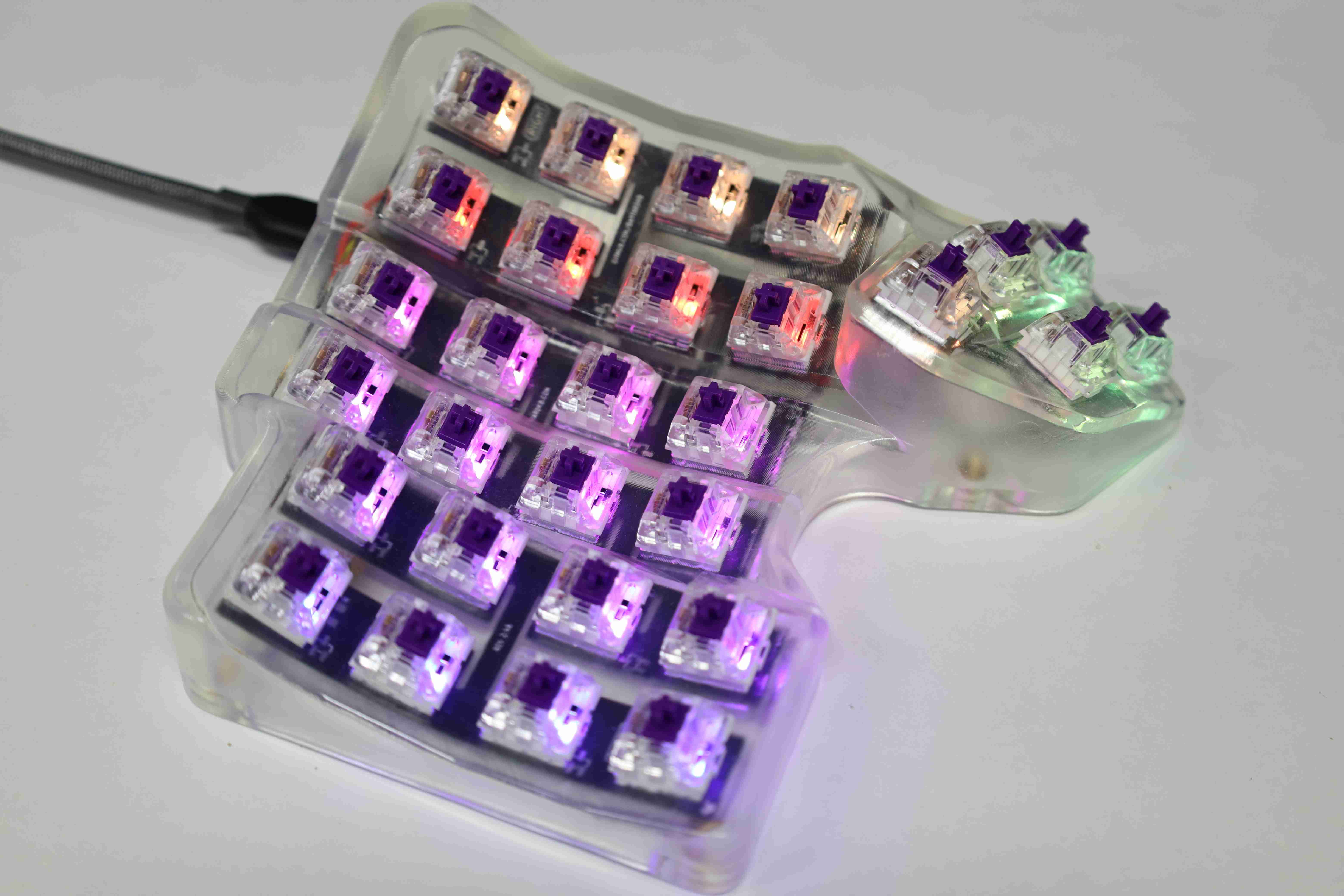
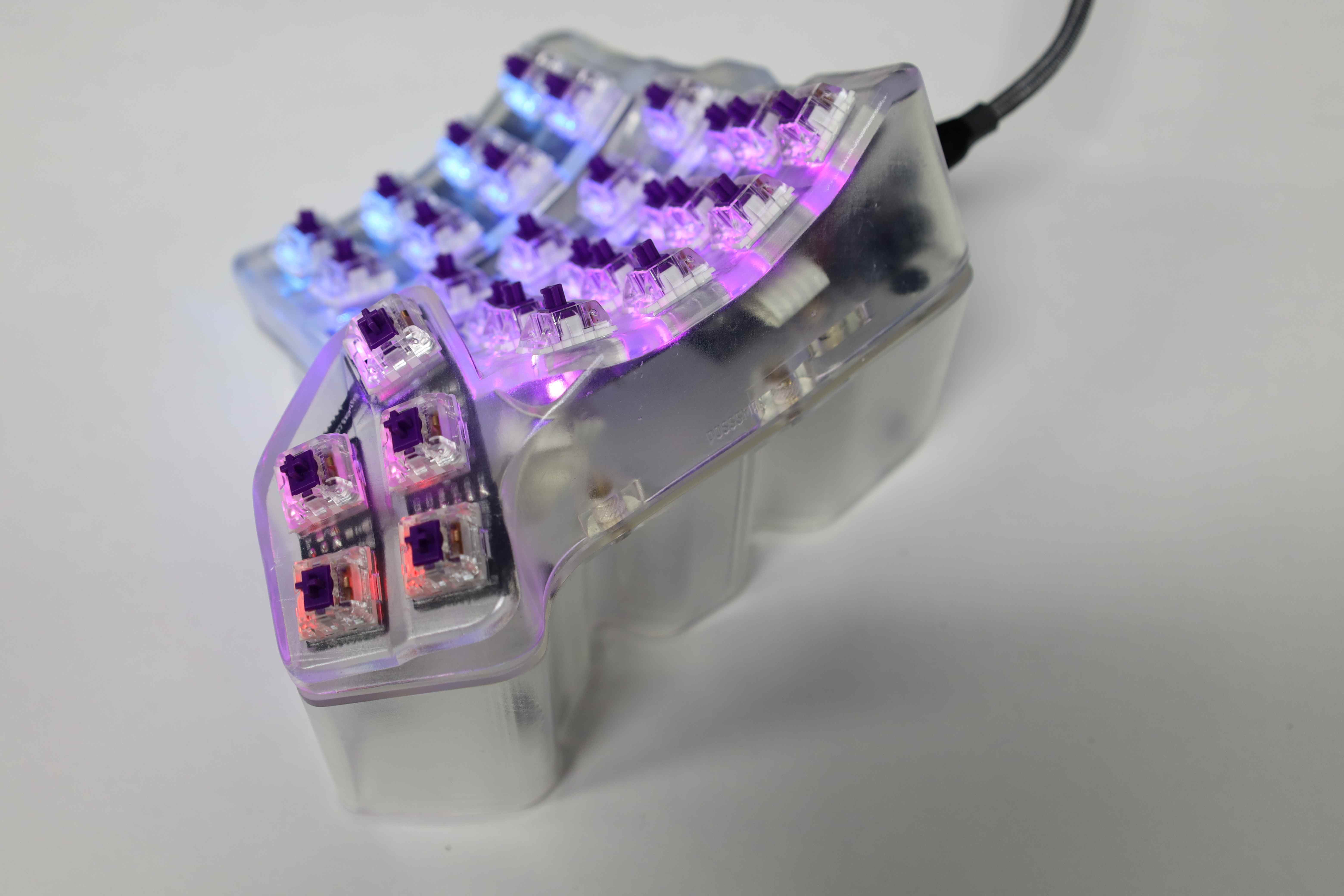
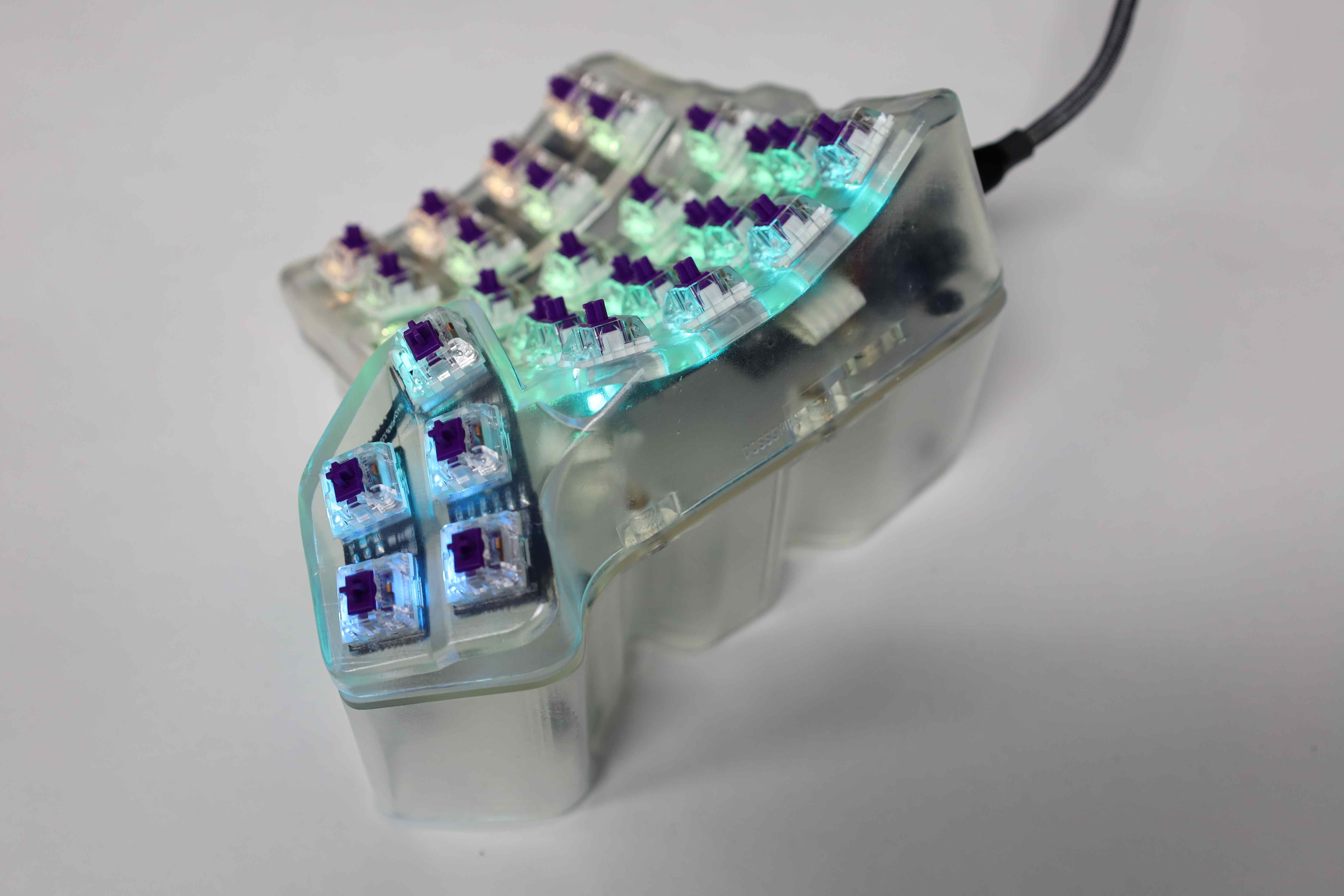
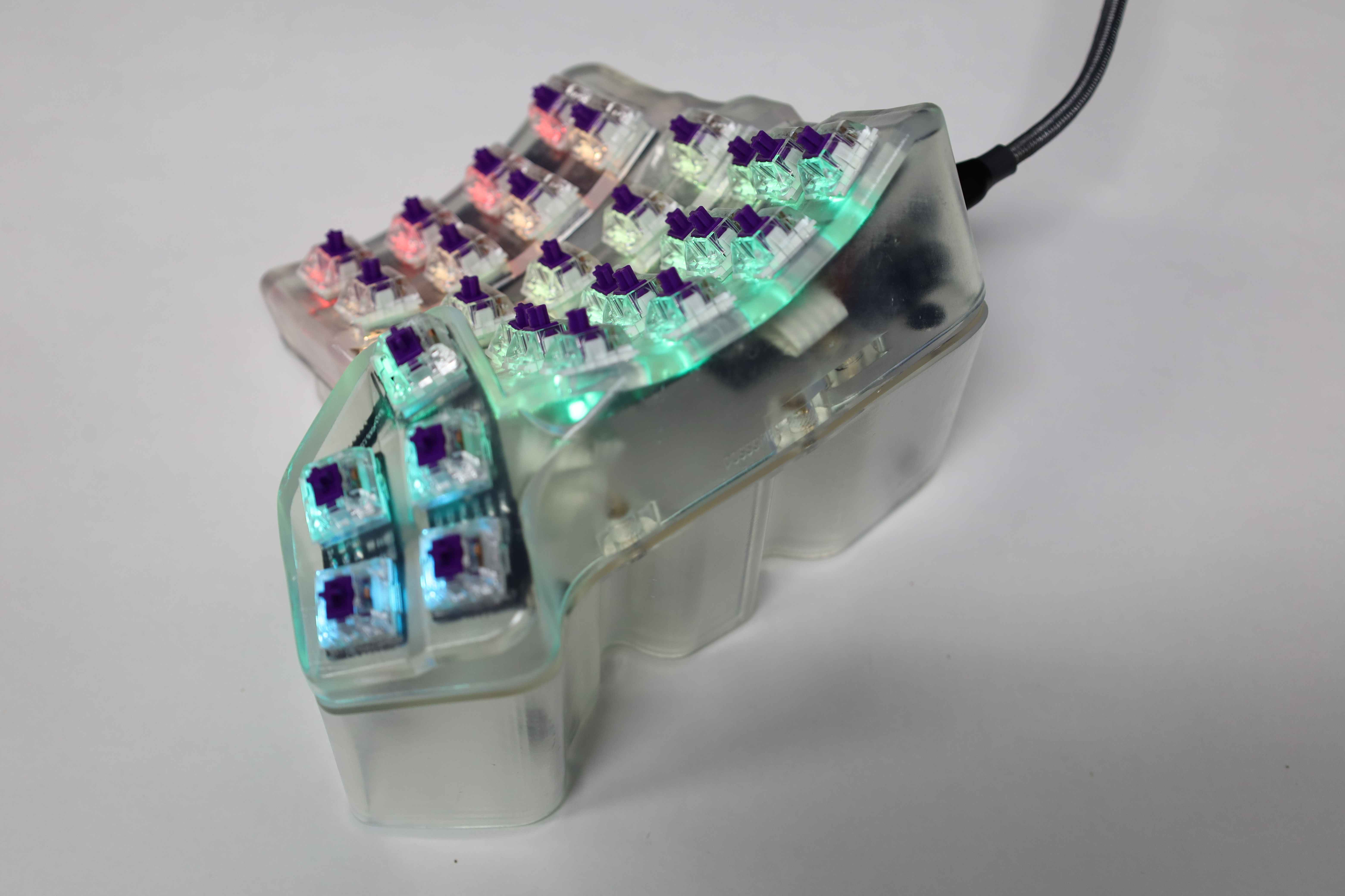
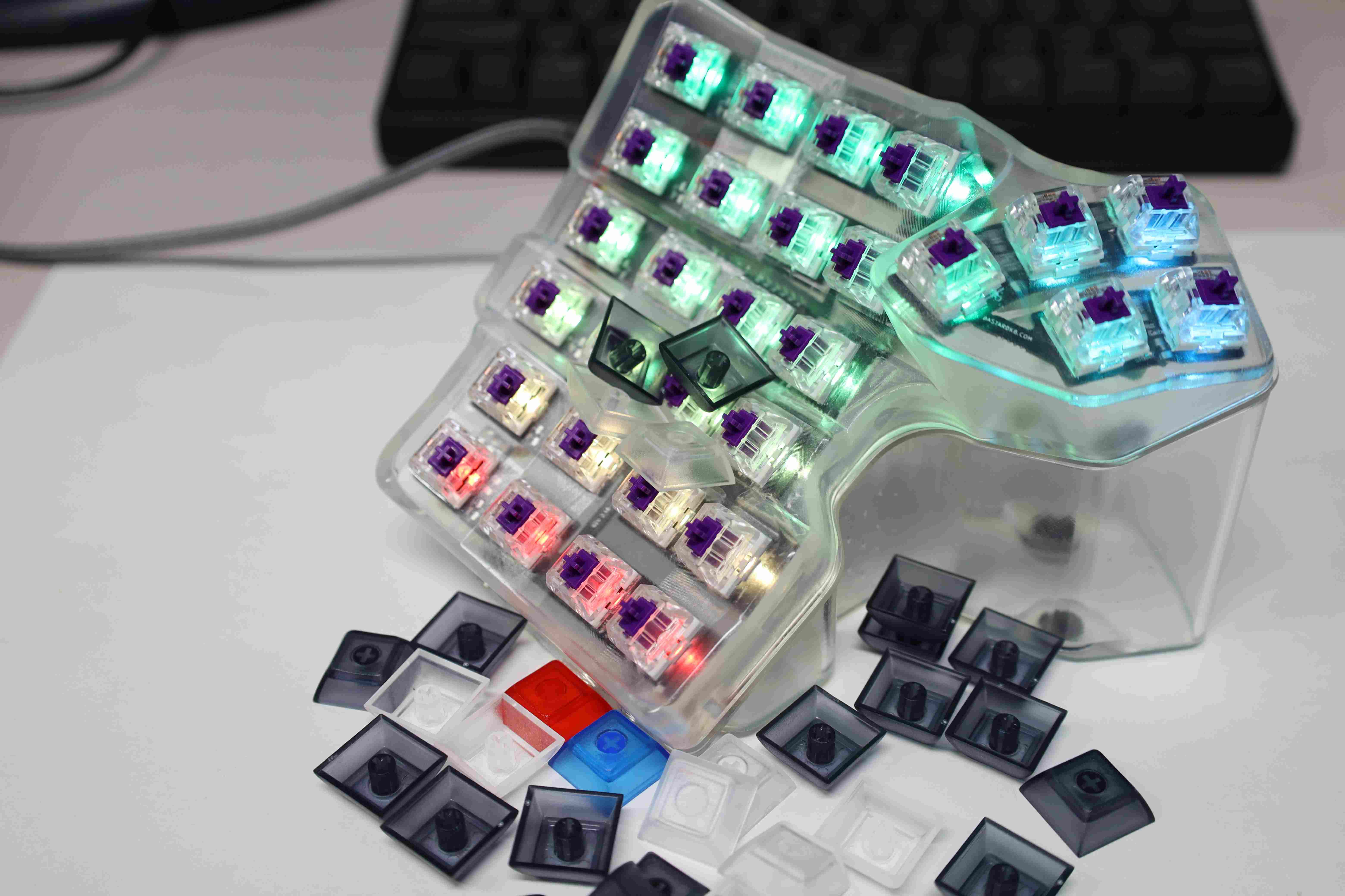
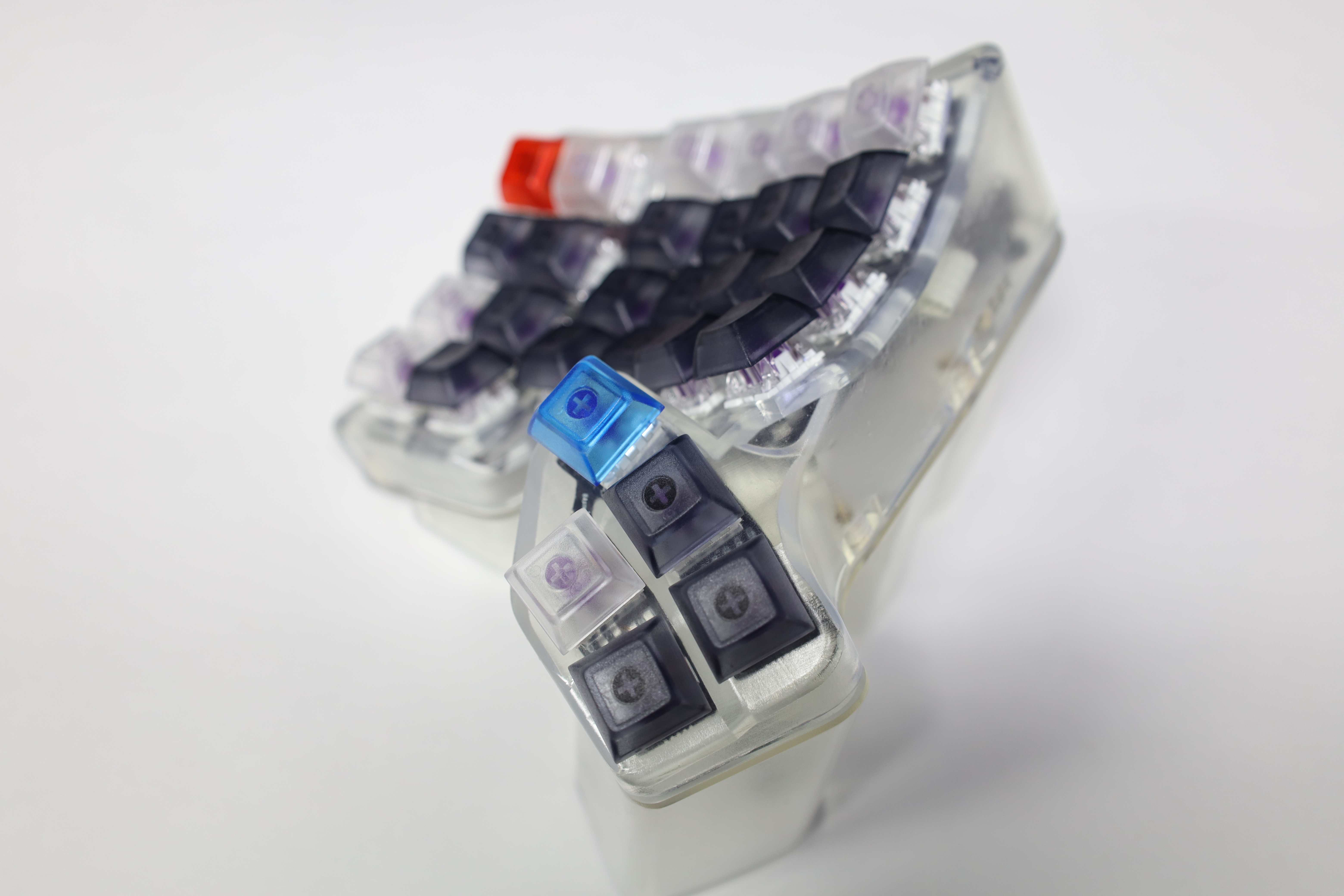
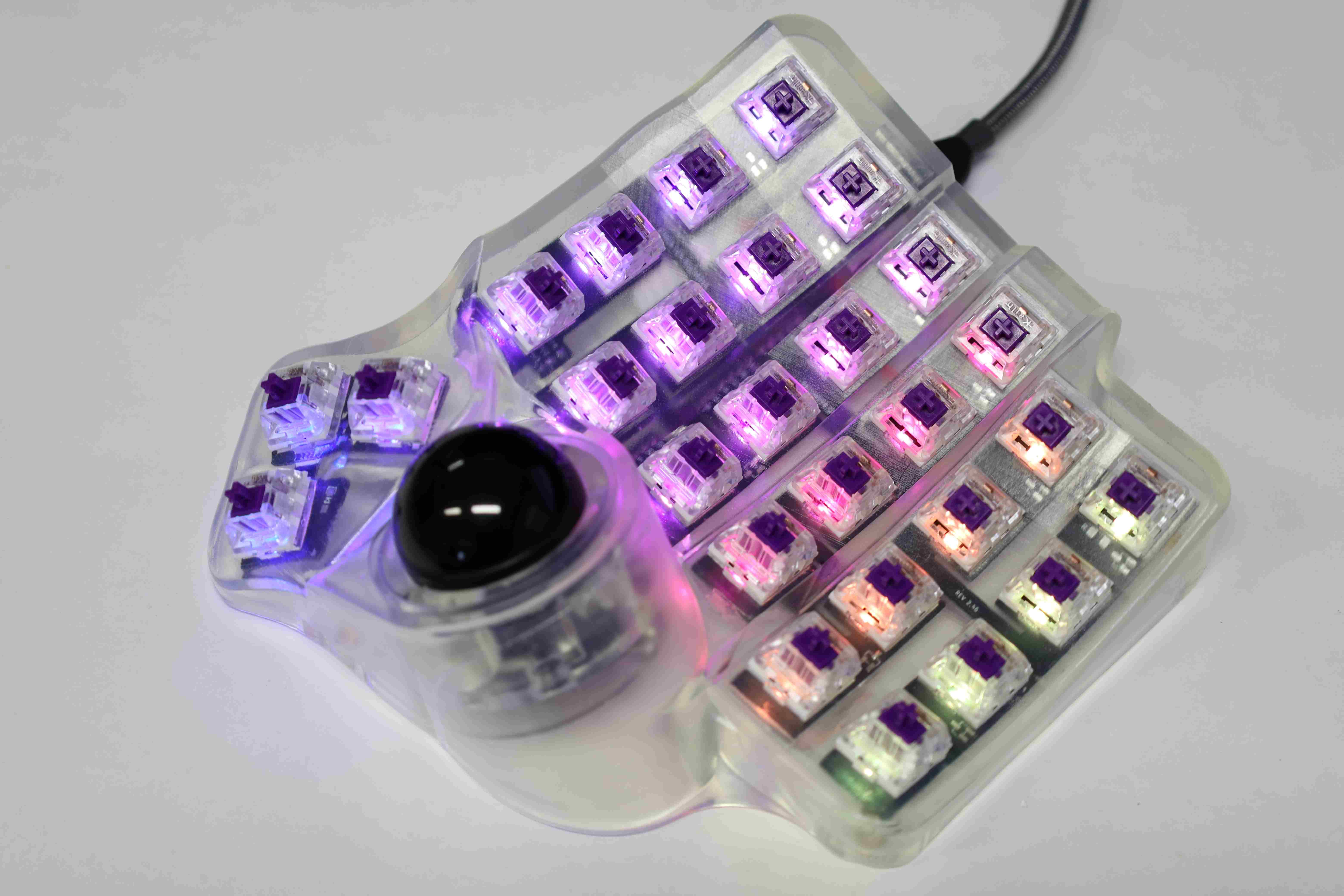
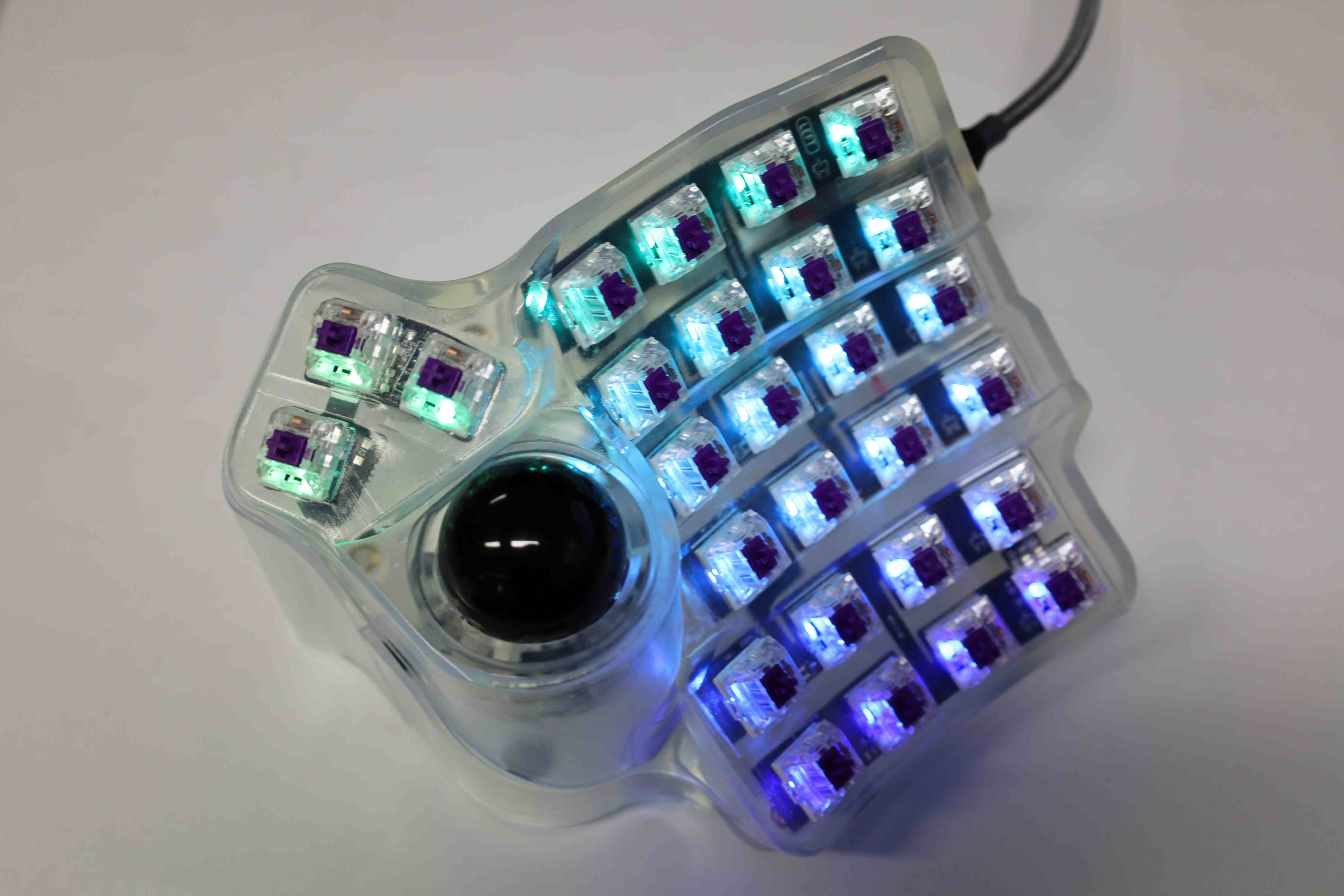
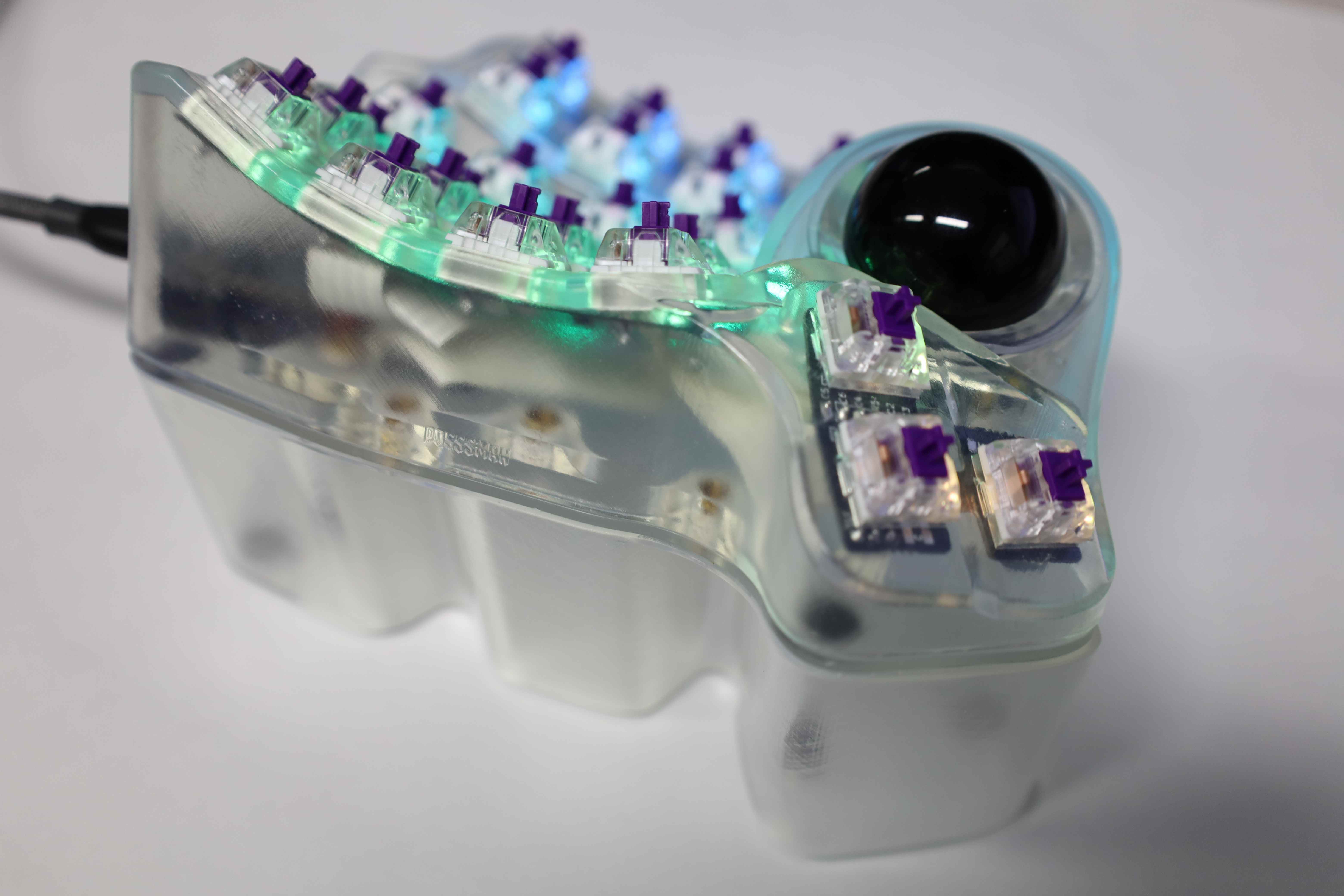
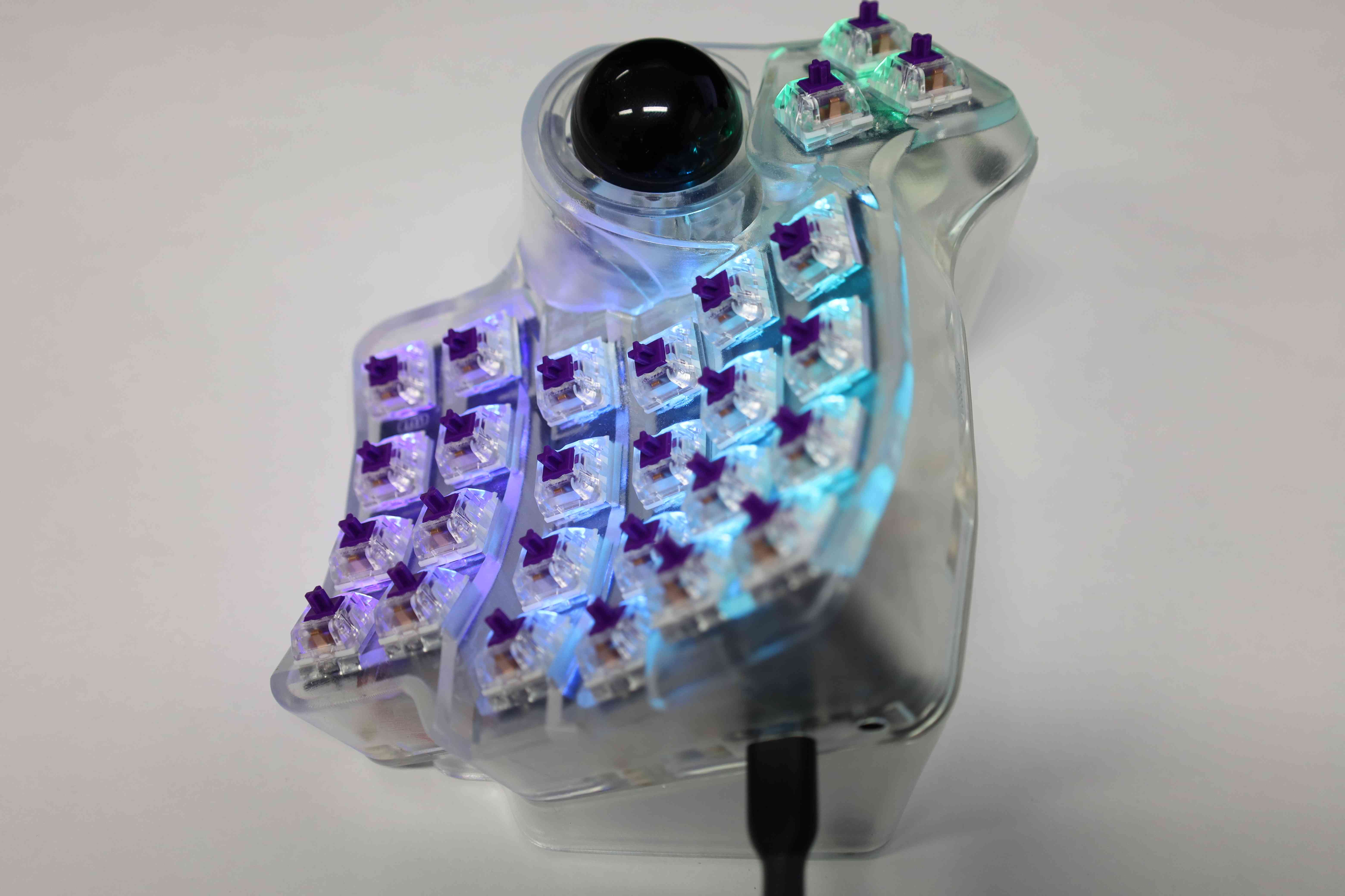
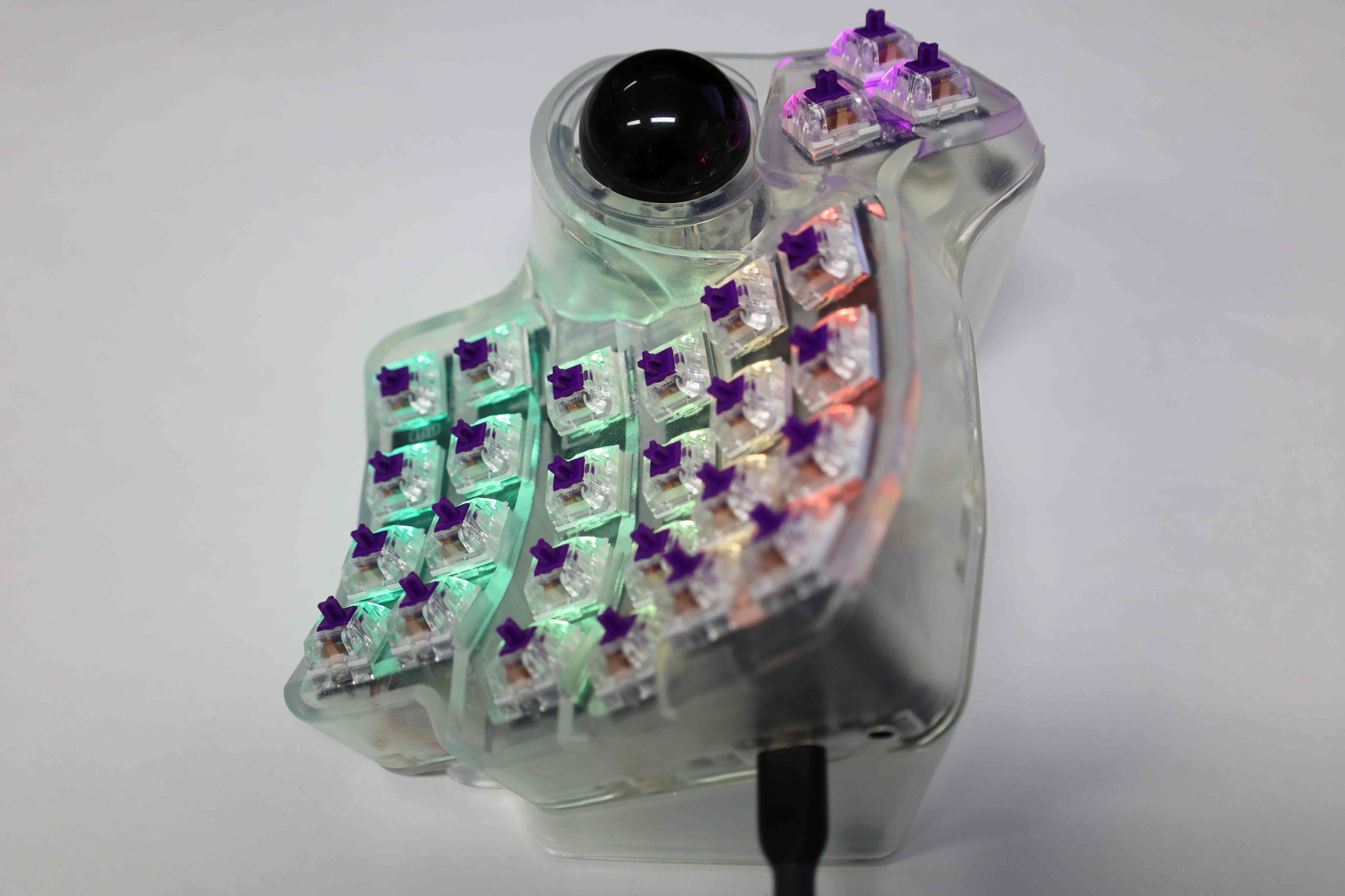
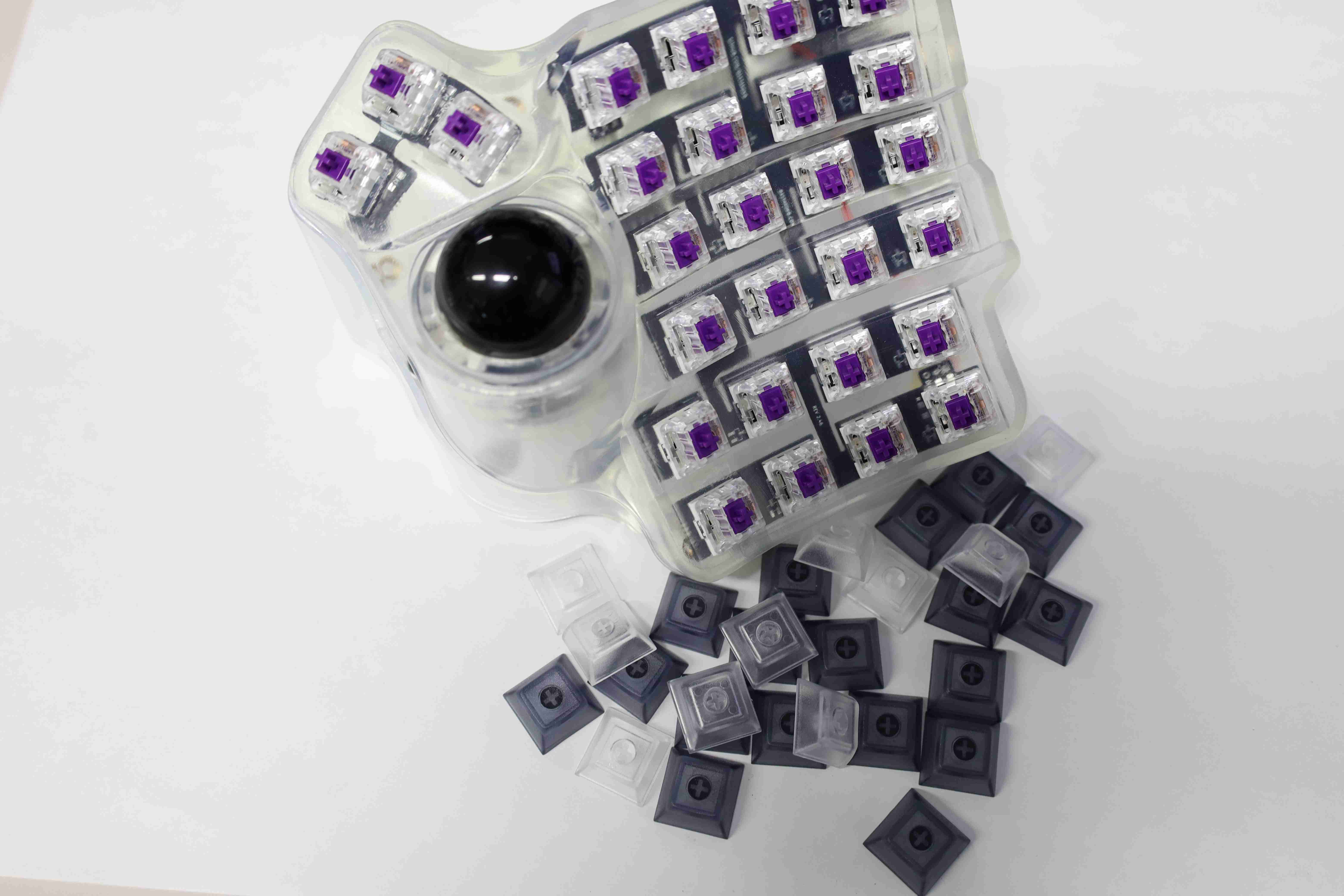
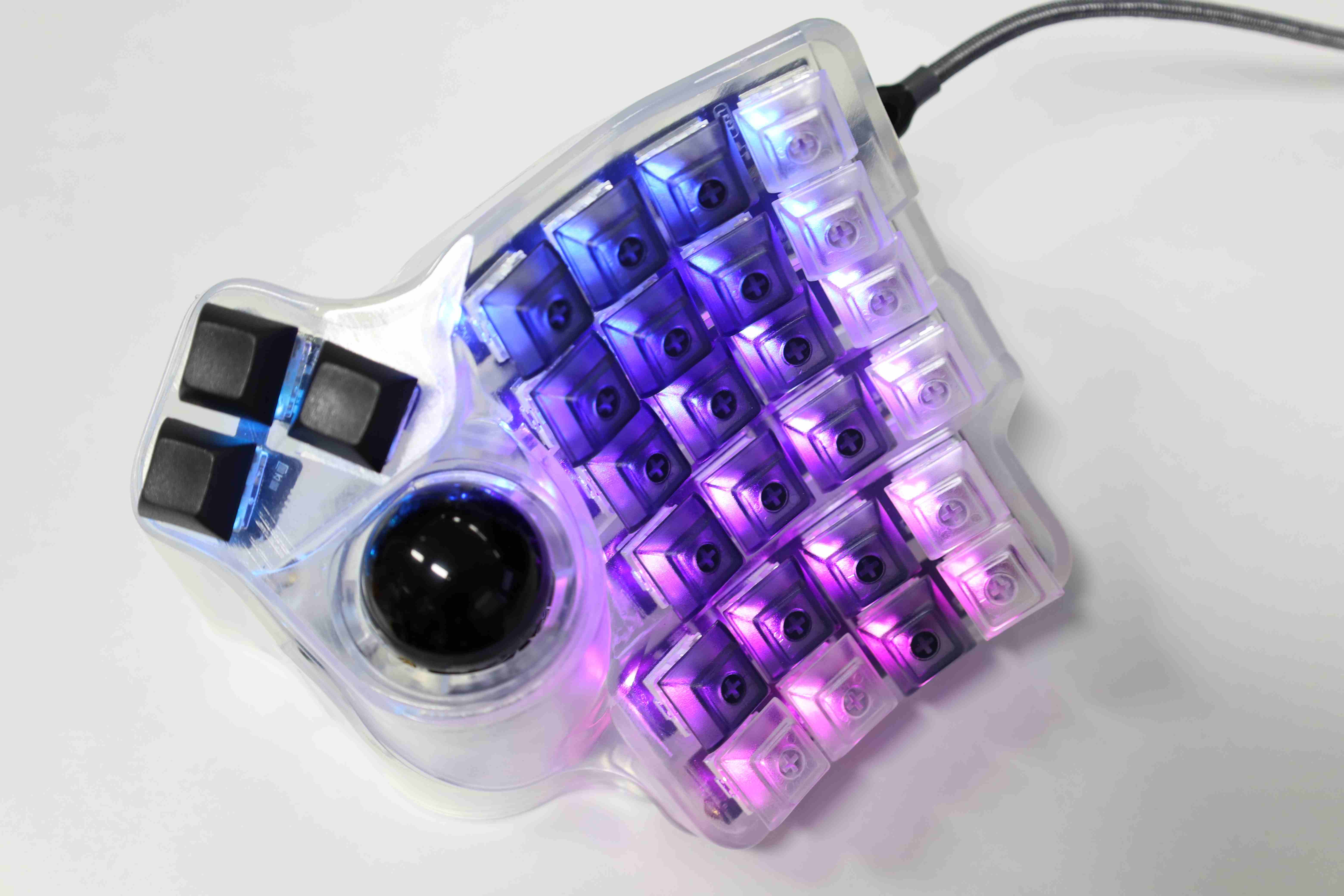
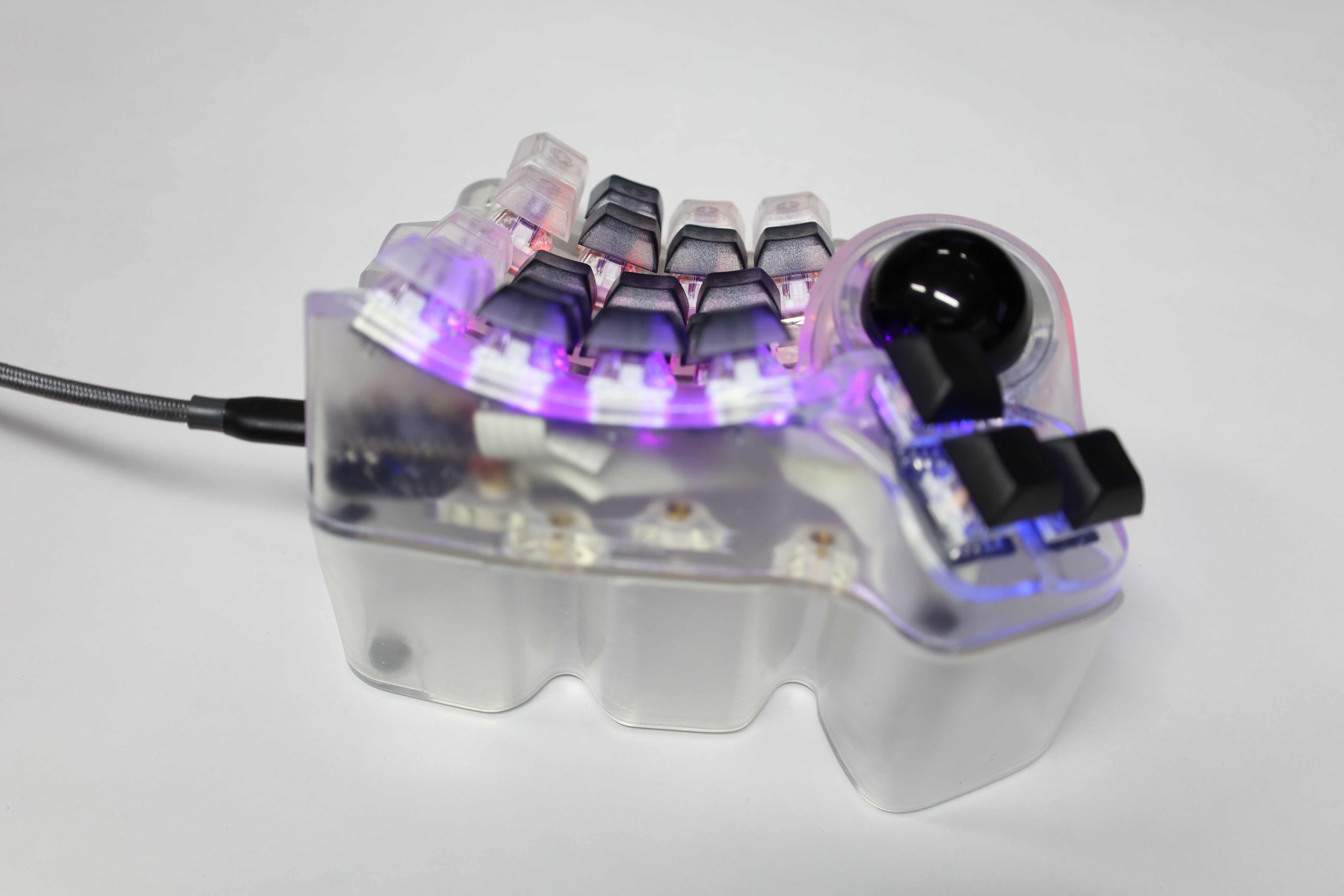
Showcase #2
Note: Unlike the build in the previous showcase, this one uses Kaihl Box Brown switches.


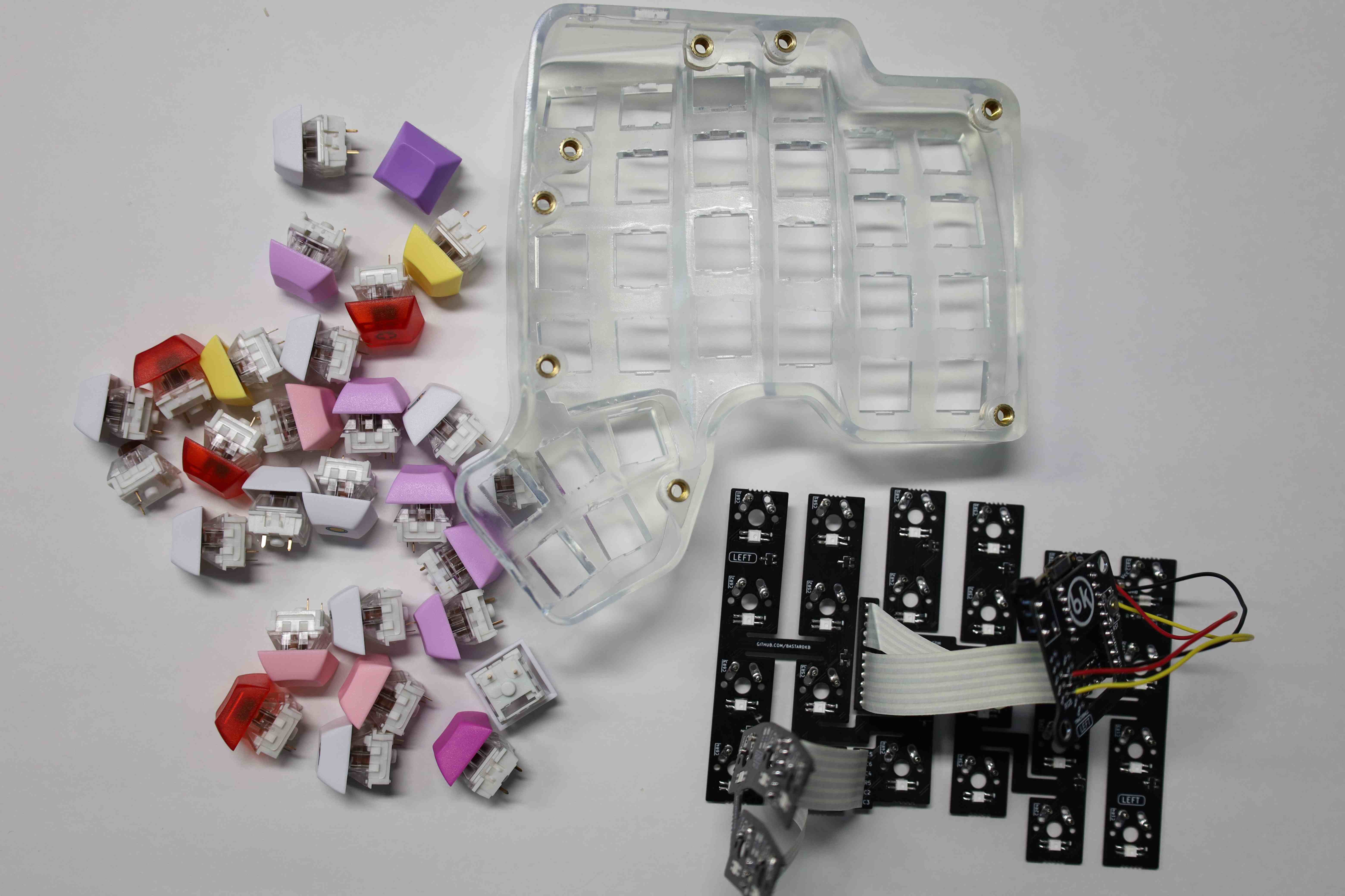


Specifications
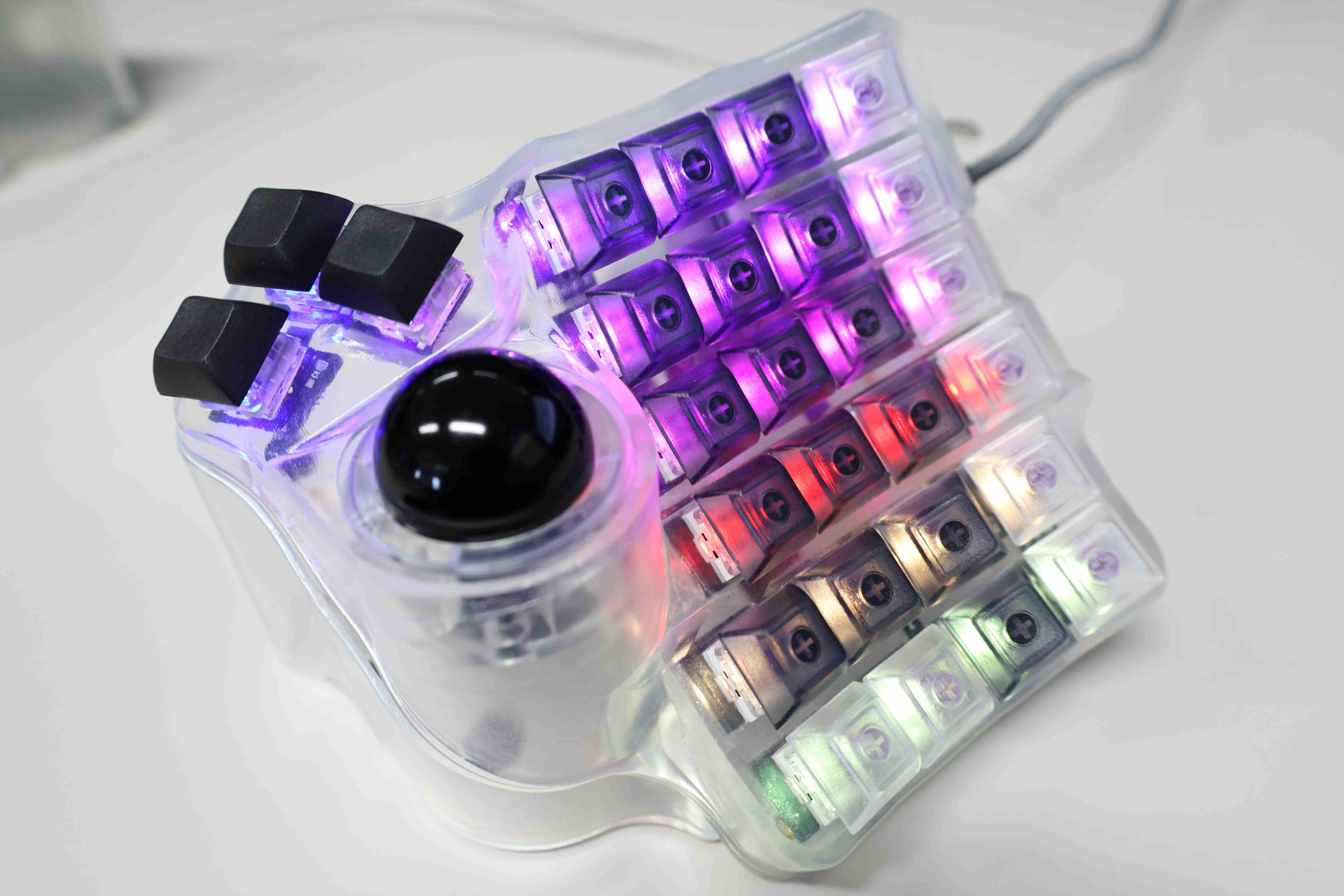
Model: Charybdis 4x6
Case:: 3D printed with Formlabs 3, Clear Resin v4, and custom embossed STL files Left Right
Switches:: Kaihl Pro Purple x 56
Keycaps: Blank translucent DSA keycaps mix
Other:
- Clear case
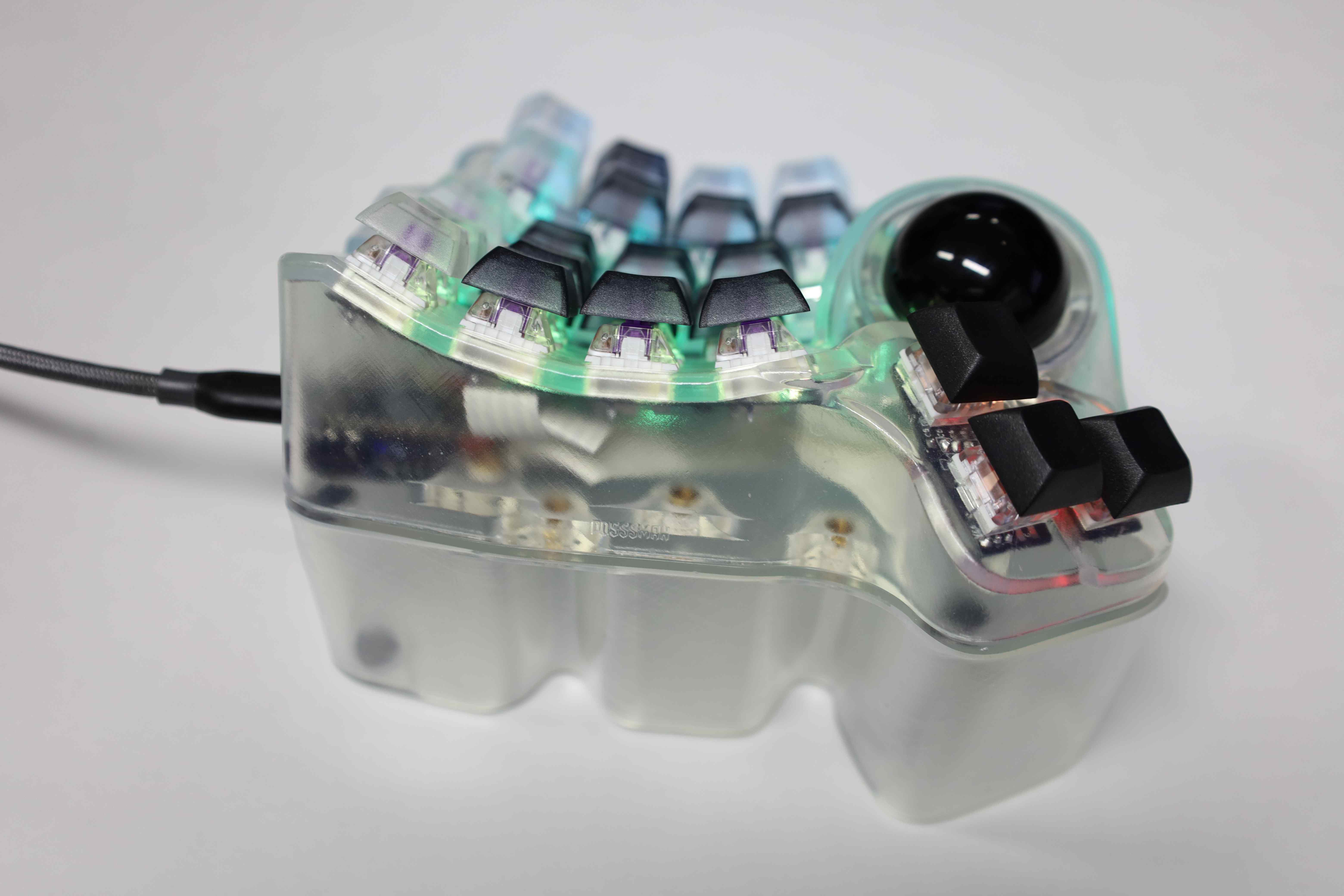
- Trackball with 3D printed BTU instead of the default bearings
- RGB key back-light
- Hot-swappable key switches
- Socketed Elite-C micro-controller (MCU)
Benefits
- Departing from the traditional staggered key layout toward columnar or staggered ortholinear (such as ErgoDash too) is a net positive. Charybdis brings this aspect one step further by adding depths to match the different lengths of each finger.
- Split and tented keyboard allow for a healthier and more comfortable posture. Namely, pronation of the forearms is reduced thanks to the tenting that makes the board more vertical. Meanwhile, having a split keyboard lets you keep the back straight, the chest out, and the arms wide and stretched, which should be a more natural position overall. More intuitive explanation on the benefits here.
- The thumb, criminally underused on traditional keyboards are empowered with thumb key clusters, increasing typing efficiency.
- Frees up some real estate on the desk, and makes it more flexible.
- Freedom to customize the keyboard layout to fit one’s specific needs, which can bring non-negligible quality of life improvements.
- Compared to the previous ErgoDash build, Charybdis’ trackball combined with an even more reduced key count and the leverage of layers drastically reduces hand movement, thus further improving comfort and efficiency while sporting a compact form factor.
- [Build specific] Hot-swappable switches makes it easy to change a broken switch later without having to pull out the soldering iron. On this build, however, the top and bottom rows’ switches will likely require unscrewing the bottom plate of the case to hold the flexible PCB while swapping the switches.
- [Build specific] Socketed Elite-C micro-controller further increase the modularity of this build. This essentially removes the worries about having the Elite-C properly aligned with the case when soldering it to the PCB shield. More importantly, it will allow for a quicker and relatively painless replacement or fix when needs be (For example, the USB port on the micro-controller side can break due after a few thousand plug-in plug-outs. This happened with the previous build, albeit with a weaker, Pro Micro controller).
Caveats
- Pricey. With a base price of around 400\$ (probably), it can go higher depending on the kind of components one decides to use. This specific build amount to 720\$, and that is without accounting for the 3D printing machine used to print the case, and the soldering tools.
- Requires some technical skill (electronics assembly and soldering, diagnosing assembly problems, etc…). Compared to the ErgoDash, the Charybdis has a higher difficulty namely due to the presence of a trackball and flexible PCB mounting (especially if doing a hot-swap key switch build).
- For someone that has gotten used to standard staggered keyboard layouts, there will be some learning curve for the new layout. This barely passes as a caveat, as the comfort of using an ergonomic keyboard vastly makes up for it in the medium to long term.
- Once you try it, you will never want to come back. In case one has to work at different physical locations, the high price and time investment makes having duplicate configuration prohibitive. While proficiency with standard keyboards will hardly be affected, it becomes very unpleasant to use them. In my case, having to use a standard case leads to unending rants and bouts of annoying ergo keyboard master race elitism that probably annoys the people around. Using laptop keyboards also becomes a similarly unpleasant (and potentially painful) activity.
Highlights of the building experience
- When 3D printing your case, make sure of the orientation of each case and the corresponding tenting and bottom plate.
- To maximize the aesthetic of the clear case, the 3D printing supports are better set manually to optimize the polishing process. Automatically generated support will try to satisfy the algorithm that checks the support structure of the print, which I suspect is set to a very conservative standard by the company, to avoid liability in case of failure to print.
- When doing a build with Mill-Max sockets for hot-swappable key switches, the PCB might not hold on tight enough to the case, which can result in some keys not working after the build. So a workaround is to either use some (gorilla) tape or hot glue to fix the PCB to the case.
Build notes (Long version)
Motivation
Around two years ago, I entered the world of custom ergonomic keyboards with the ErgoDash build. While this was a decently balanced build in terms of difficulty and features, there were mainly two shortcomings that kept on nagging over the years, slowly building the impetus to move on to the Charybdis.
First, despite its ergonomic nature, there was still a need to move the right hand to reach for the mouse. Having a workflow that sometimes requires prolonged use of the mouse, quickly become a source of discomfort. Second, the tenting solution was not as flexible, nor as high enough as I would have expected to have been optimally comfortable.
Although the two shortcomings above were decently solved by having a trackball slid just right under the tented right case, both components being detached would sometimes make it difficult to move then reposition the keyboard and mouse to the optimal location on the desk. Furthermore, the trackball would sometimes slide too far under the case, resulting in the latter pushing on the “Previous” or “Next” key of the former. This would result in erratic behavior of the computer, especially when using a web browser, as well as the inability to input any character.
The need a more compact design that combined both the ergonomics of the ErgoDash as well as the trackball slowly crept up over time. As I was lurking in r/ErgoMechKeyboards and various ergonomic keyboards websites and discord servers, the Charybdis caught might attention for its convenient sourcing (can order all the necessary parts in one go), a further fleshed out 2.5D columnar key layout that looked much more ergonomic, and an easy to install trackball. While I originally started the Charybdis build to introduce a lab colleague to DIY ergonomic keyboards, a hands-on trial with the finished product was the final impetus toward finally building one for myself.
Also, these few paragraphs are probably more of a justification to myself for spending a non-negligible amount of money, time, and effort to build this board.
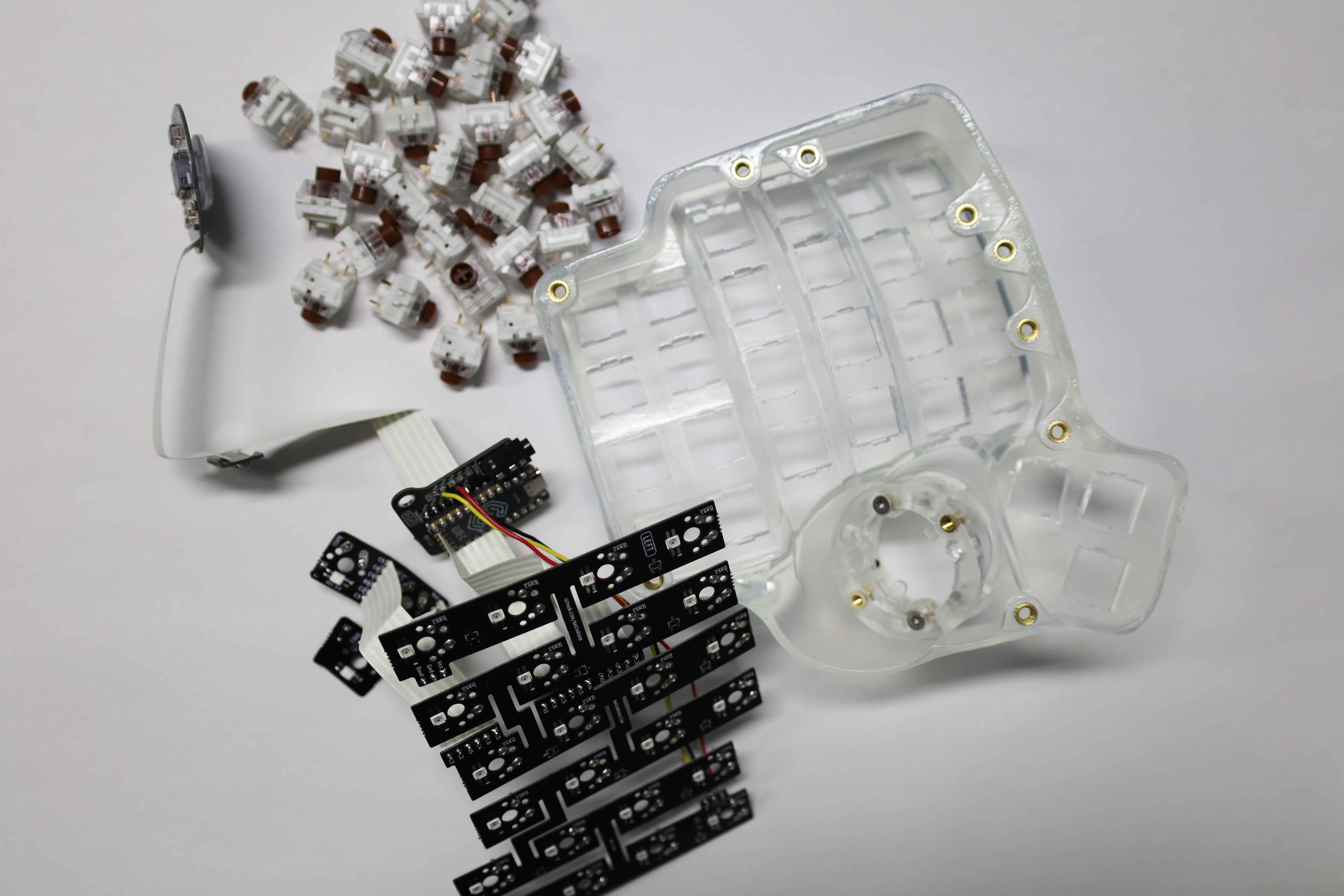
Part List
The following is the list of the various parts and components to source, with an approximate price as of May 2022 for reference. The components to order might vary depending on the degree of customization might desired (different 3D case printing ? different key switches ? with or without hot-swap / micro-controller socketing ? etc…). But in that case, the following part list should at best serve as a vague reference.
moreover, depending on the builder’s geographical location, there might be better offers or methods of acquisition for those various parts.
| Part and quantity | Core build | Case 3D print | Key hot-swap / MCU socketing [Optional] | Price |
|---|---|---|---|---|
| Charybdis electronics kit: Base kit + Per key RBG + Elite C $\times$ 2 + Trackball (Note 1) | ✓ | ~\$270 | ||
| Blank transluescent DSA keycaps $\times$ 56 [Yusha Kobo] [Talp Keybaord] | ✓ | ~\$45 | ||
| Kaihl Pro Purple $\times$ 56 | ✓ | ~\$41 | ||
| TRRS Cable $\times$ 1 (Note 2) | ✓ | ~\$10 | ||
| USB Type C-to-A $\times$ 1 (Note 2) | ✓ | ~\$9 | ||
| 6L IPA for 3D prints cleaning (Note 2) | ✓ | ~\$26 | ||
| FormLabs Resin Clear v4 | ✓ | ~\$150 | ||
| Clear UV Cut Coating $\times$ 2 | ✓ | ~\$10 | ||
| Sand paper for 3D print polish | ✓ | |||
| Mill-Max 0305 Holtite for Switches - Hotswap Sockets $\times$ 100 (Note 3) | ✓ | ~\$18 | ||
| MCU header sockets pair $\times$ 3 + 24 pins $\times$ x 3 (Note 4) | ✓ | ~\$50 | ||
| Other fees (Note 5) | - | - | - | ~\$60 |
| Total | ~\$689 |
Notes
- (Note 1): The case is not included. One might print their case, or also purchase it directly from the website as a different kit. There is also a “Prebuilt” option.
- (Note 2): General enough products that do not warrant a link … unless one might be interested in also DIY-ing the cables.
- (Note 3): Already have some from the previous build, so 100 were enough. Strictly speaking, however, one would need to order $56 \times 2$ thus $112$ to have enough for all the keys.
- (Note 4): For the Shield v2, each Elite-C will require $12 + 12 + 5 = 29$ header sockets, and the corresponding 29 pins.
For the
Shield v1version, the Elite-C requires $12 + 6$ header sockets and the same amount of pins. The headers in the provided link are 12 pins header sockets that are sold as a pair. The pins are also sold as a set of $24$, to match the header sockets. As of 2022-06-14, it seems that the Shield v2 will be the default, so this post will use that one as a reference from now on. This will, unfortunately, cause some surplus when ordering the components for socketing the Elite-Cs, but they can be used to socket other components, such as the various ribbon cable, and RGB cables. To save up on the pins, one could also use some LED legs instead. - (Note 5): Depending on the geographical location, not only the prices part, but also the import tax, various other taxes, and shipping fees can add up to a non-negligible amount.
Build log
DISCLAIMER This should not be considered as a build guide, but as an additional reference with some notes regarding the special cases and problems encountered through the build, that might not be self-evident during the conceptual phase or planning of the keyboard build. Ultimately, it is more of an attempt to document what worked well during the process, as well as the mistakes made along the way.
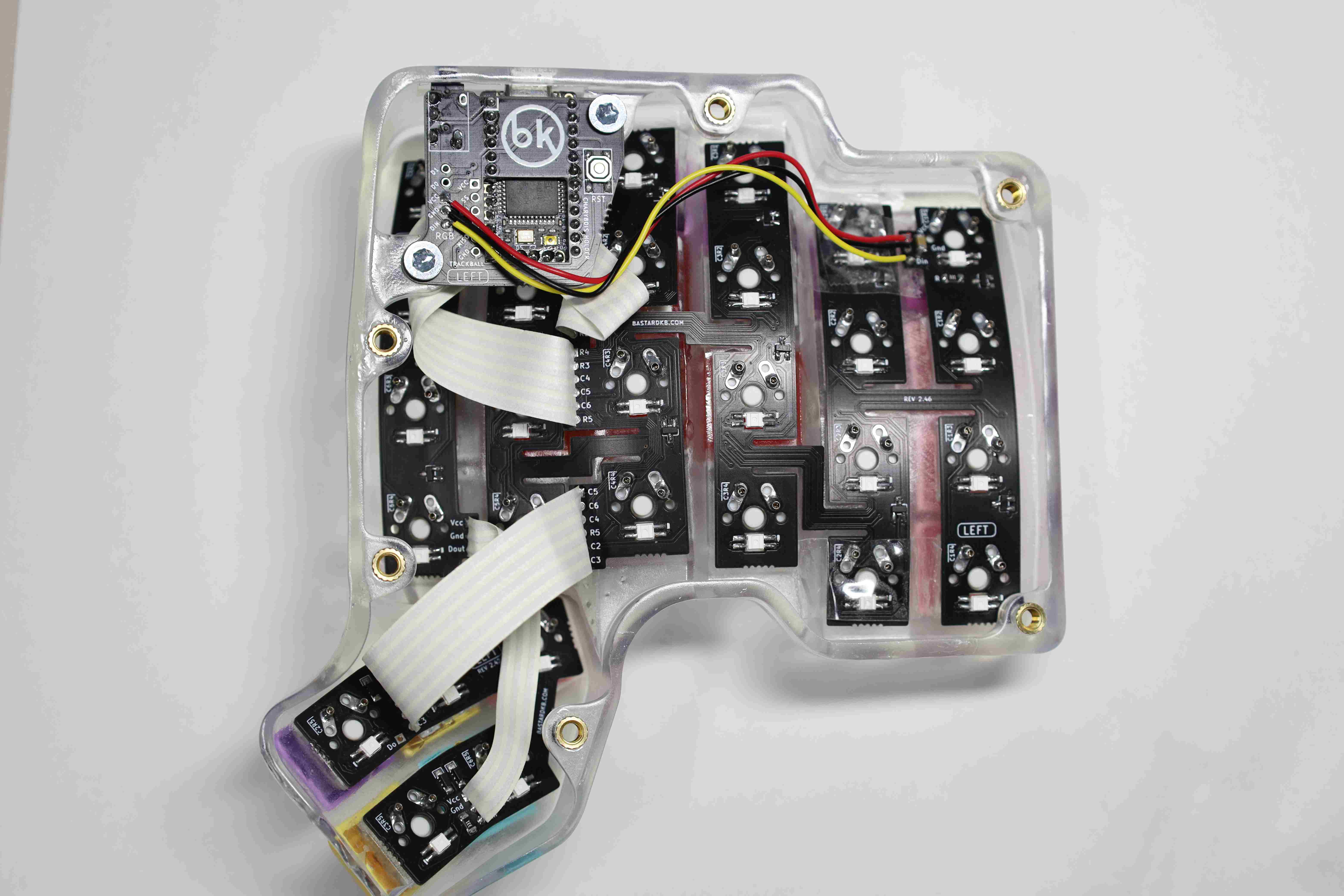
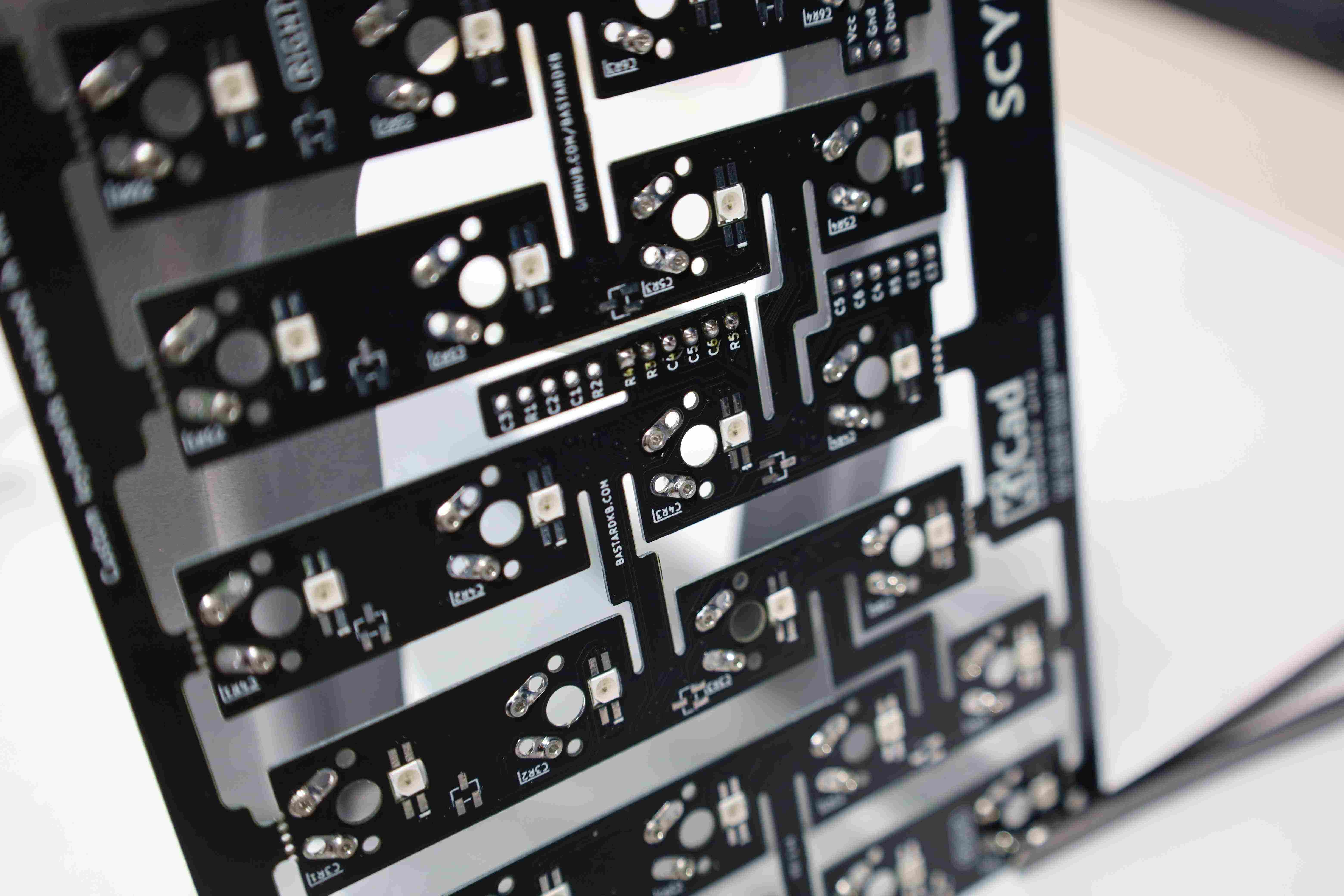
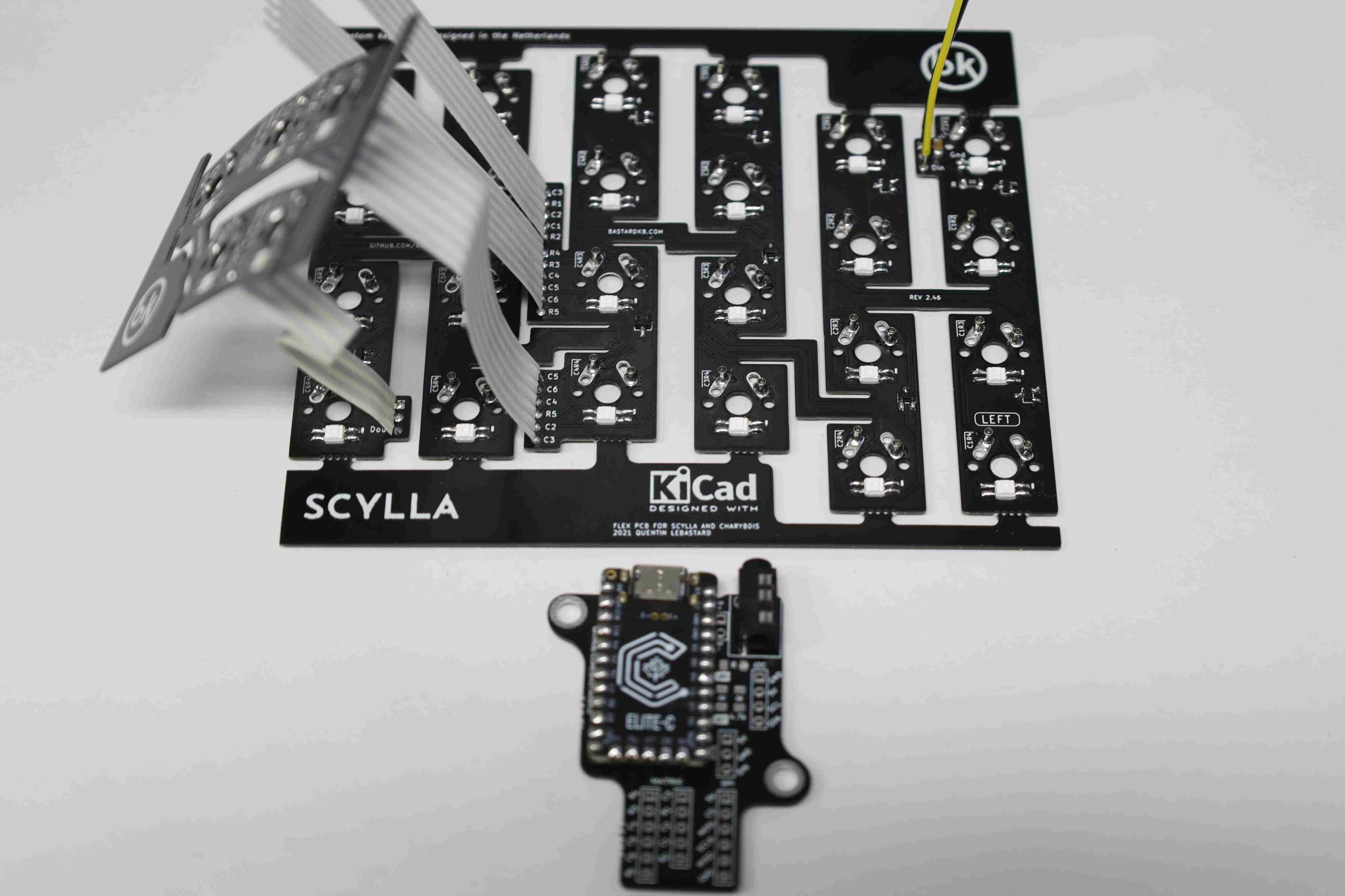
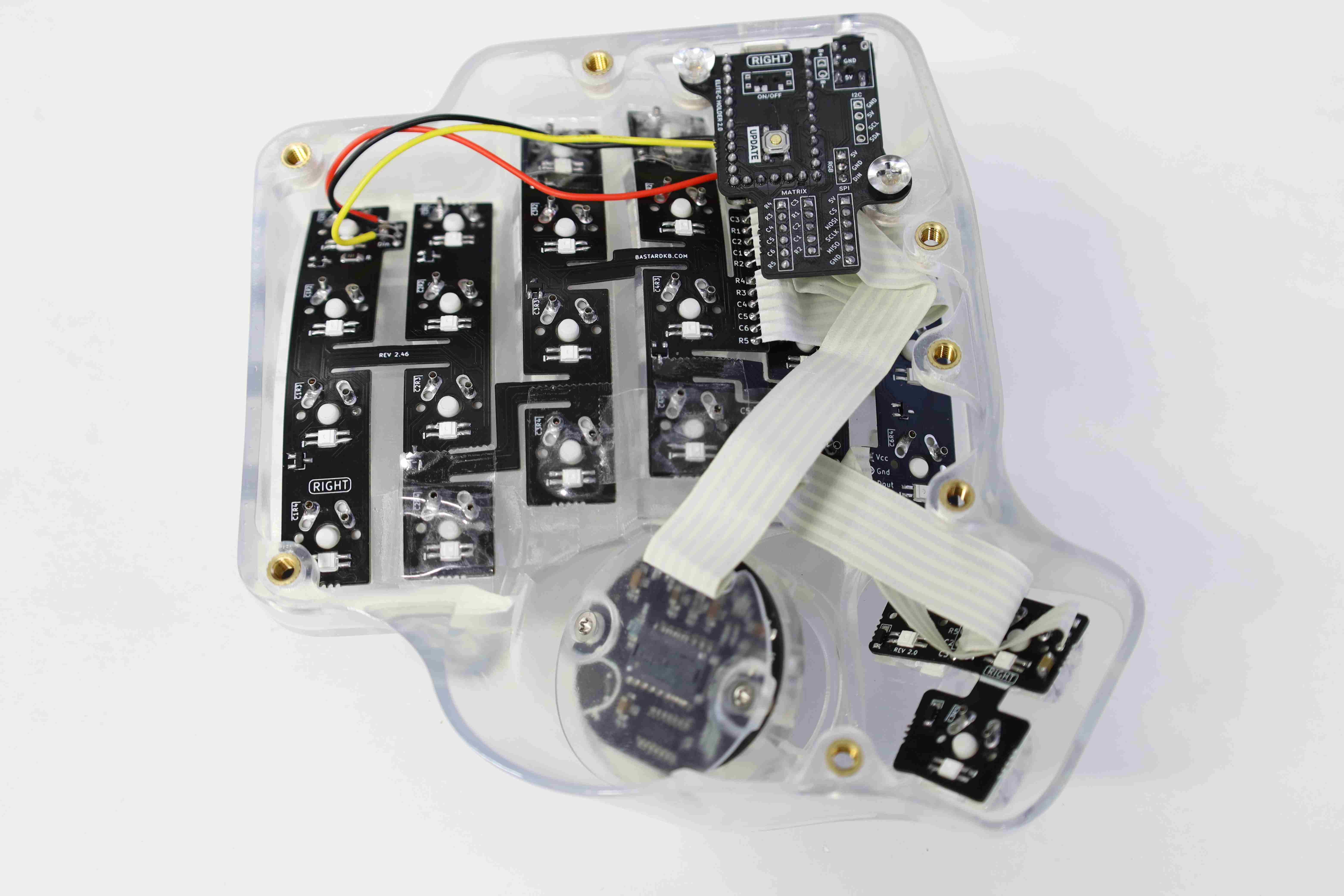
Rigorously, the Charybdis refers to the side of the board that holds the trackball, while the other side is a Scylla board, which does not have a trackball. In this build, the left side uses the Scylla board, while the right side uses the Charybdis with the trackball. This build has the optional RGB, MCU and key switches socketing, and custom 3D printed cases.
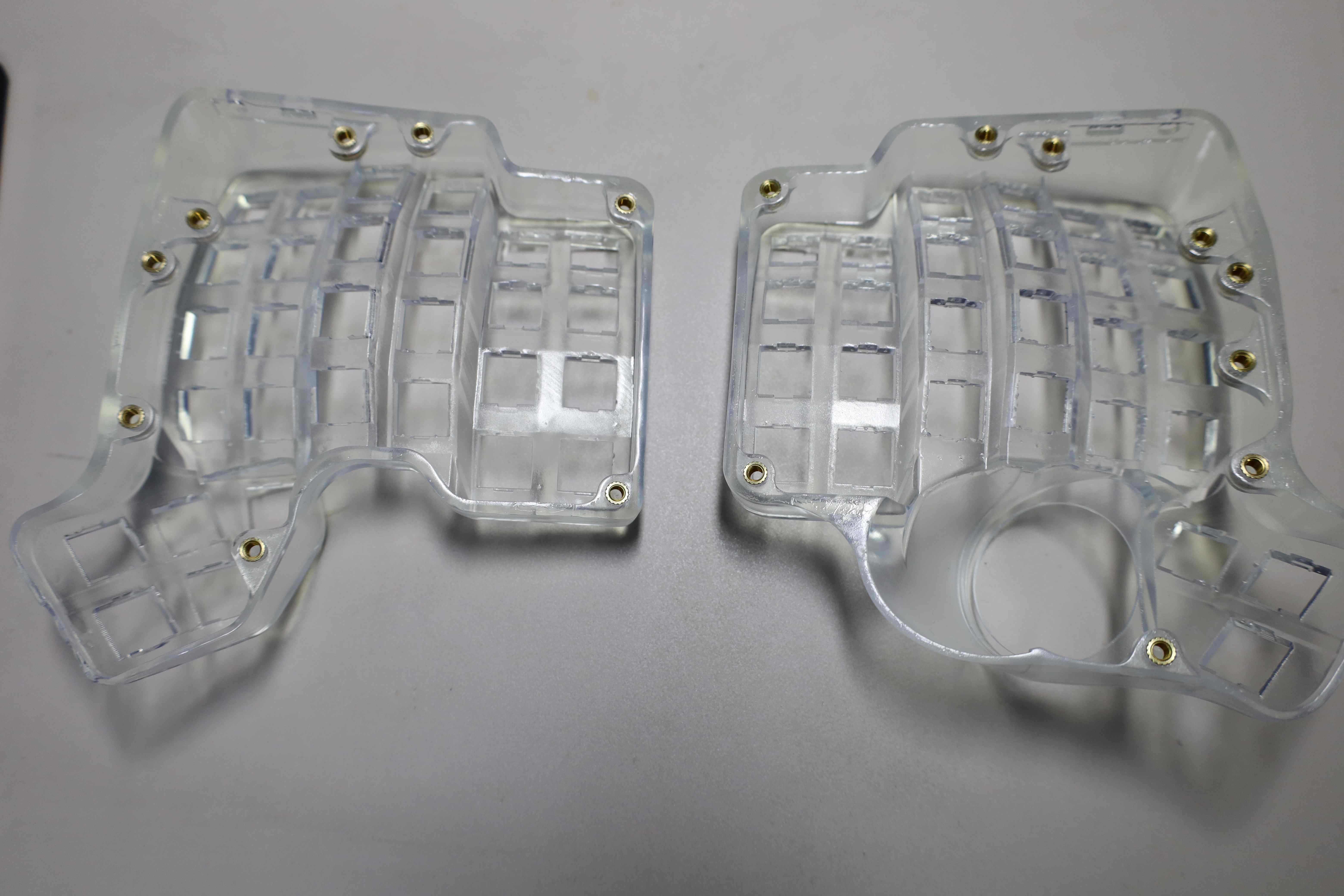
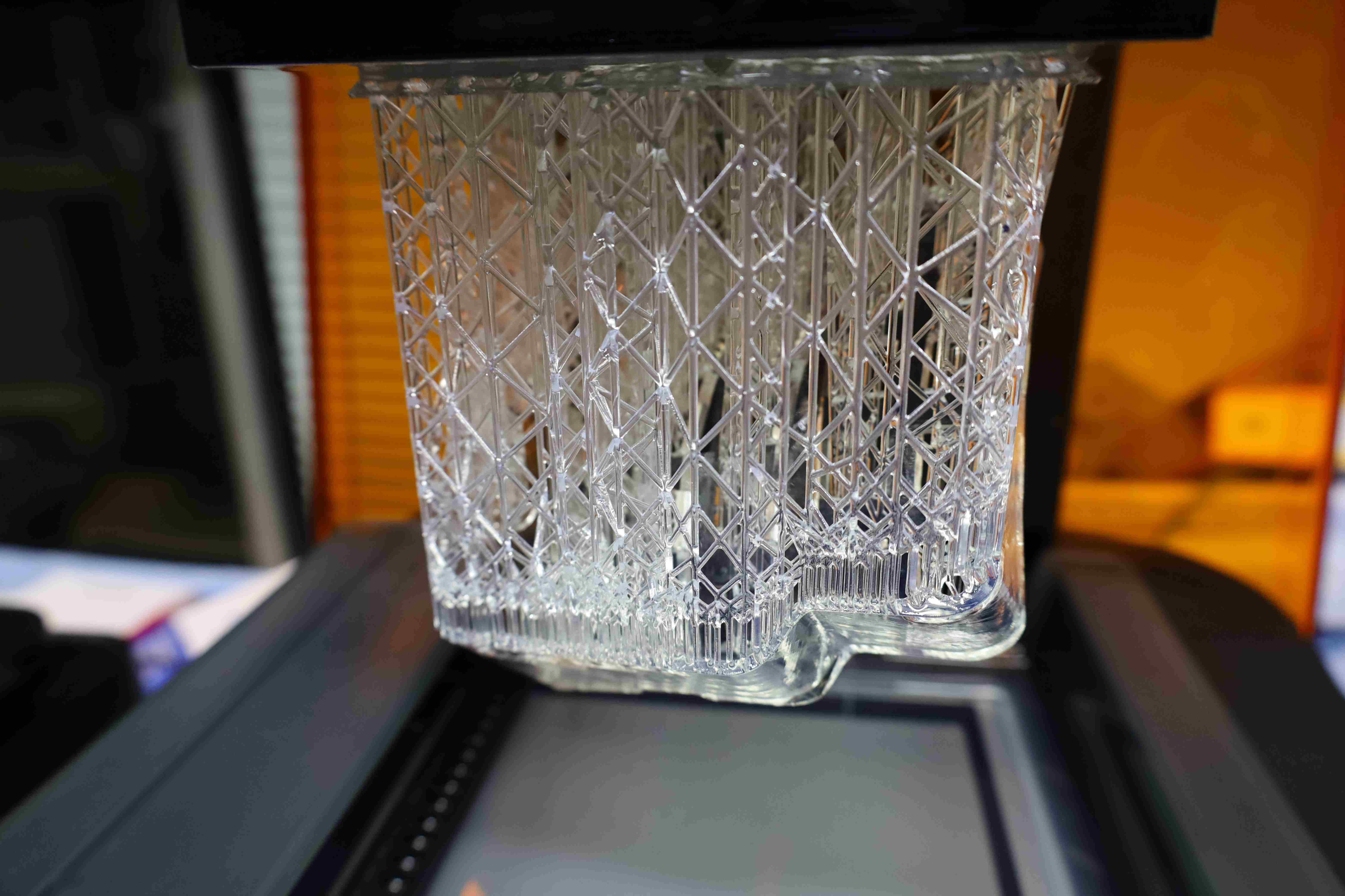
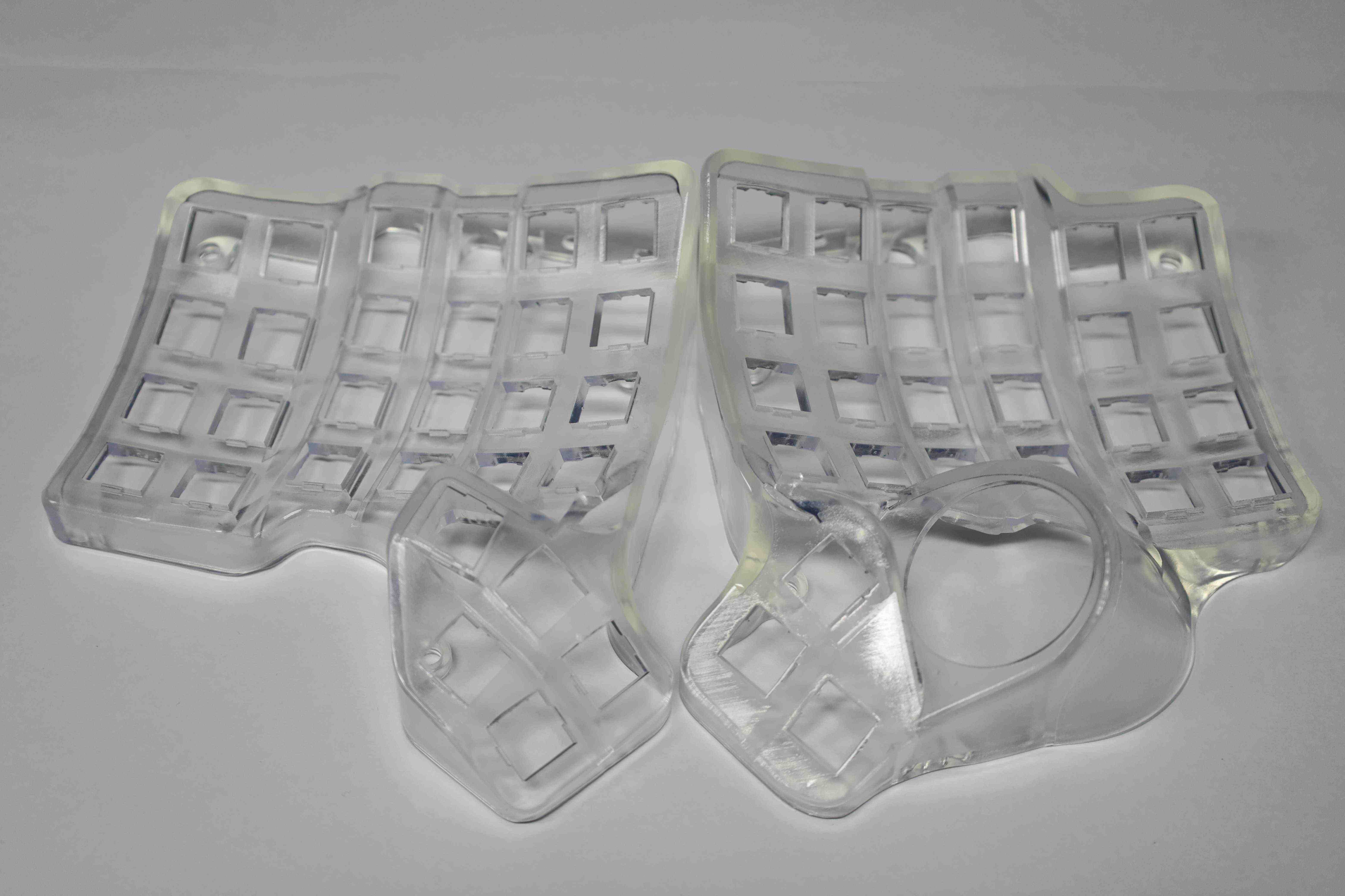
1. 3D printing the cases [Optional] [Left, Right]
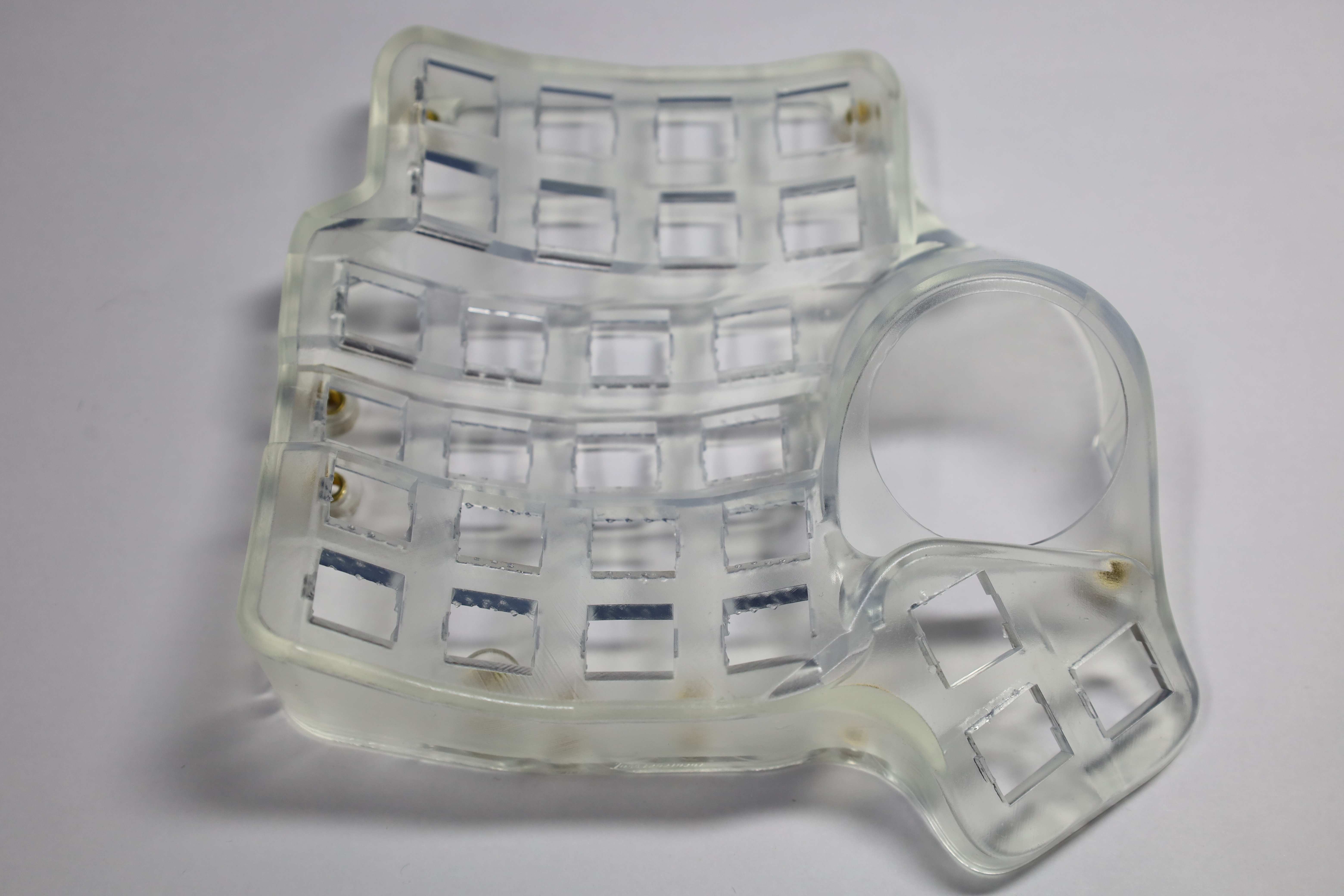
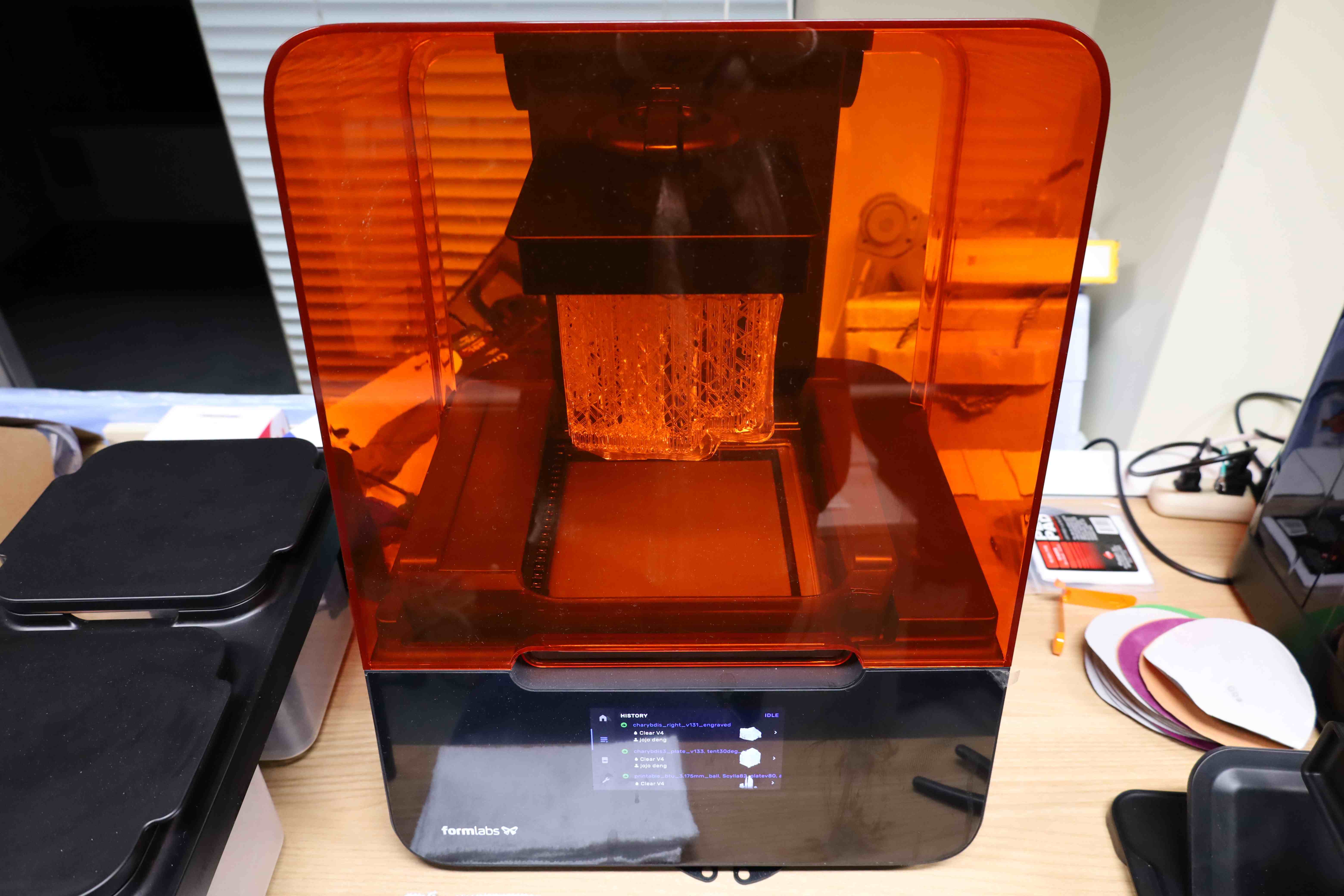
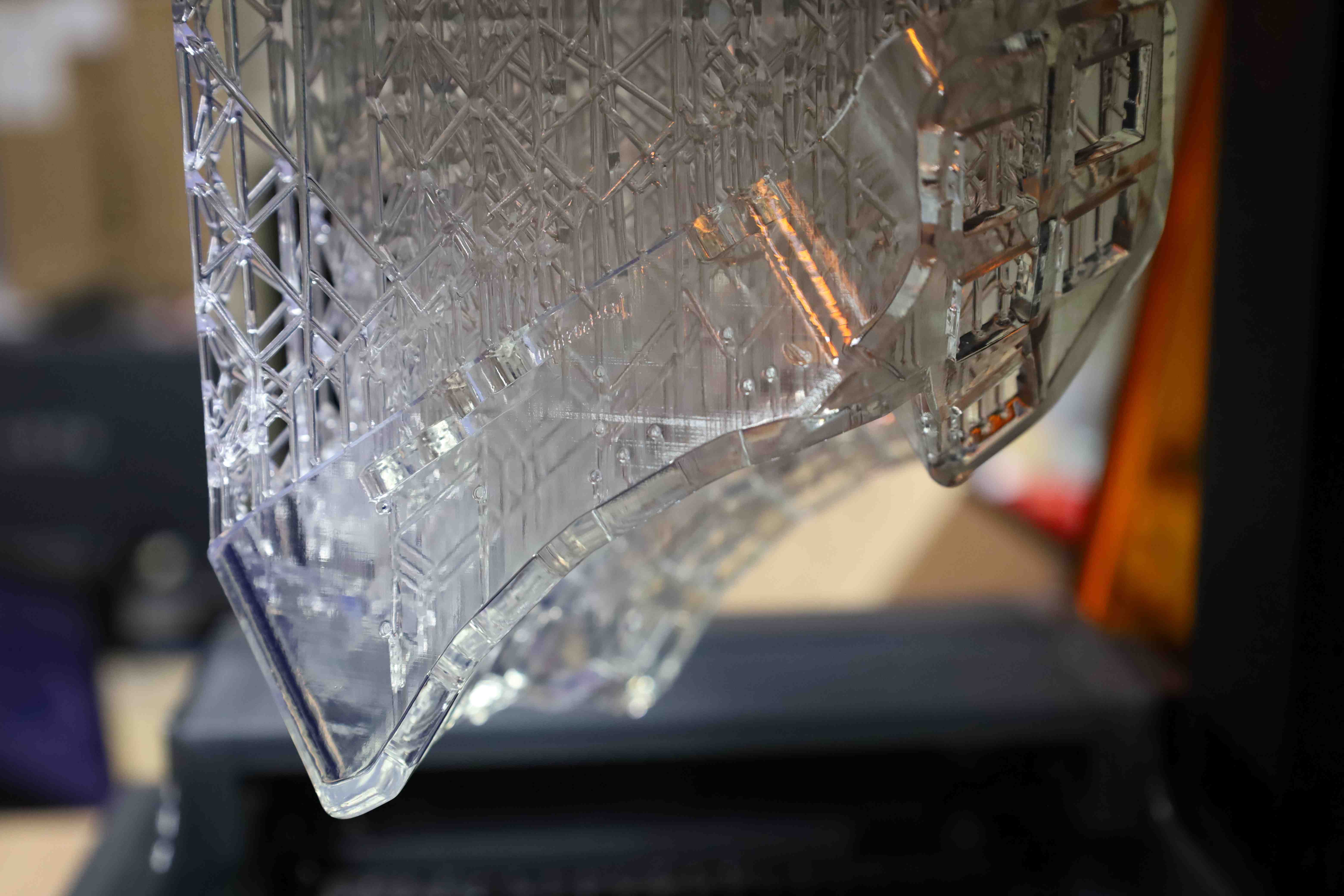
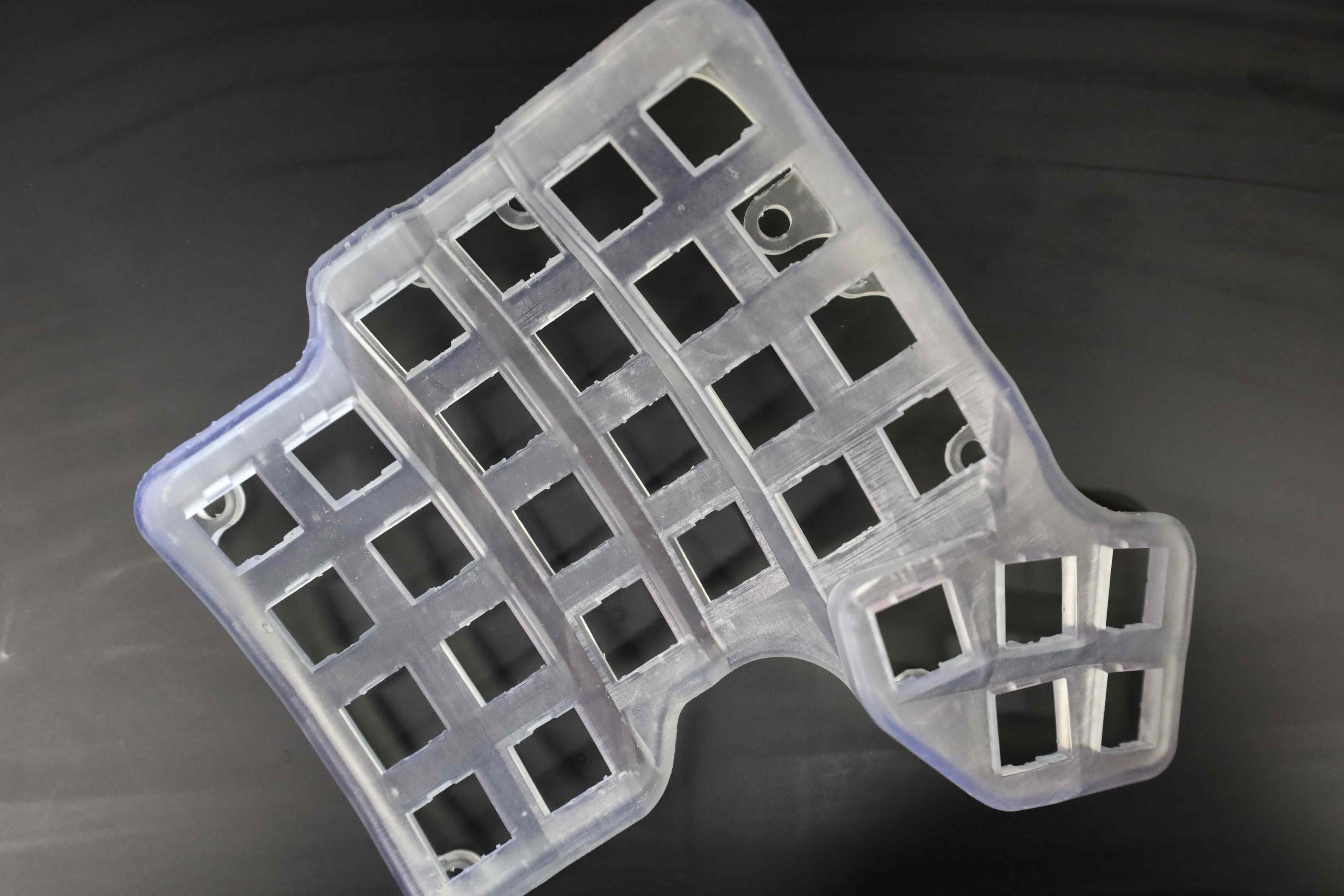
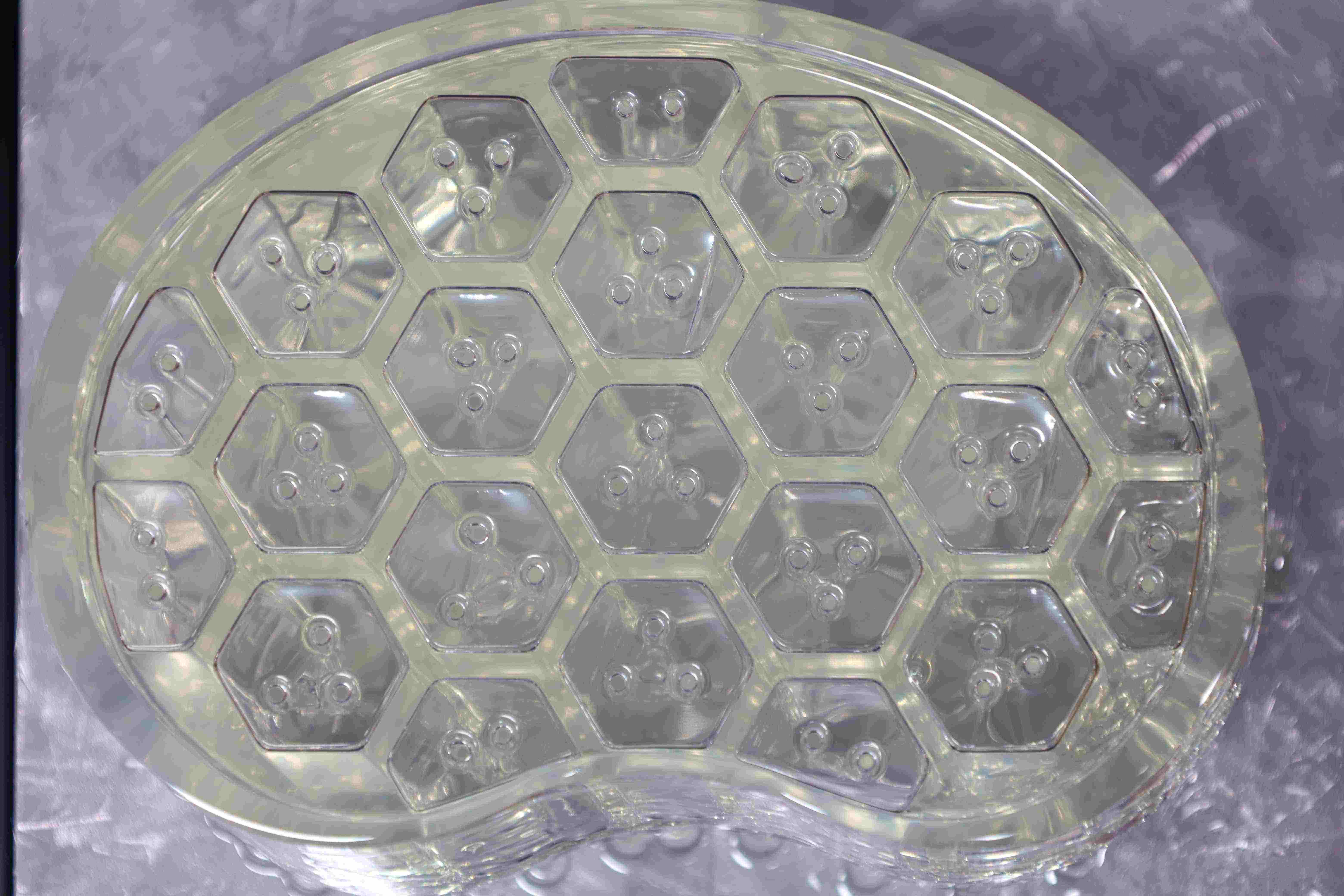
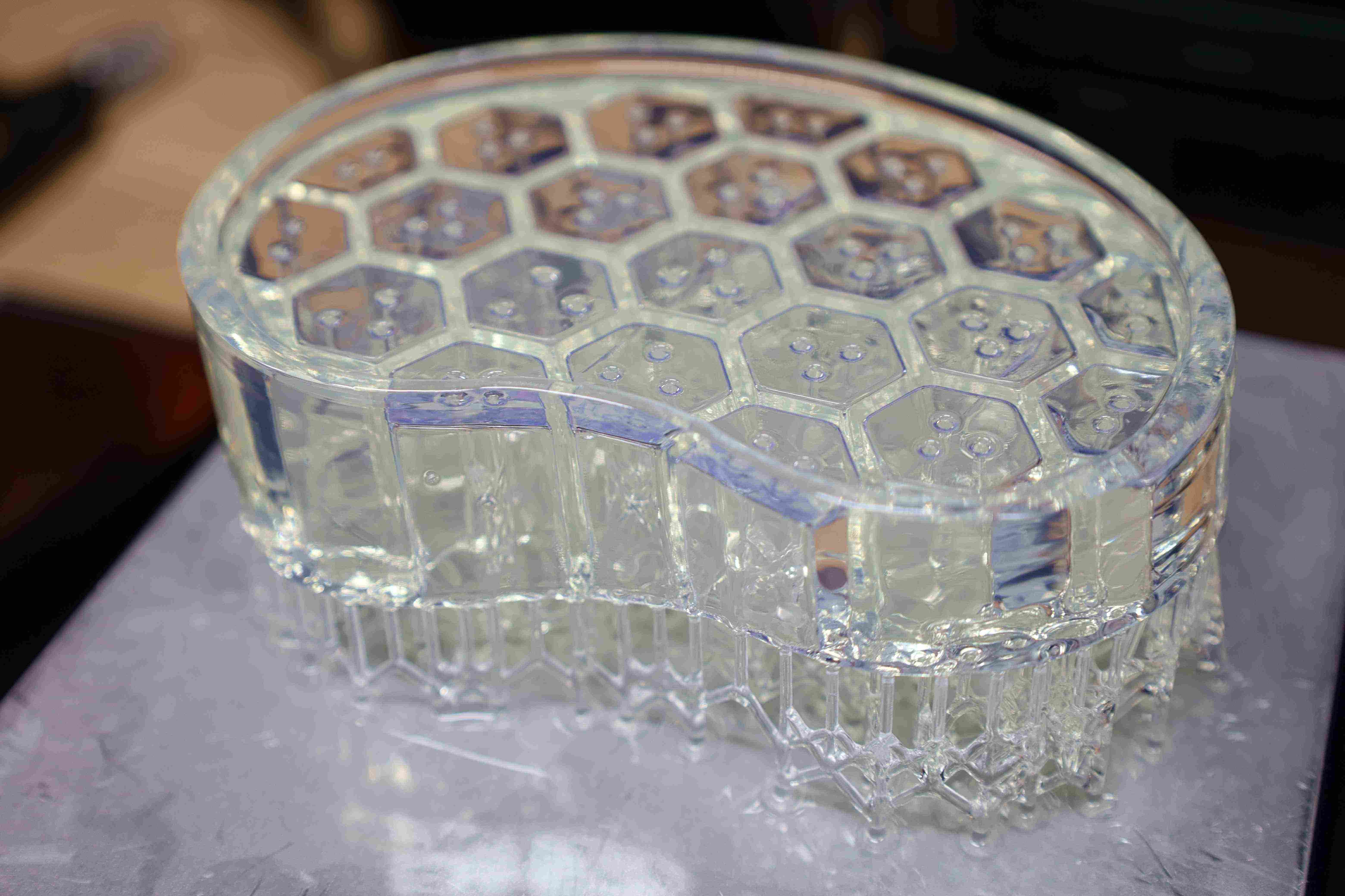
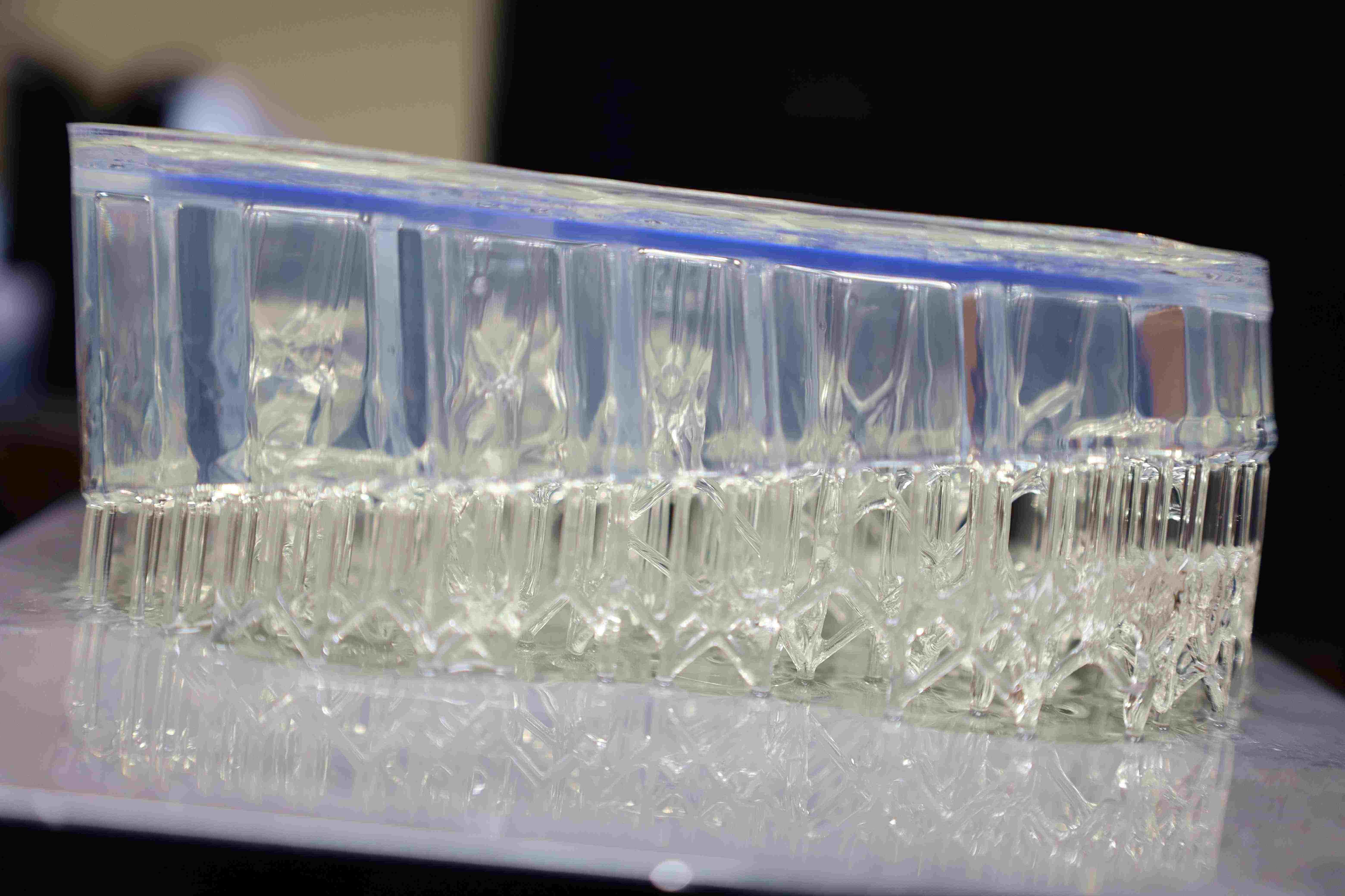
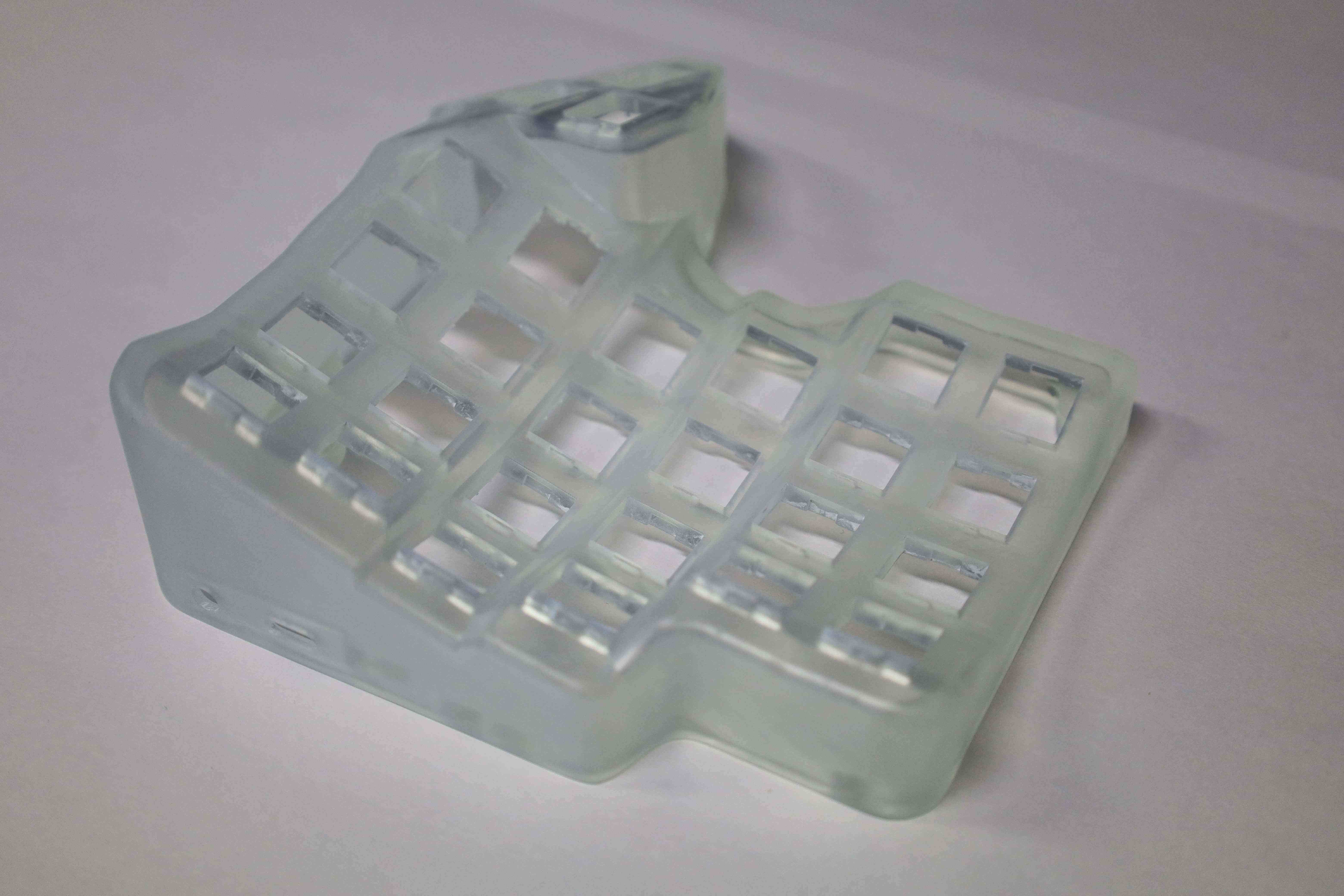
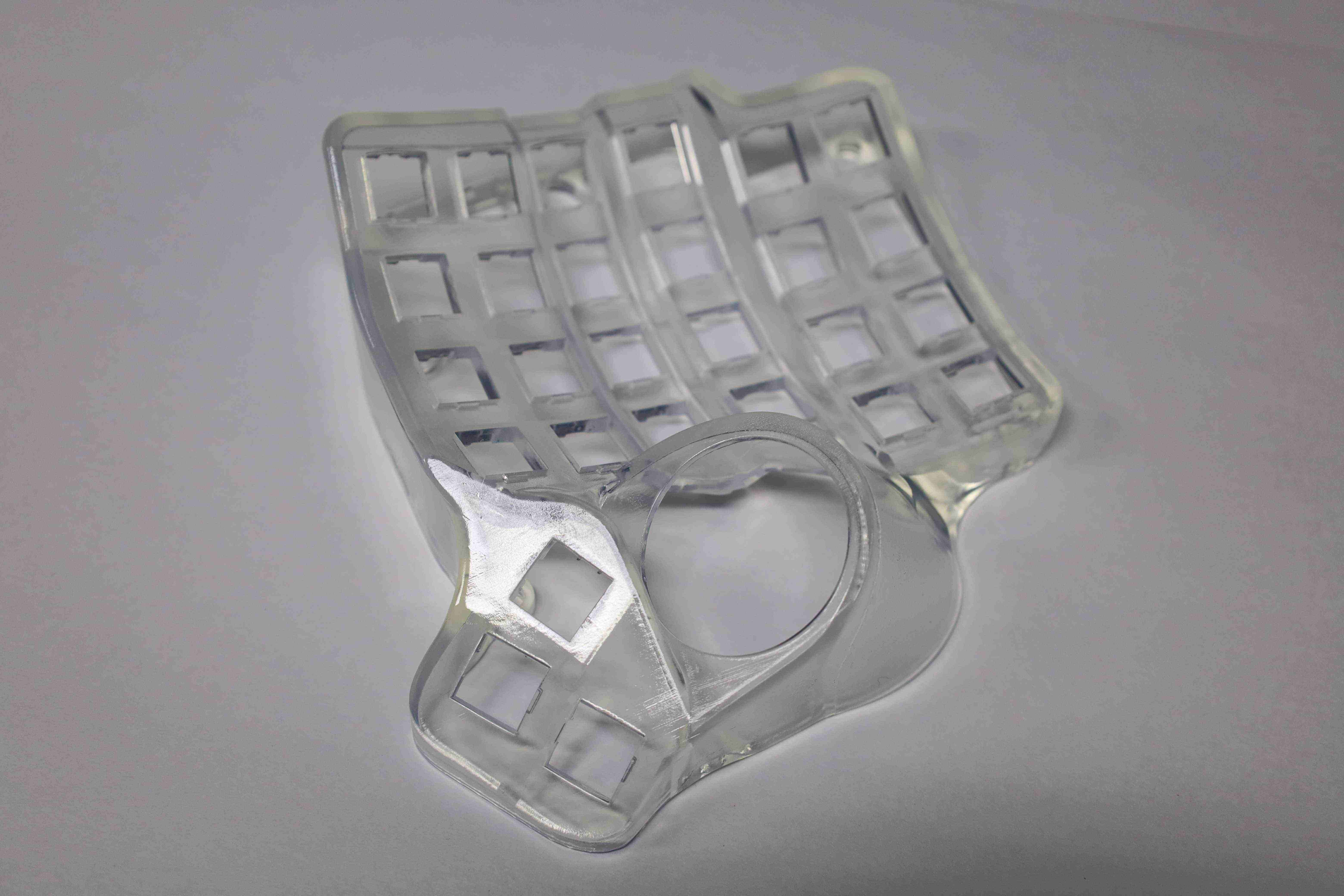
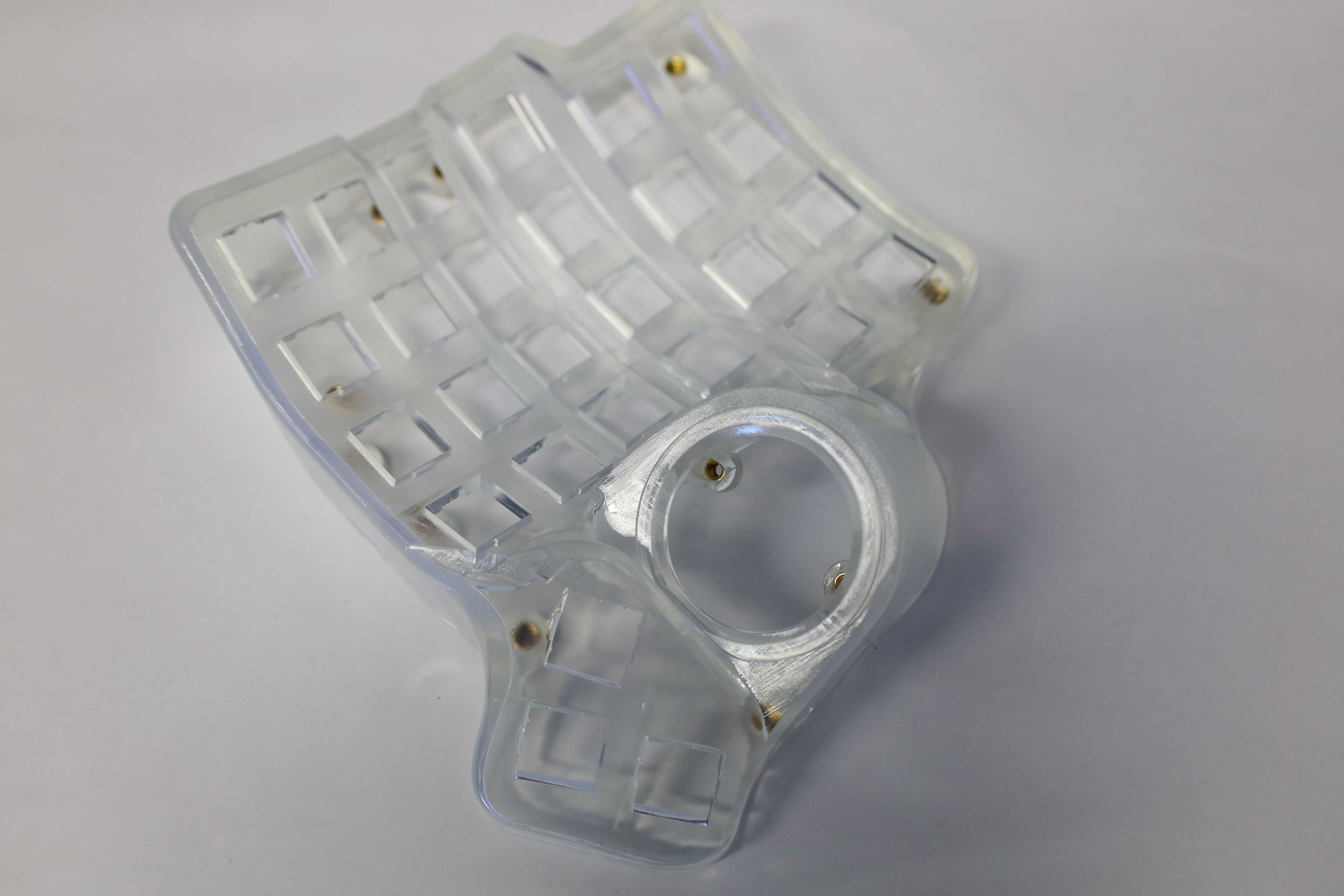
For this build, the clear cases were printed using a FormLabs 3 SLA printer. The material used was the Clear v4 Resin. The files to 3D print are generously provided on the official GitHub repository in the STL format.
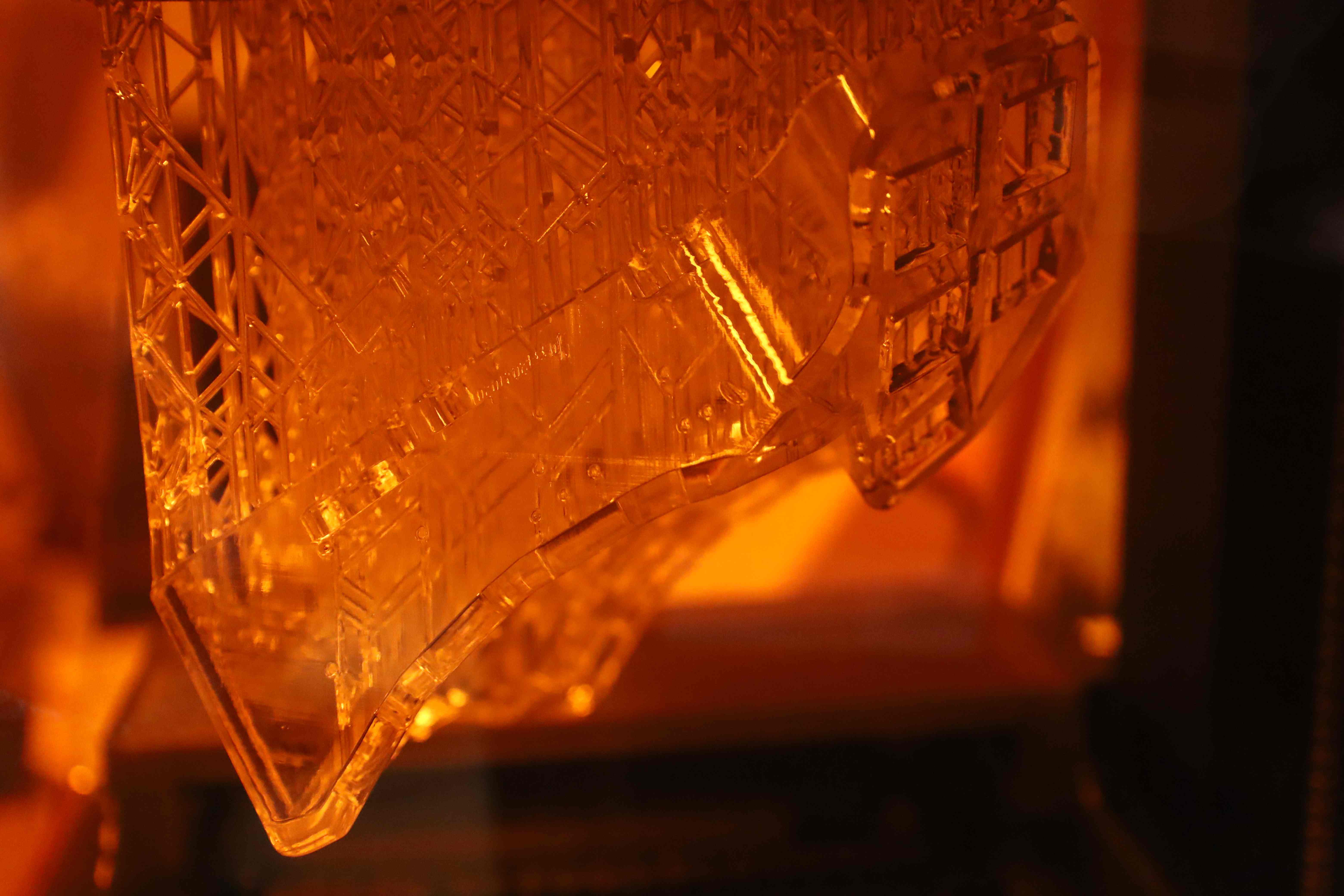
In an attempt to have an ever more customized keyboard, I also engraved my nickname using Blender before printing the customized 3D files on both Left and Right sides.
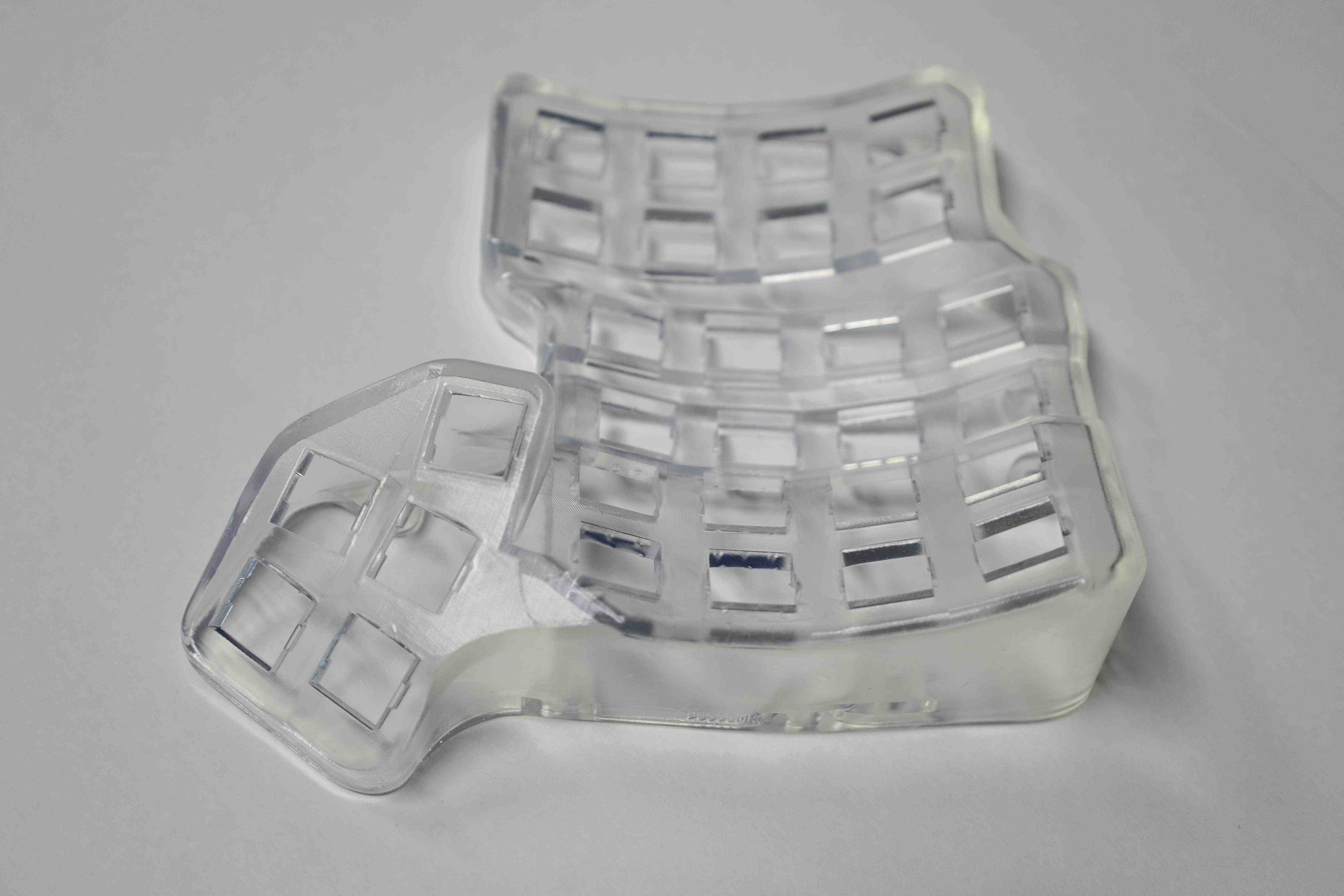
Finally, as I planned to heavily rely on the tenting solution, I used the wrist rests open-sourced by dereknheiley and added some infills to make it less expensive to print. The wrist rests were made a bit taller to match the height of the tents, with some manually added infills to save up resin. Ultimately, I ended up relying on the armrest of the office chair I am using to elevate my hands enough to match the height of the tented keyboard.
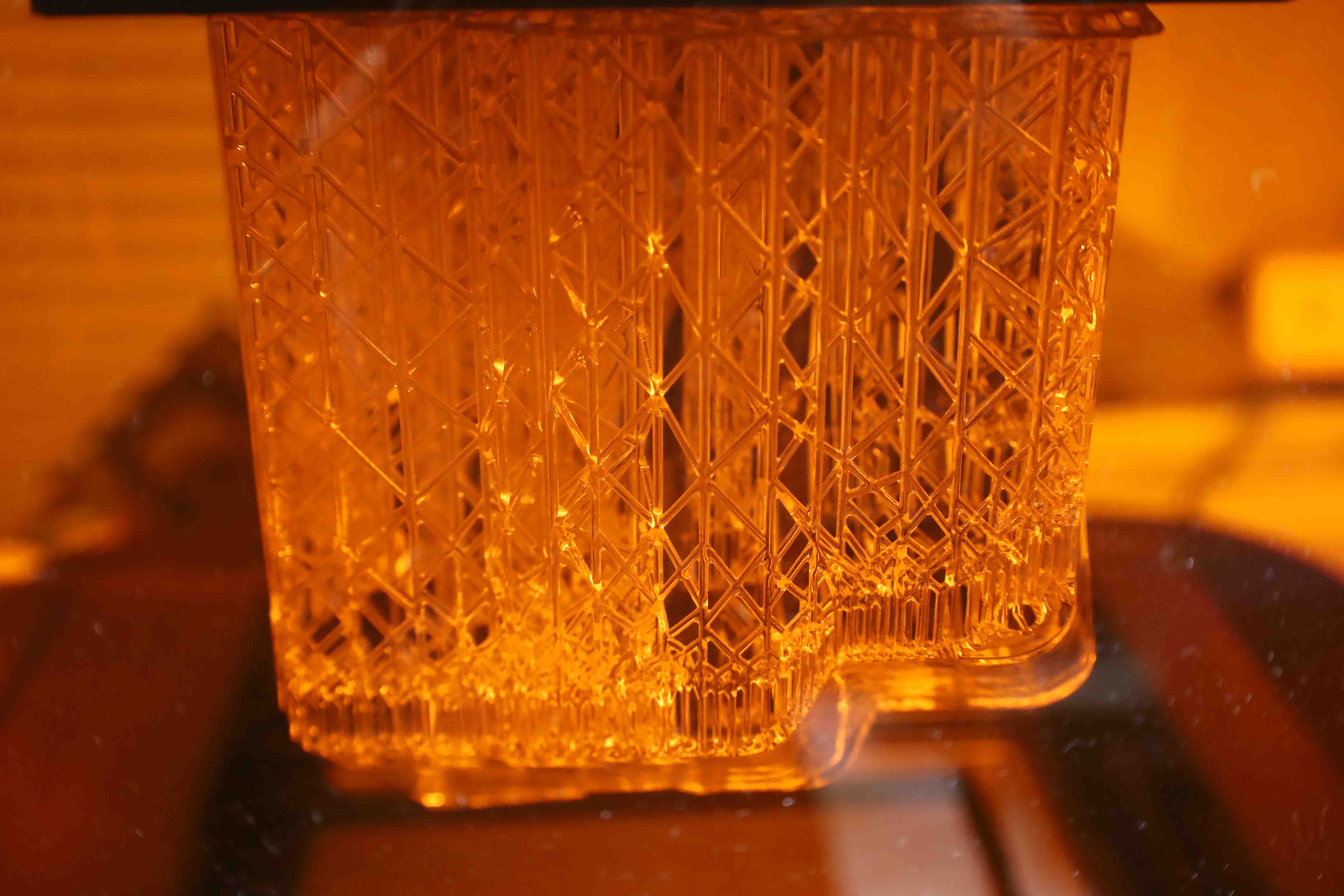
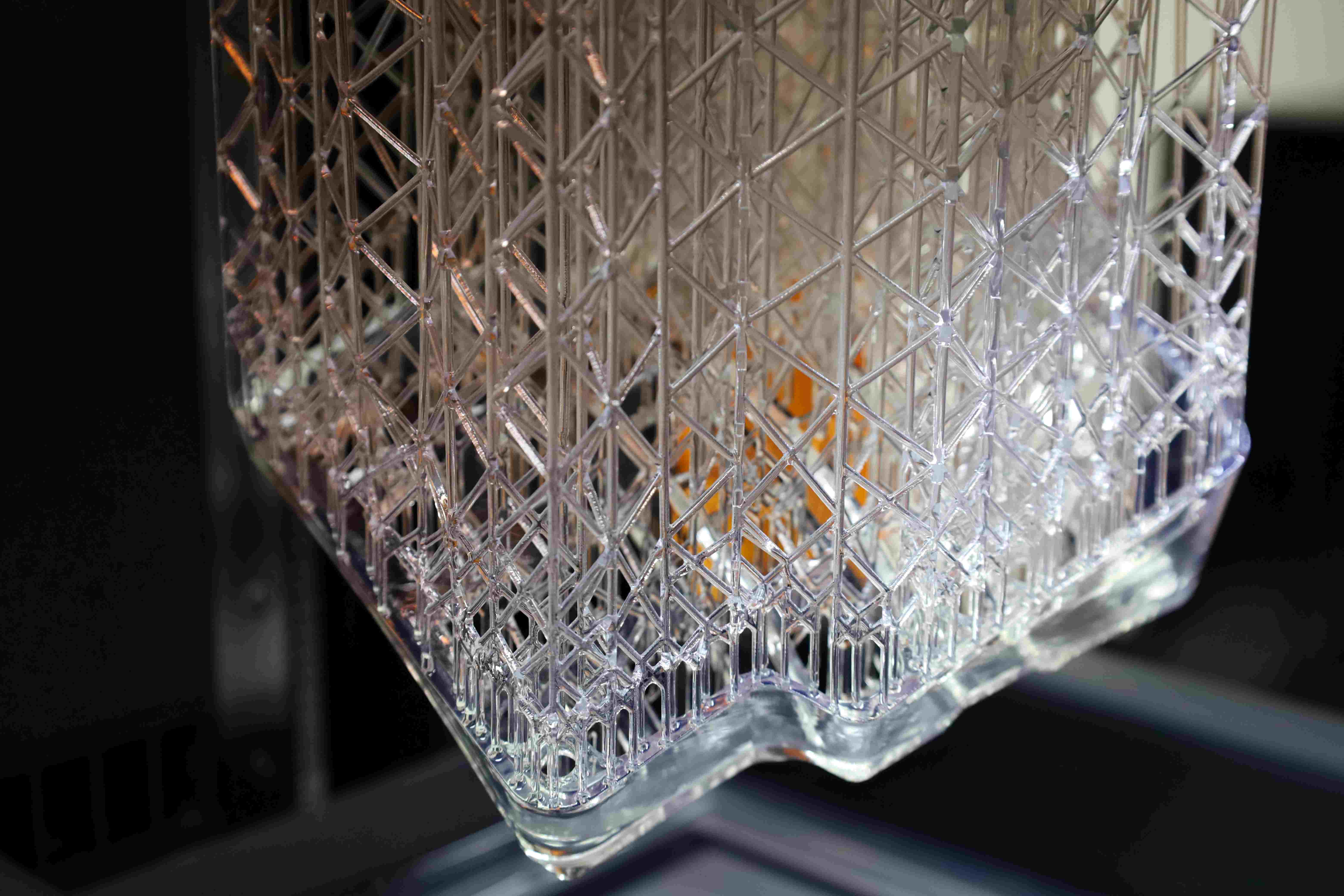
Printing with a FormLabs printer requires the STL files to be sliced with the PreForm software. For this Crystaldis build, the aesthetics of the clear case were relatively important. However, the 3D printing process requires support structures that would be spread arbitrarily over the cases, when using the automatic generation option in PreForm. Then, the supports must then be broken, which unfortunately leaves some small, but hard-to-miss dots and scratches both in and outside the cases. While the outside support remain can be polished out fairly easily, the ones on the inner side of the case can pose some challenges. I ended up manually editing the supports to make the polishing easier. On a side, the automatically generated supports can be overly generous, which ends up costing resin. Meanwhile, a more astutely designed support structure not only helped improve the aesthetics but also reduced the amount of resin used by having less support.
Another important sanity check before printing anything was to make sure of the orientation of the STL files for the case and the tenting. Namely, at the time I cloned the official repository, the case of the Charybdis was set to the left hand by default, which would thus require a mirroring to fit the right-hand side trackball of this build.
I the time of the build, I ended up ultimately really on the following checklist:
- Scylla Case STL: Is it left hand?
- Scylla Tenting STL: Is it for a left hand ?
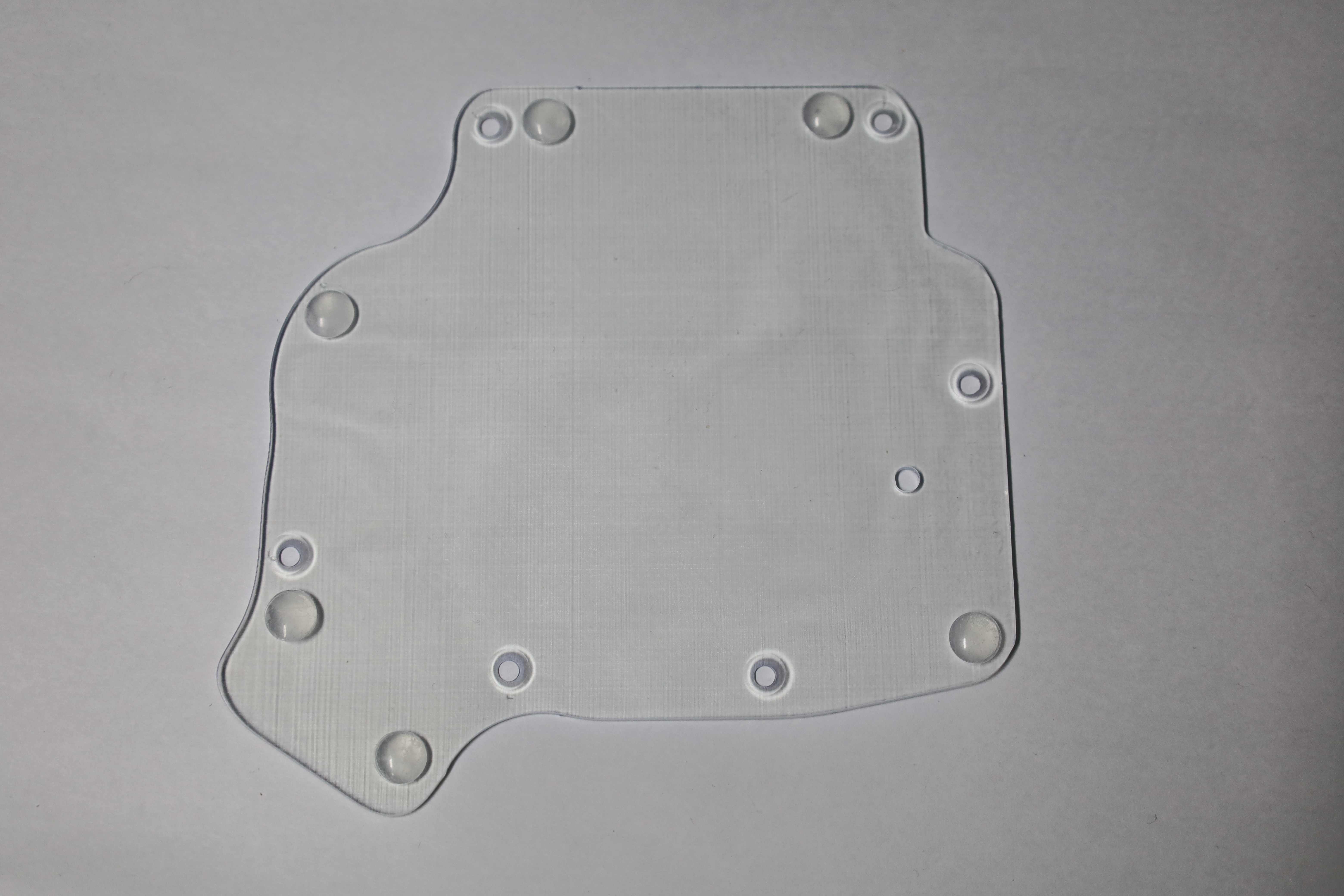
- Scylla Bottom Plate STL: Is it for a left hand?
- Charybdis Case STL: Is it for a right hand?
- Charybdis Tenting STL: is it for a right hand?
- Charybdis Bottom Plate STL: is it for a right hand?
- Charybdis Top Adapter STL: no changes are needed
- Charybdis Bottom Adapter STL: no changes are needed
- Charybdis Sensor Cover STL: no changes are needed
- Charybdis Printable BTU mods: no changes needed
- Wrist rest STL: right-hand check ?
- Wrist rest STL: left-hand check ?
Besides that, here are a few notes regarding printing with a FormLab 3 using the Clear v4 resin:
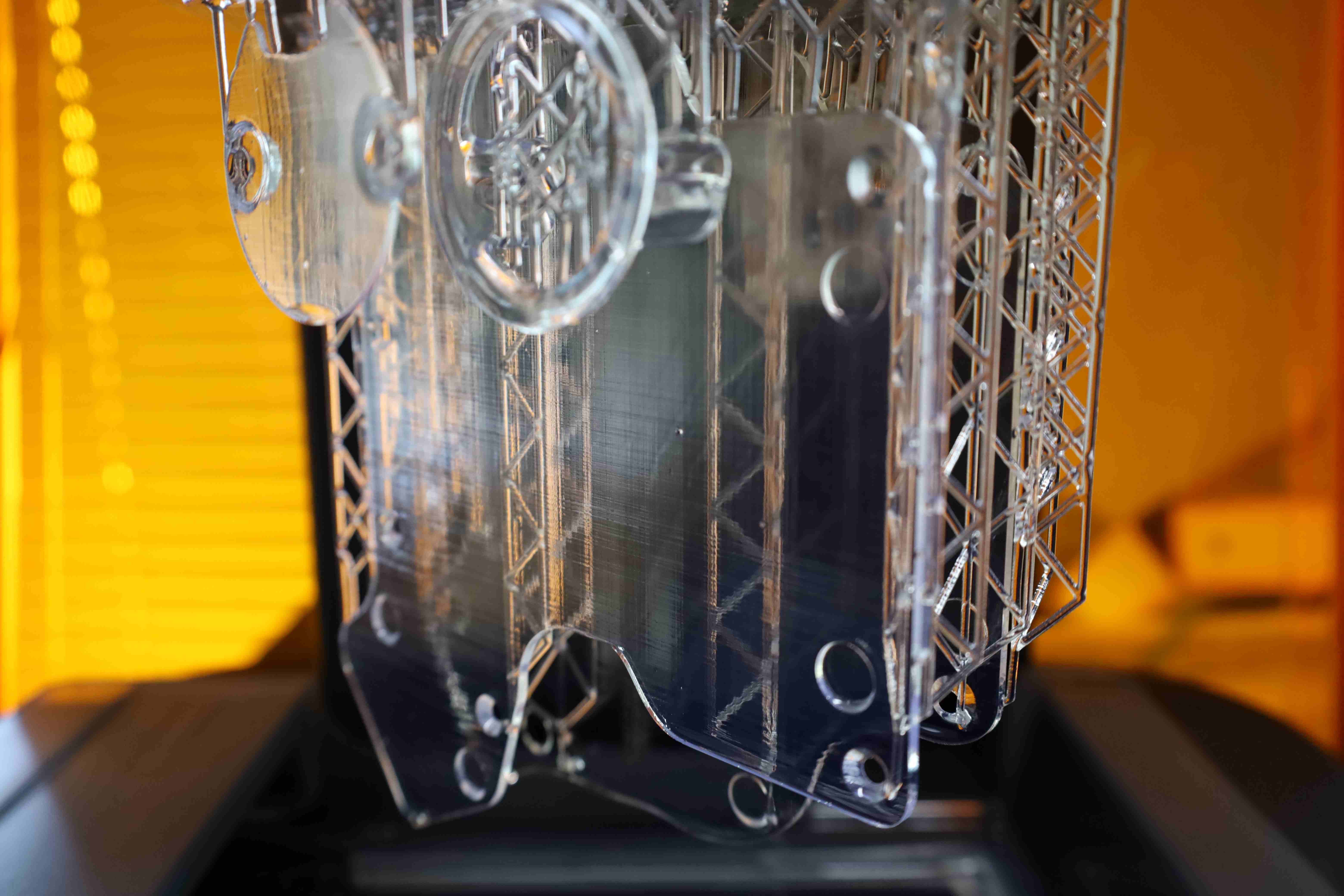
- Once the print is finished and taken out of the printer, remove the print from the build stage as soon as possible. Otherwise, the ambient UV rays will make the support structure in contact with the build stage solidify, thus making the removal process akin to torture.
- If the aesthetics of the print are important (clear case for example), then manual support editing might not only save up in resin, but make the polishing result more efficient, and the overall product seamlessly transparent.
- When designing the support structure manually, using mini-raft and slightly reducing the density of the support can make the removal process easier. Using a smaller support touch point of around $0.42$ can also help reduce the pain of the polishing. However, further reducing the touch point size can lead to the failure of the prints.
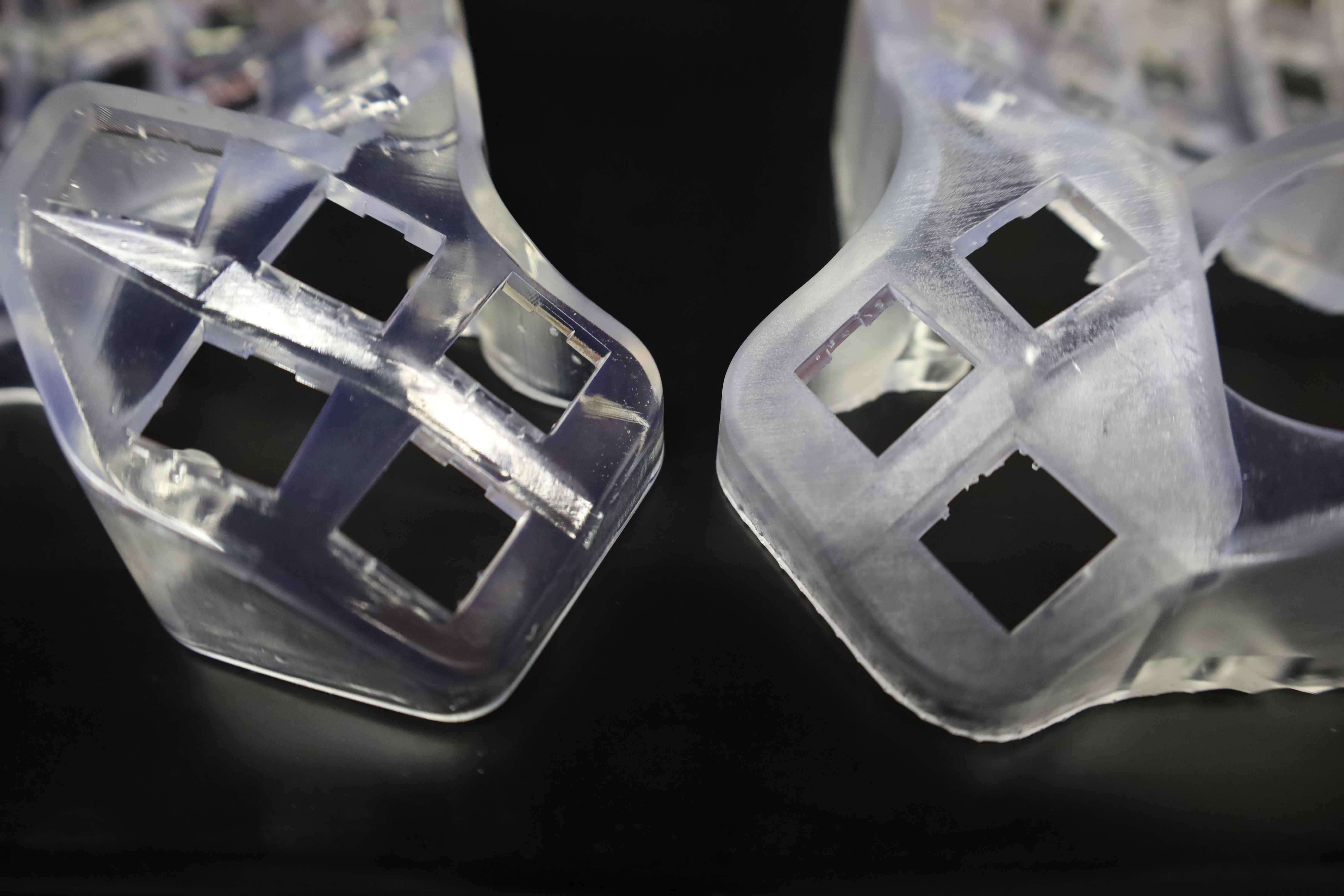
- Curing the prints with UV and heat (using FormLabs Cure) even for a few minutes will make the case yellowish. Fortunately, the printed cases and other components were already solid enough by themselves to skip this step and conserve a more natural color.
- For clear prints, polishing and then applying some clear UV cut coating is a must. The clear coating improves the glossiness and transparency of the print, as well as protects the case from yellow across time due to ambient UV rays. Before the prints are coated, it would be better to keep them hidden from sunlight or other UV ray sources.
As a reference, the print-ready PreForm files for this keyboard can be found in this GitHub repository. Note that the cases as engraved with my nickname, so I would not recommend re-using the PreForm as they are.
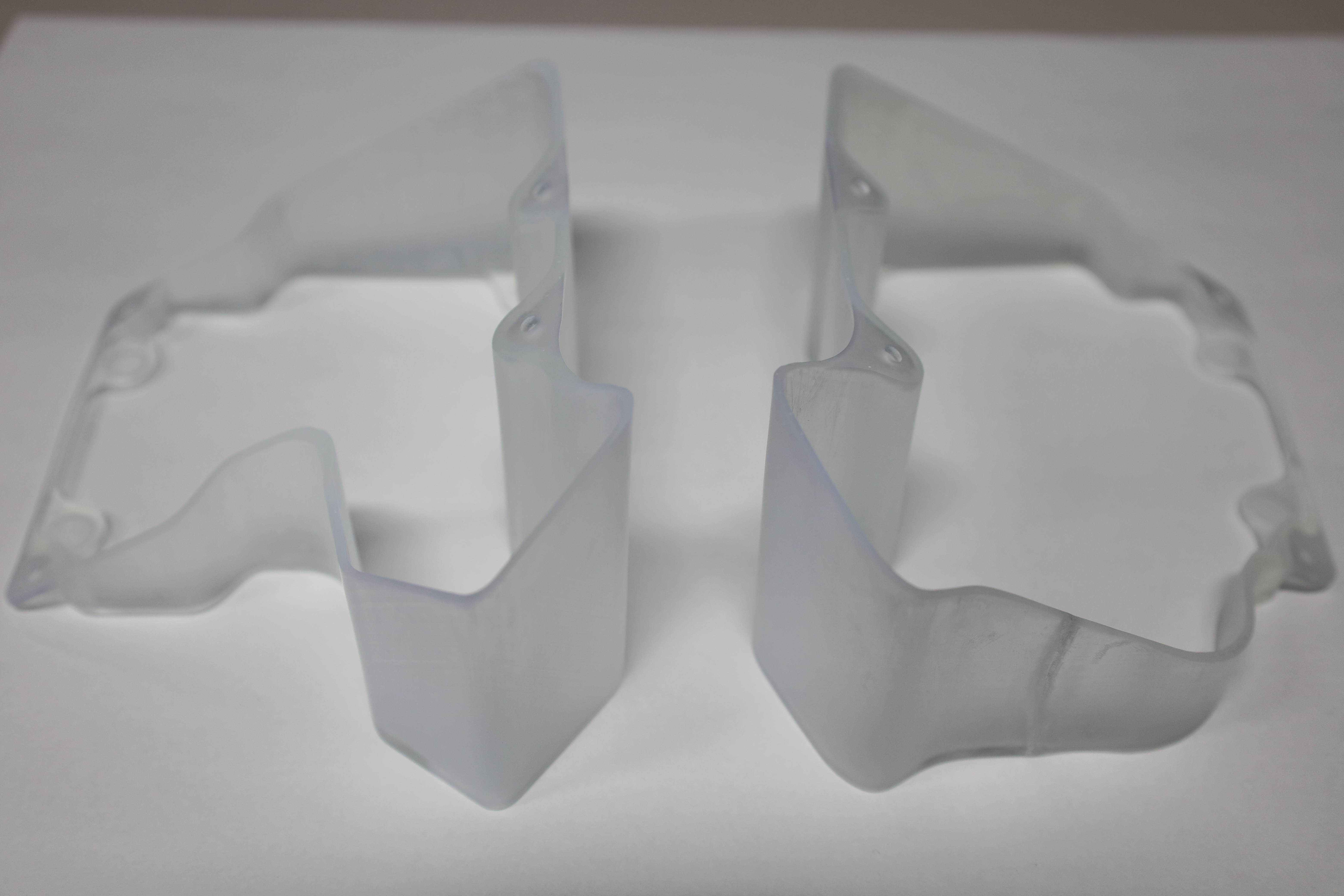
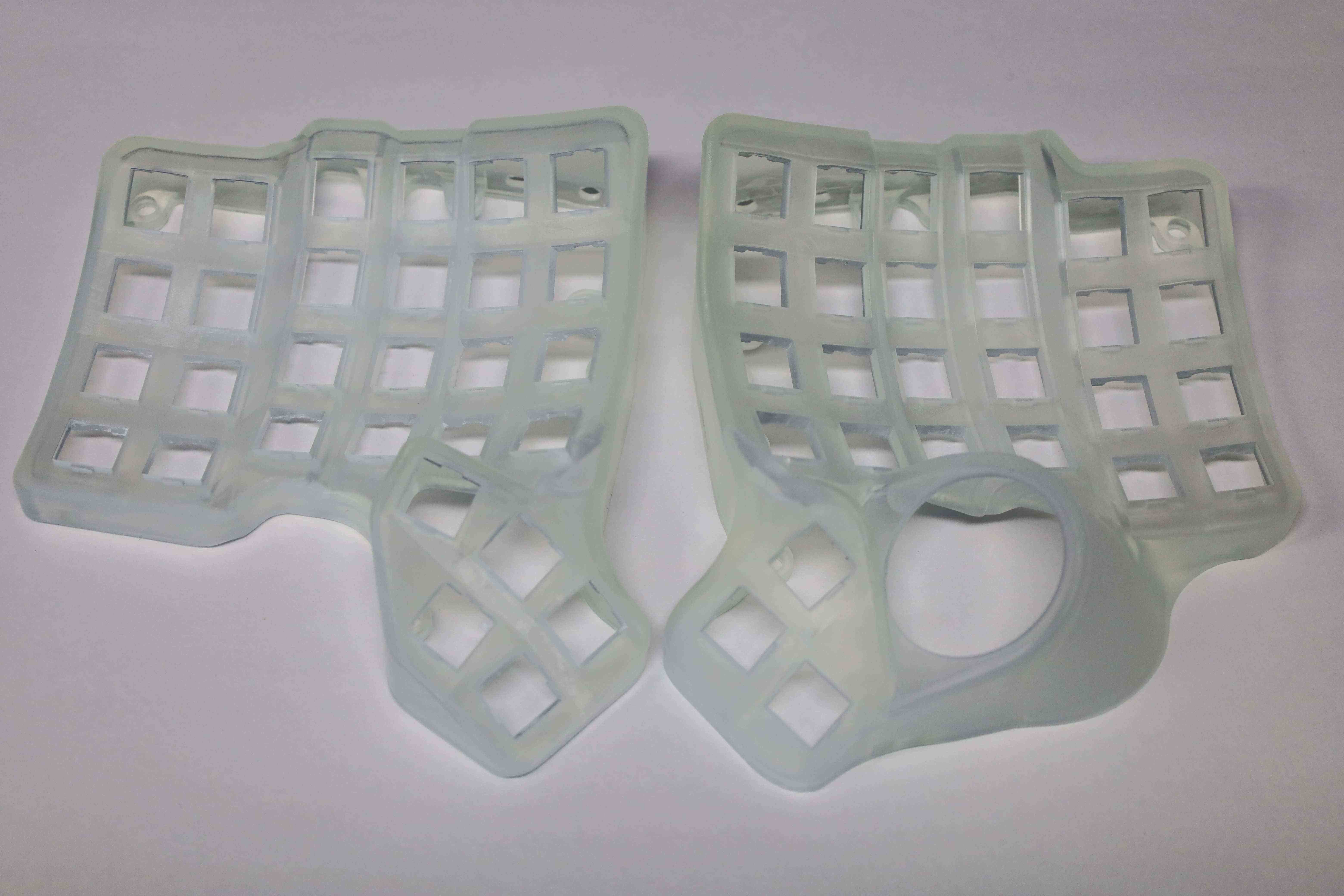
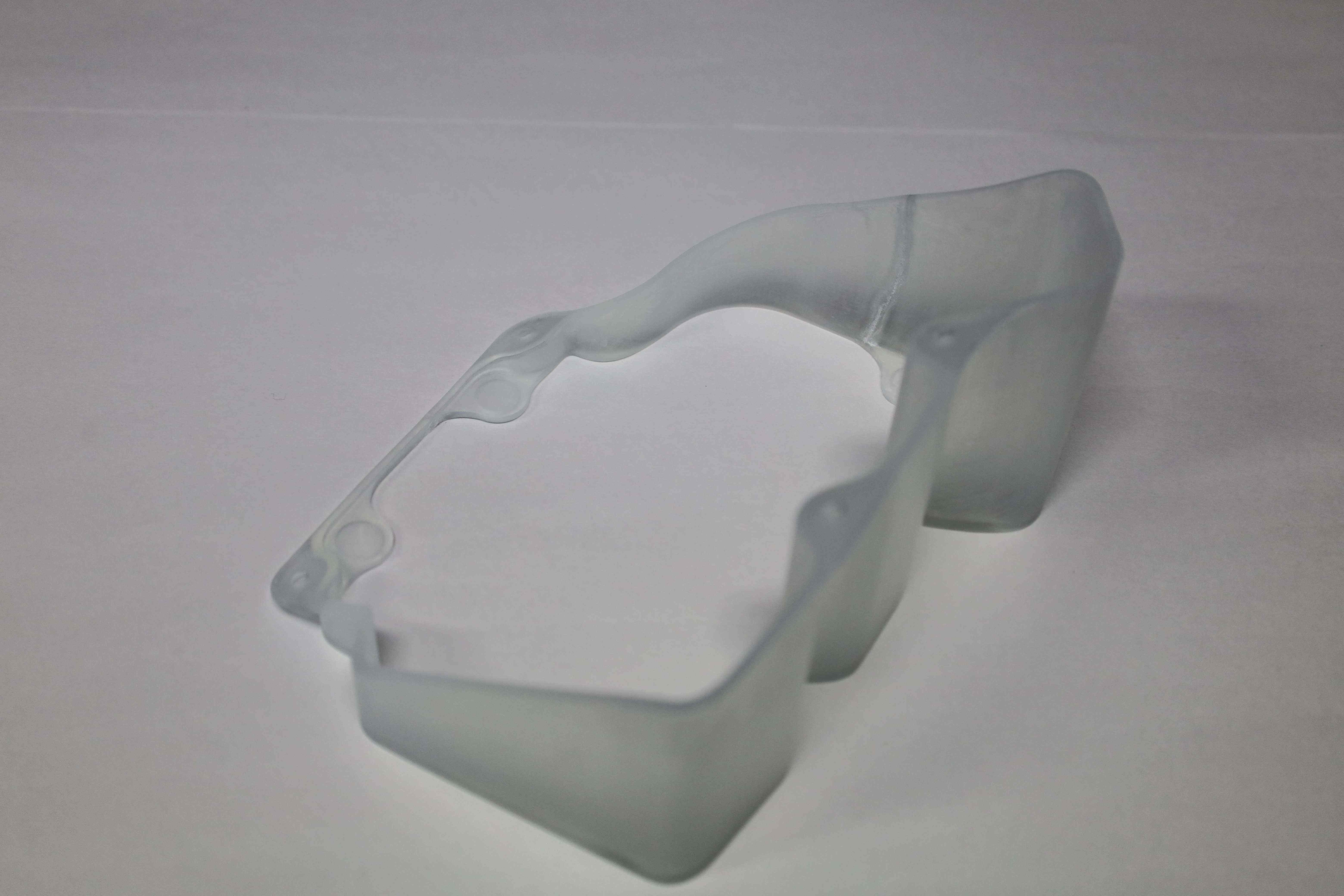
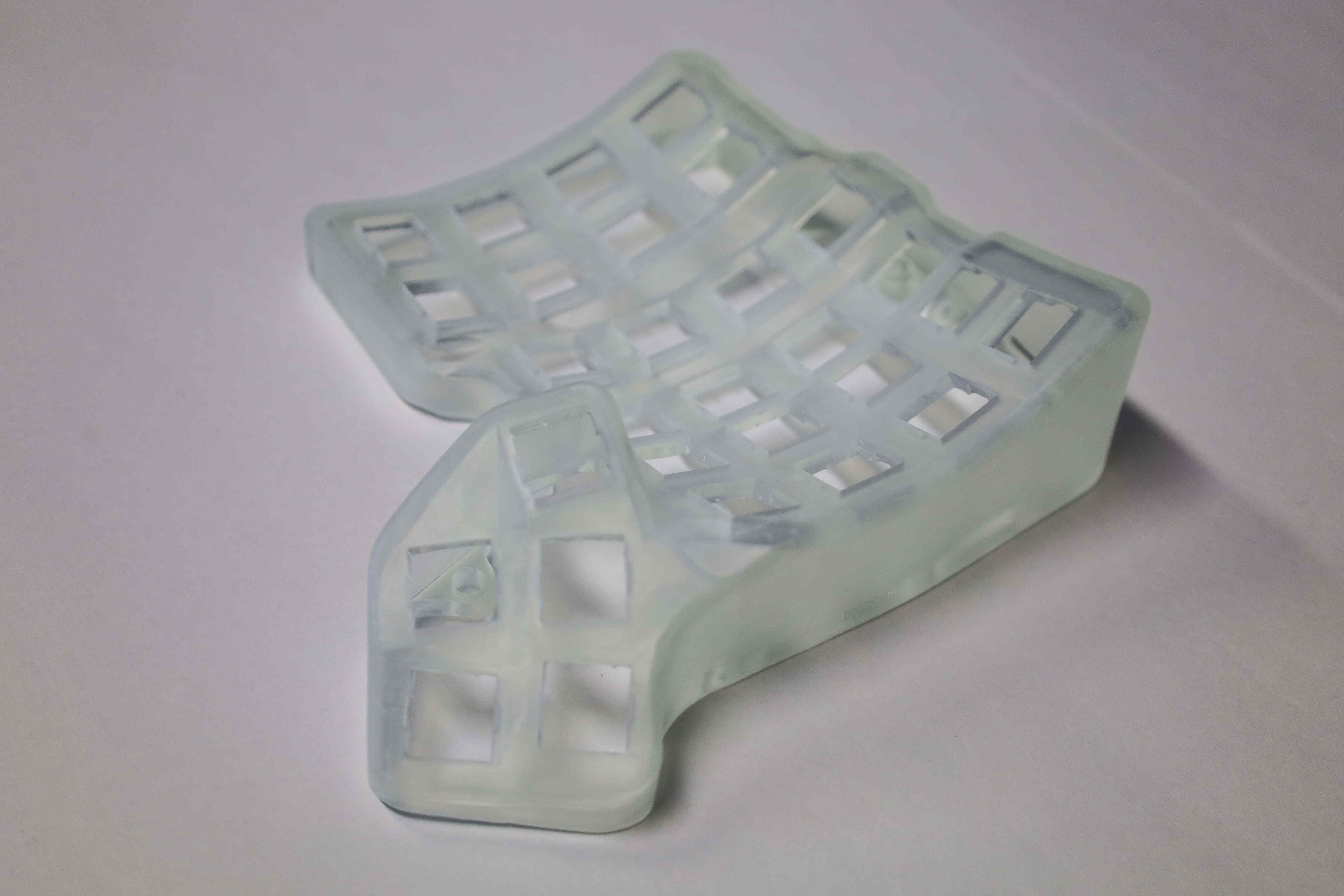
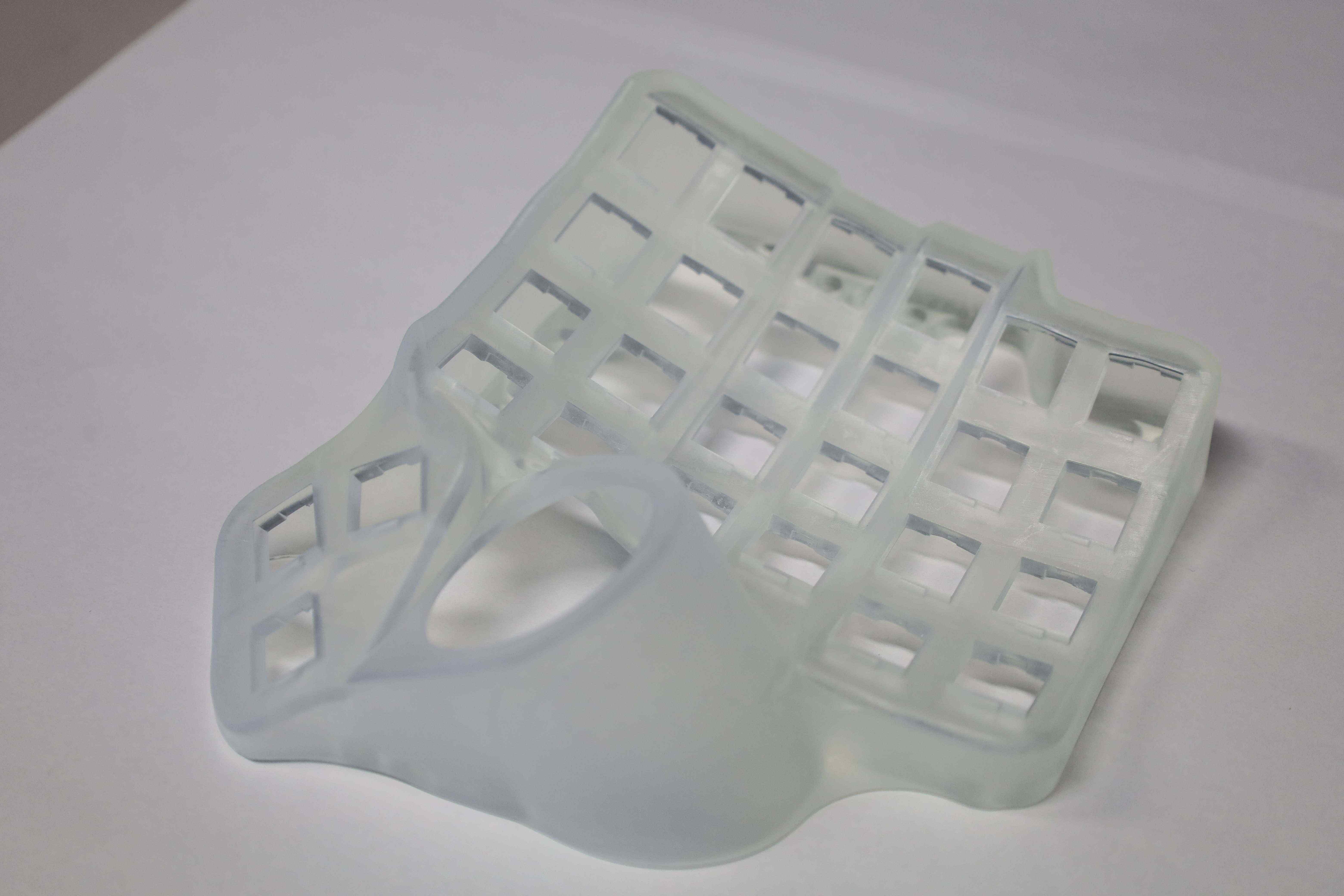
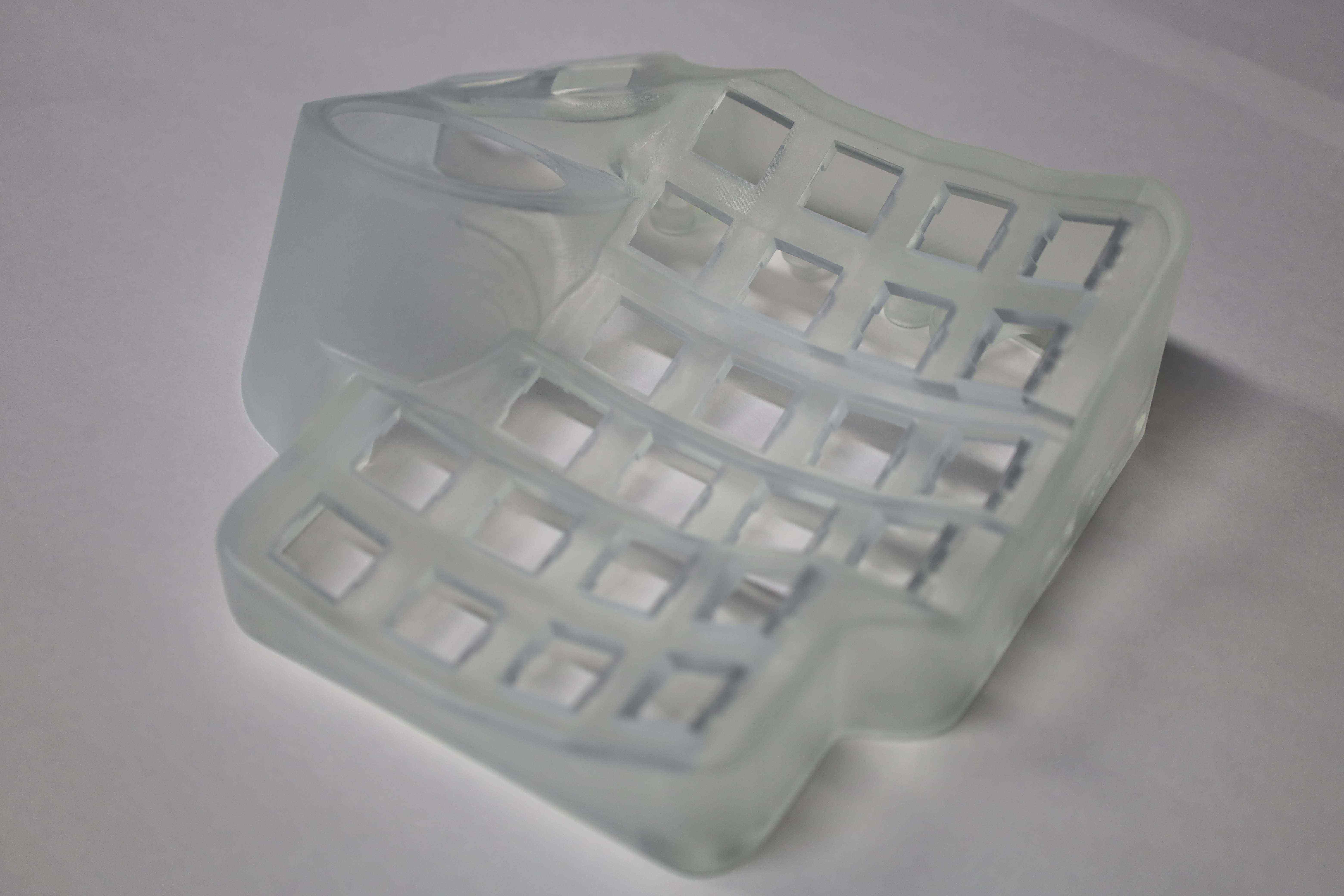
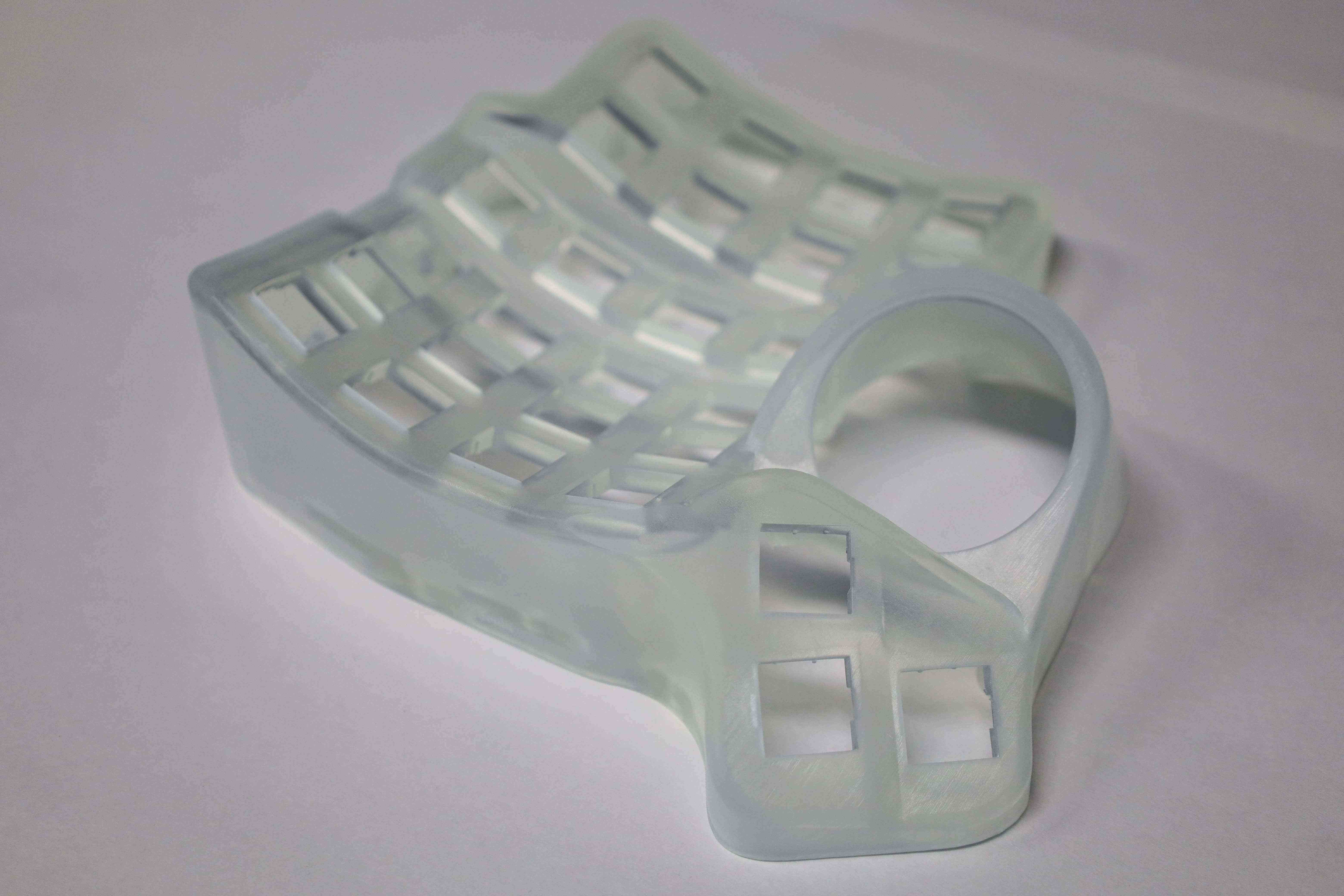
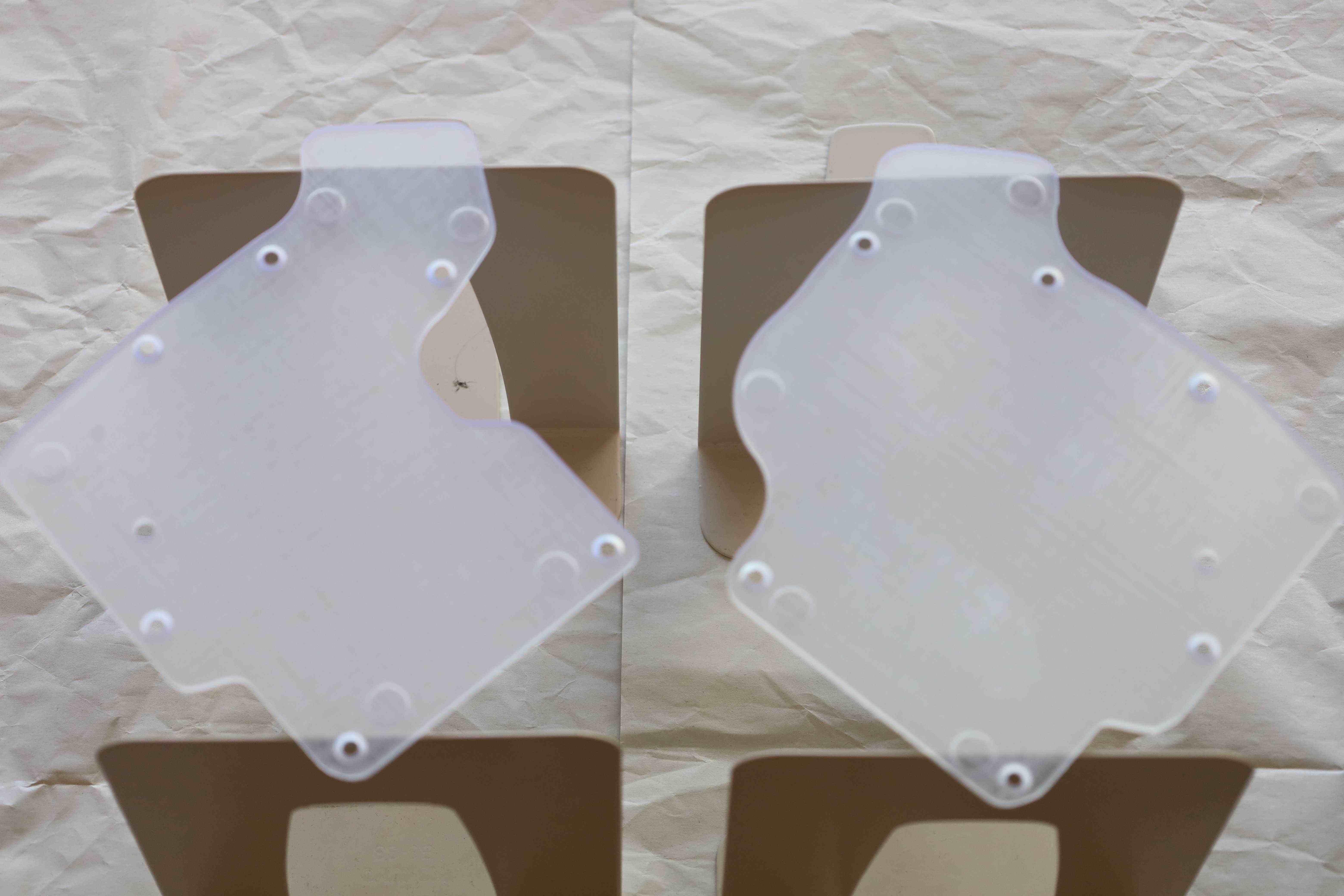
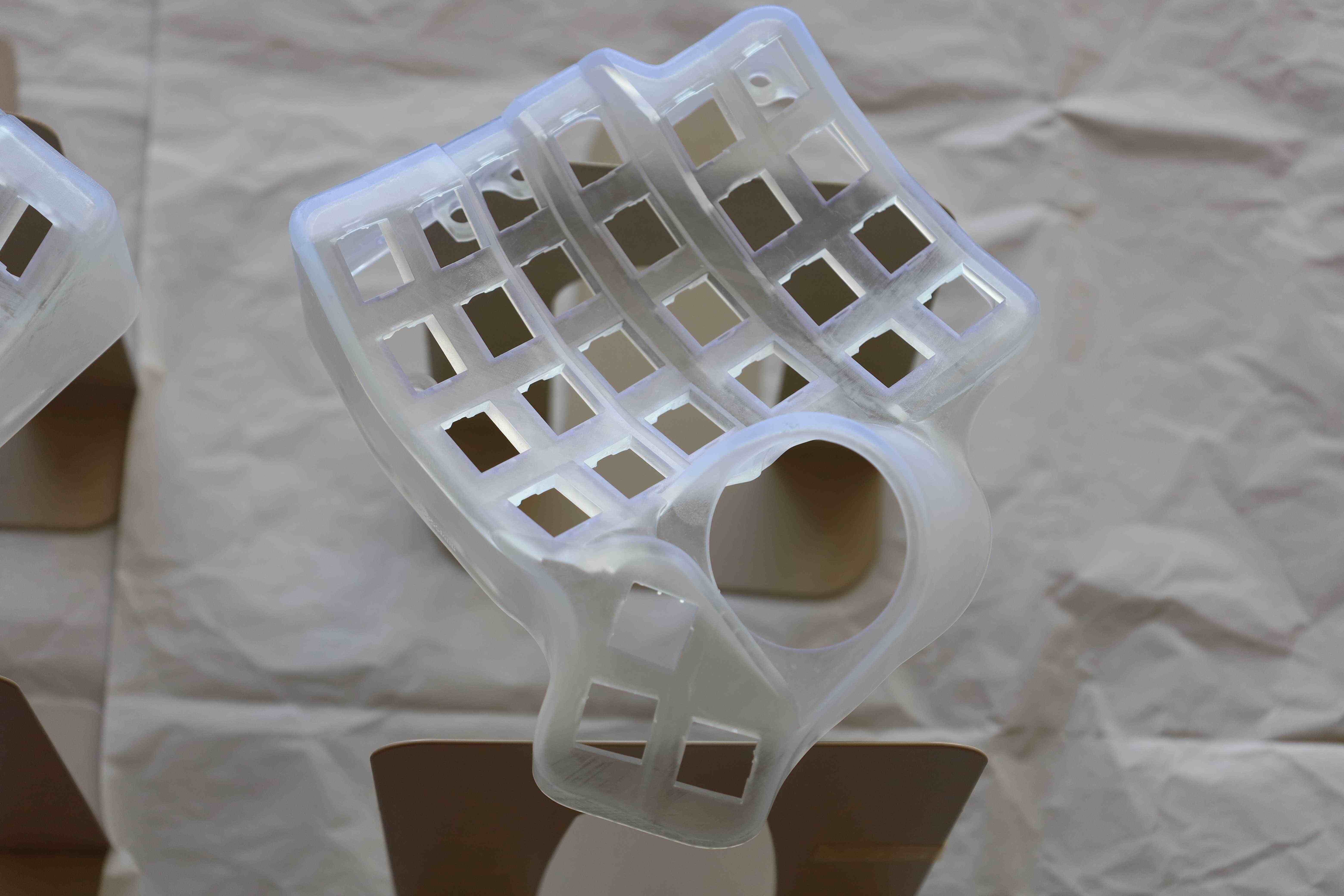
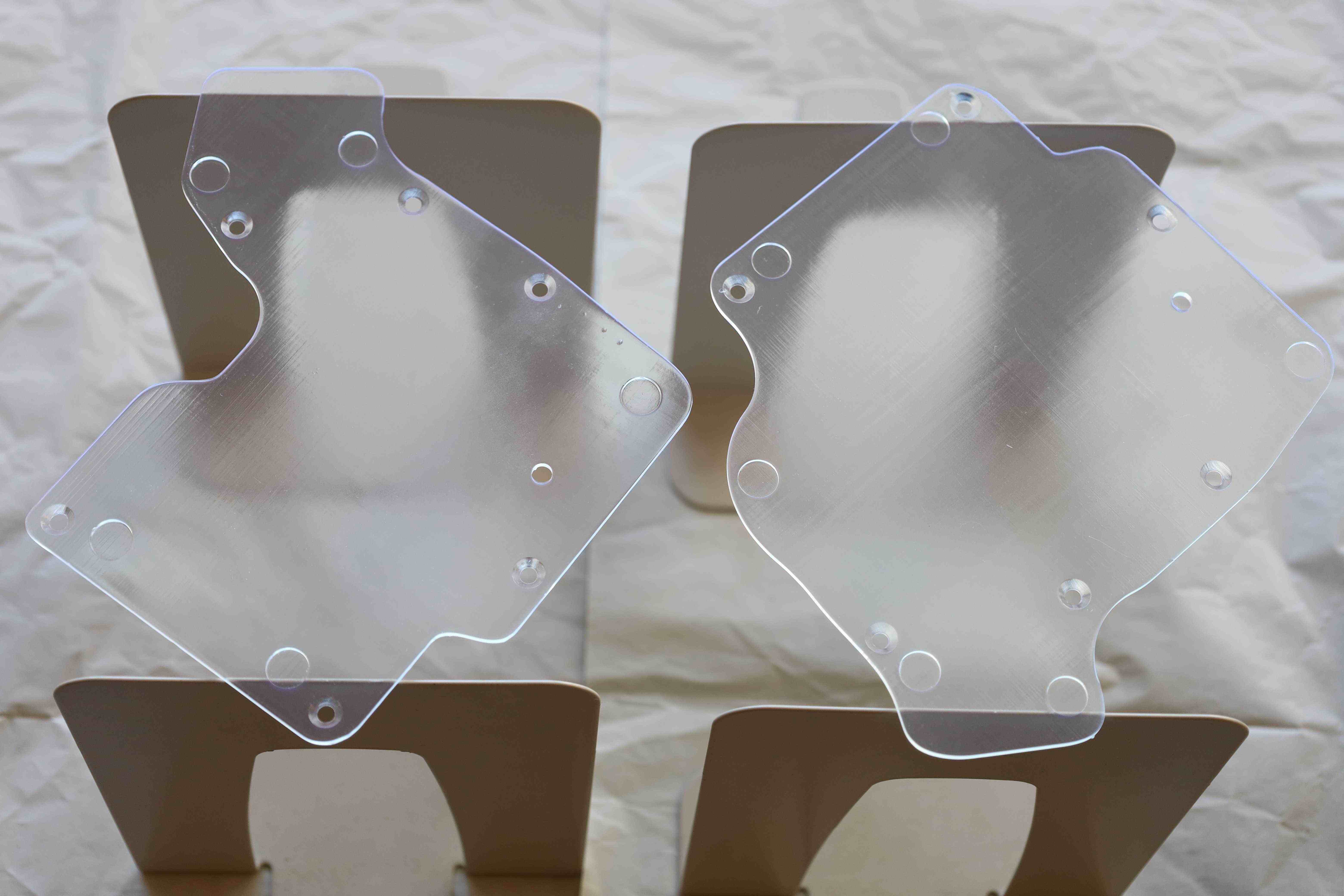
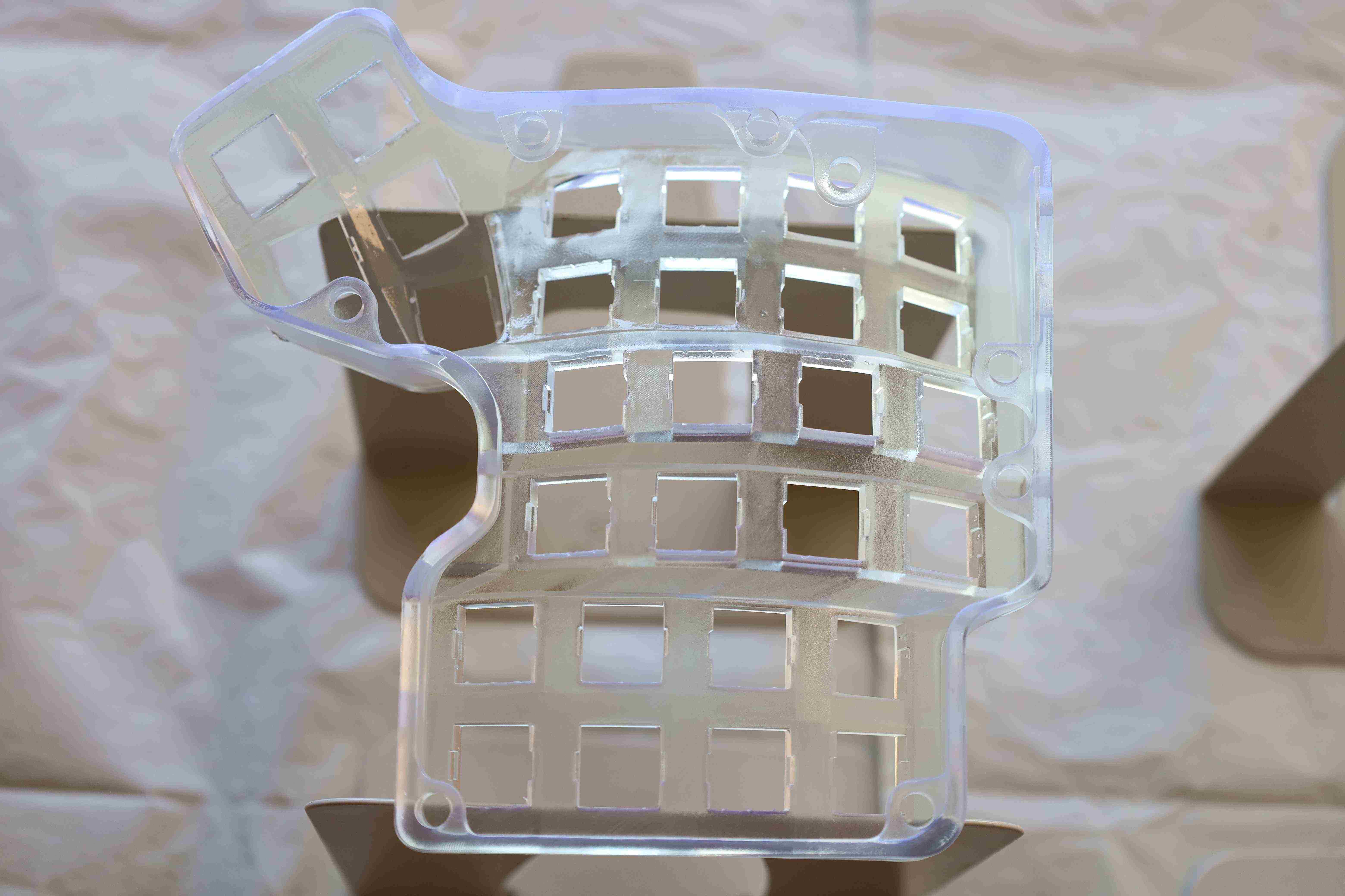
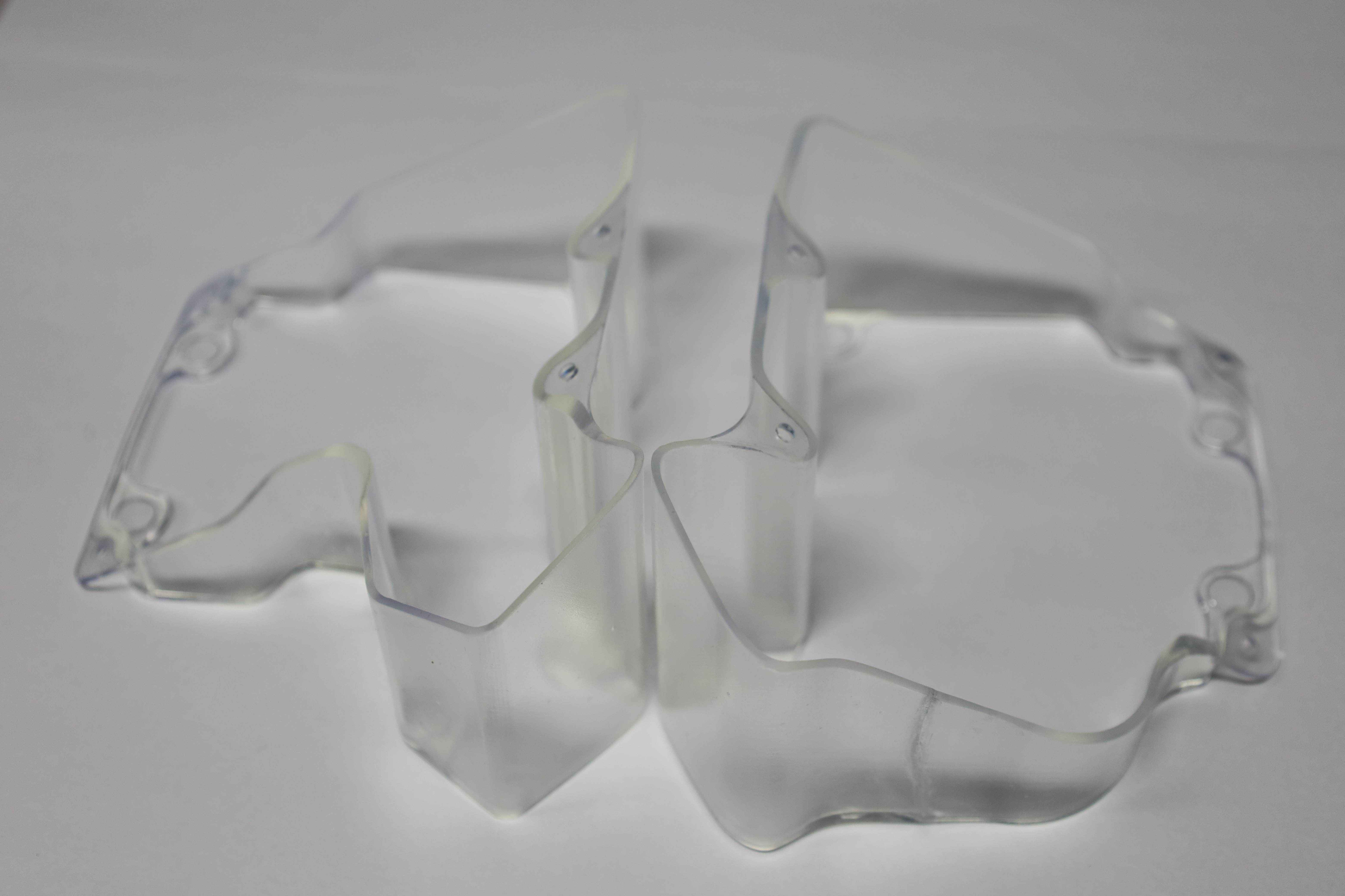
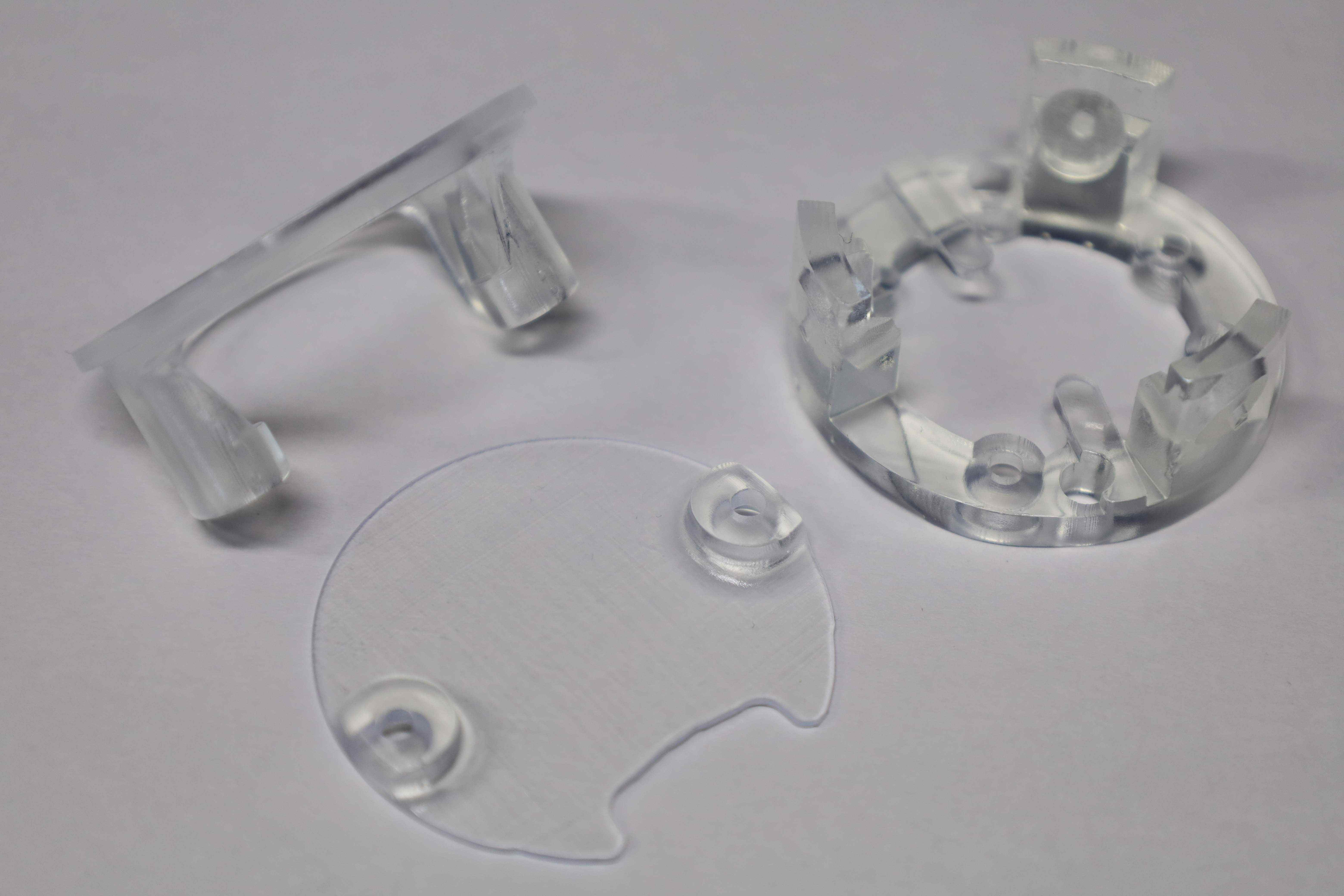
Finally, a small showcase of the 3D printing tool and process.
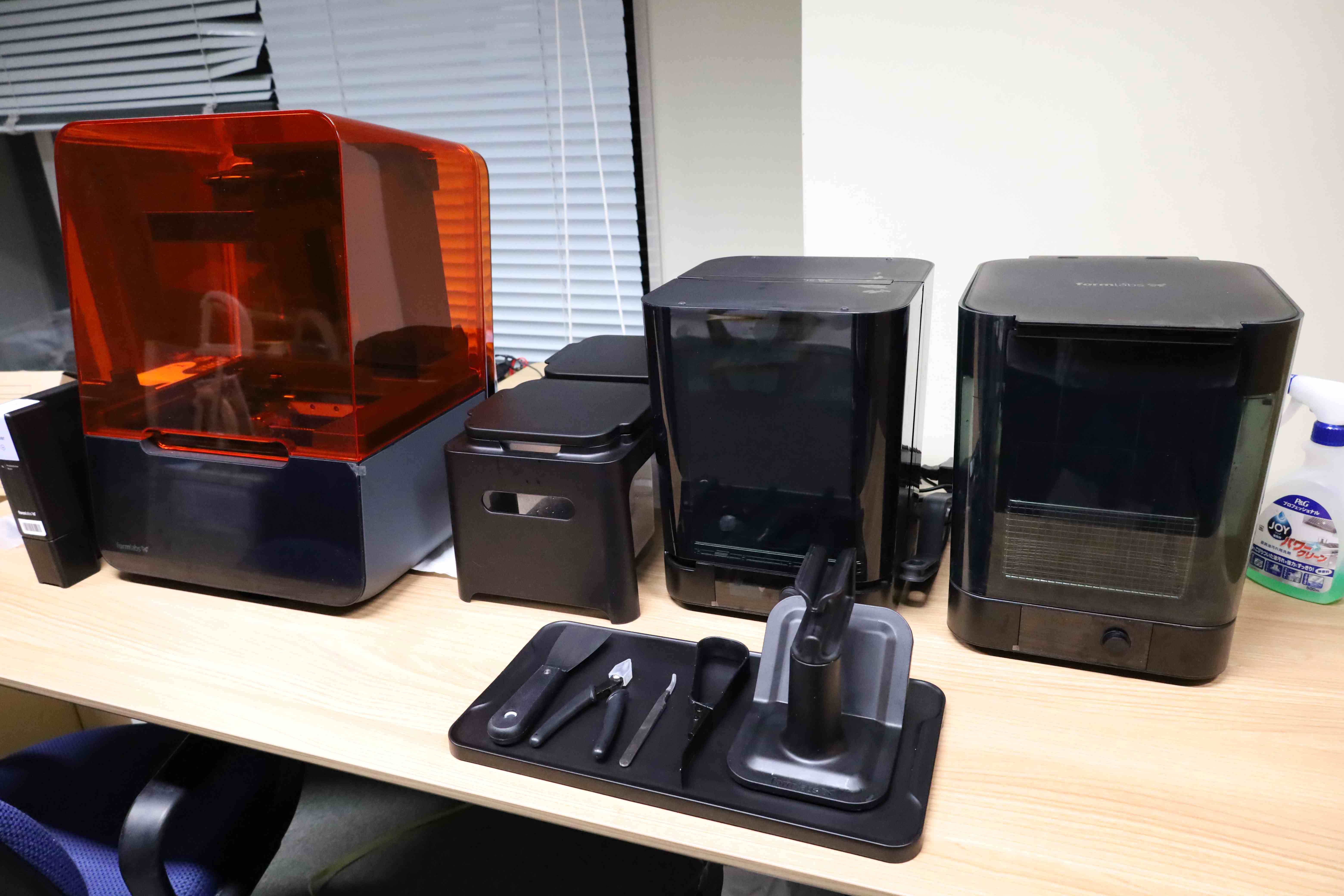


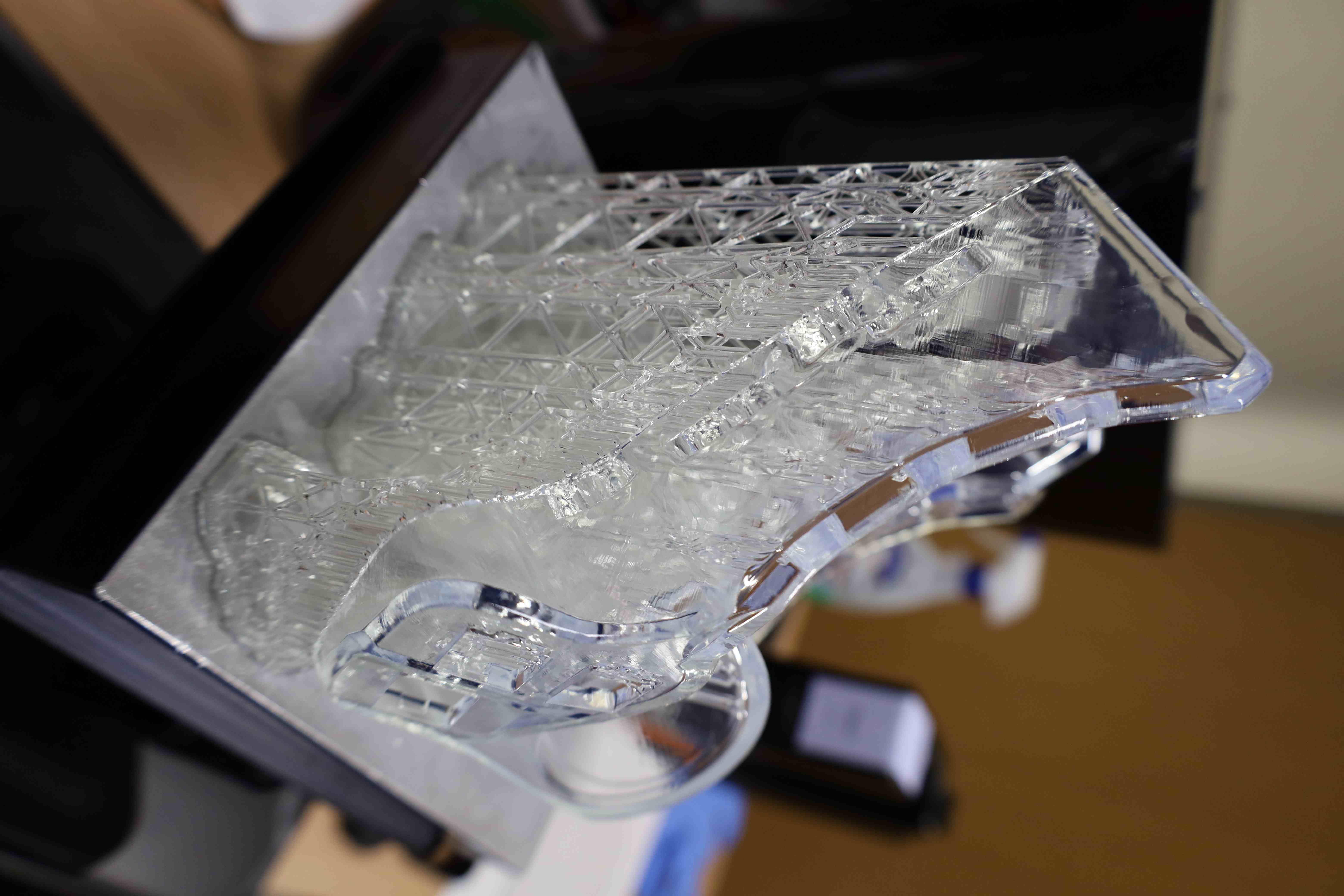

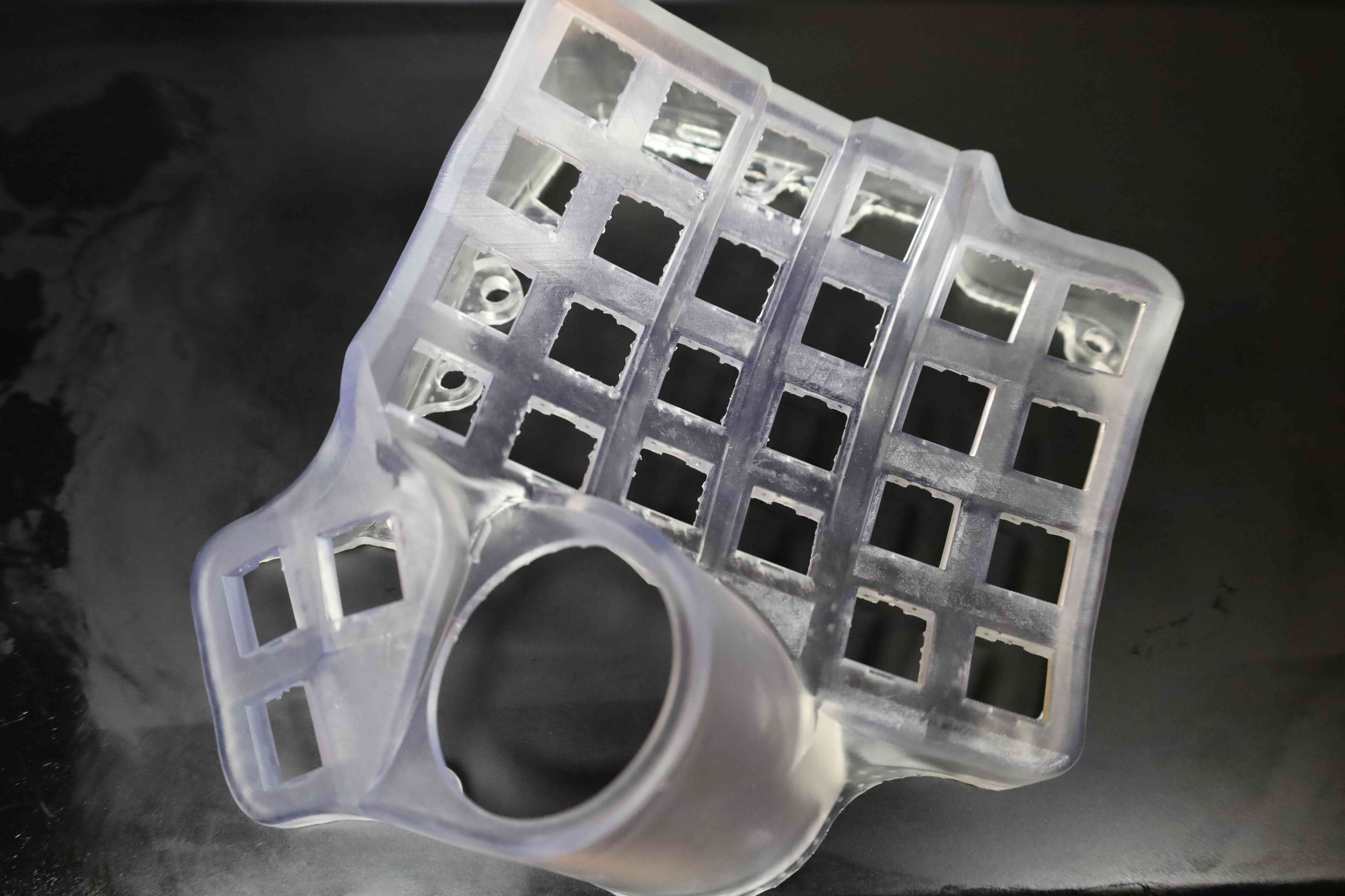
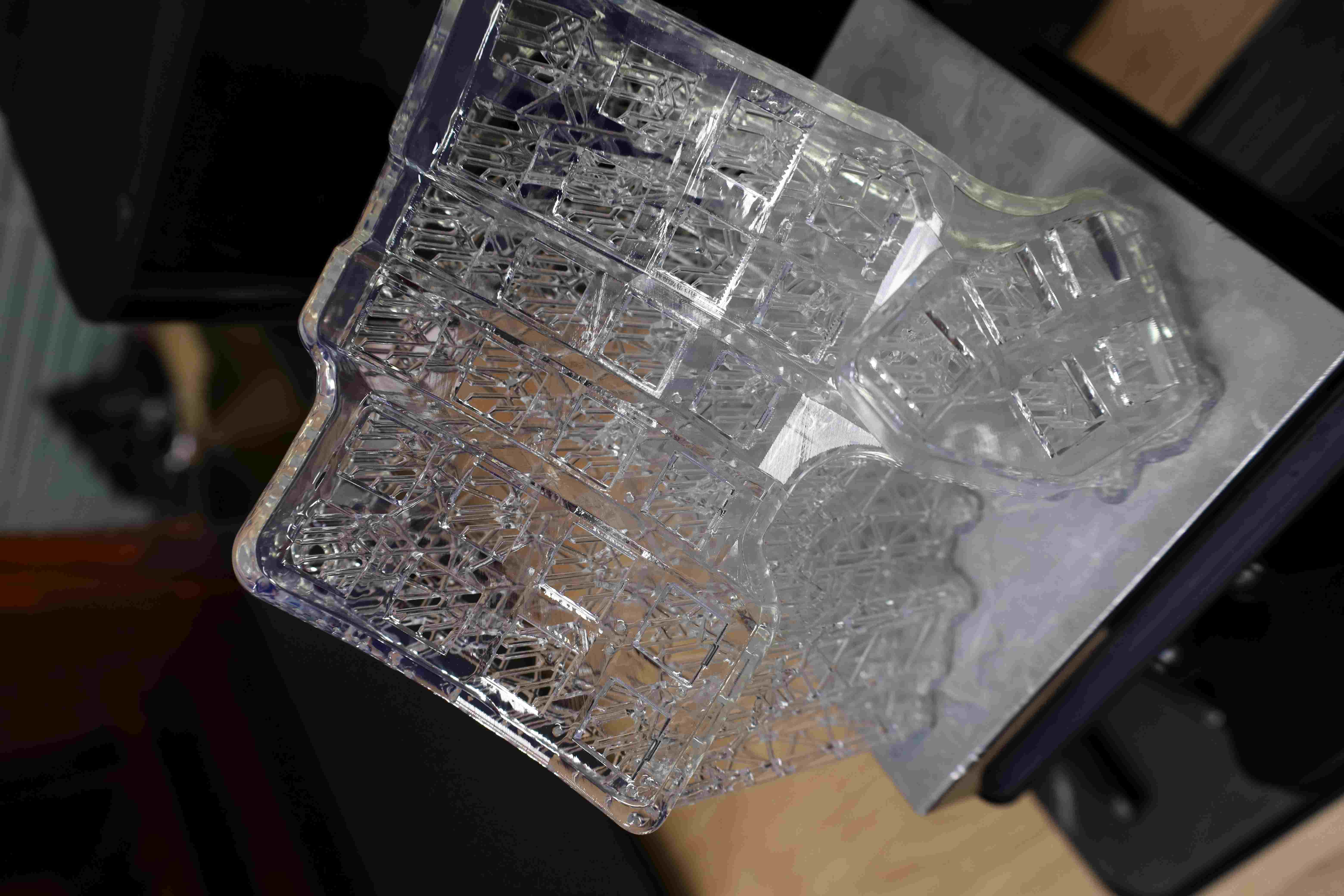
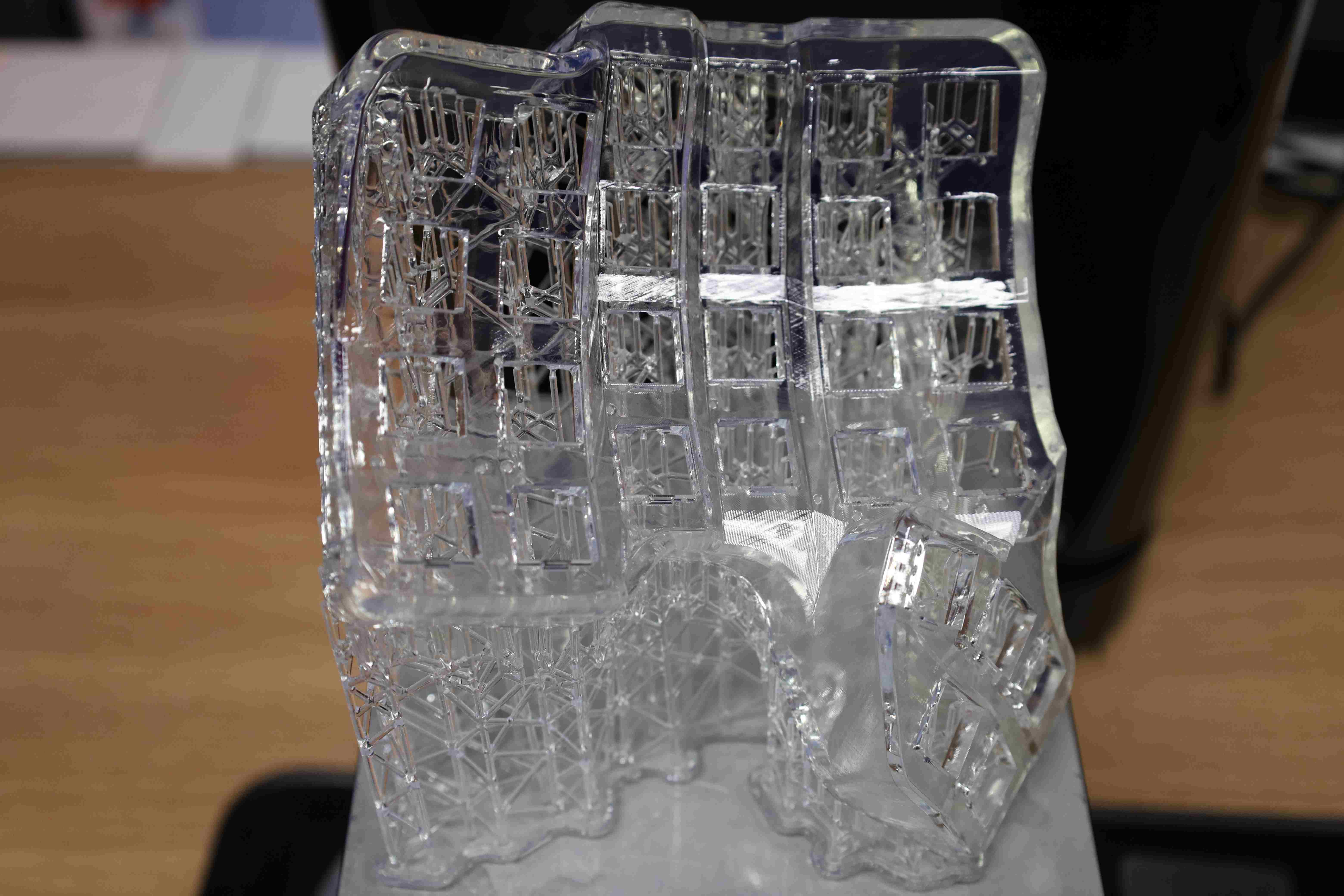
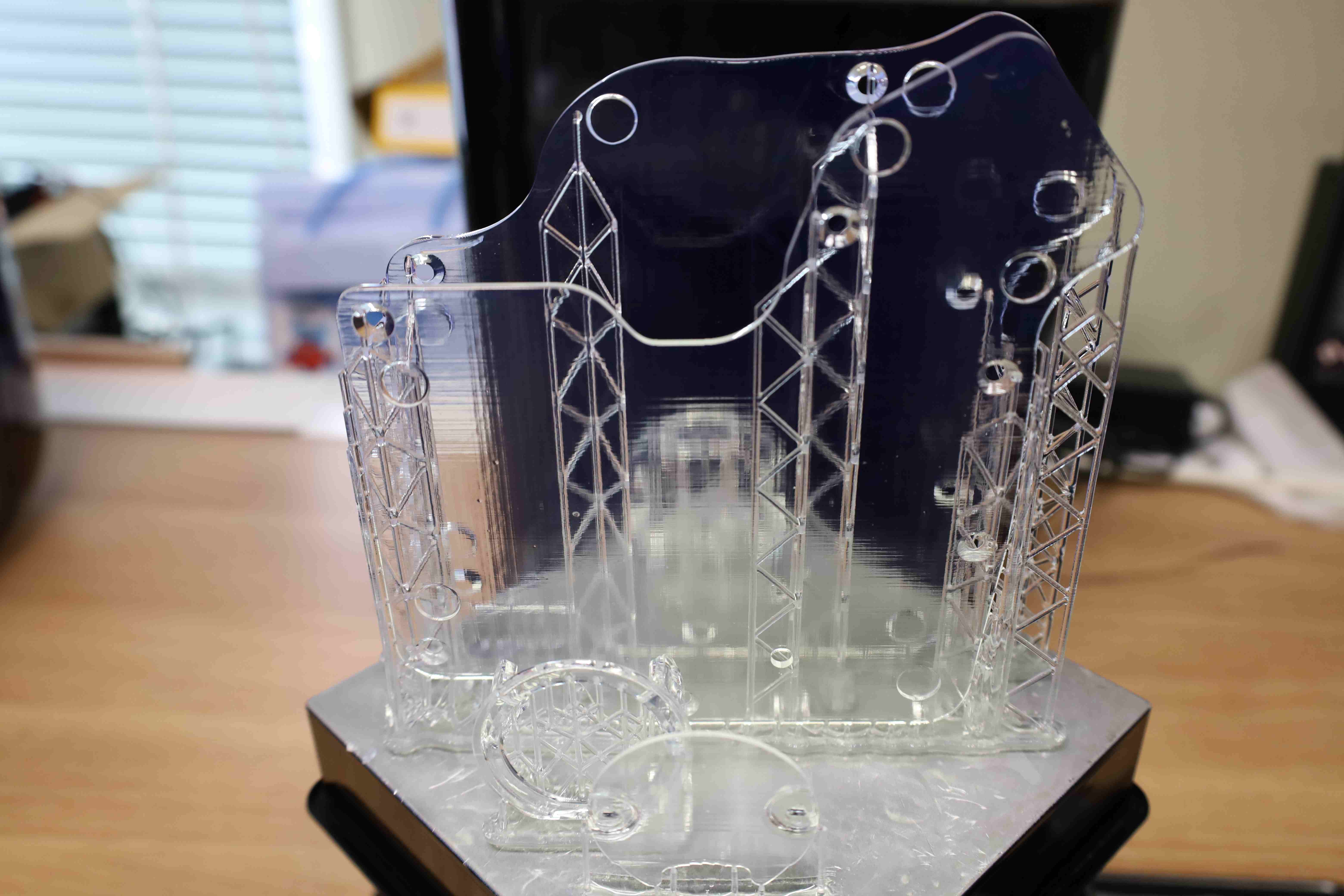

A quick note regarding printing such a wrist rest that has infills. Contrary to what is shown in the three pictures above, it is better to print objects that have such kind of holes or infills with the flat part facing the printing state. Namely, with the wrist rest as above, the removal of the supports after printing is inconvenient and is bound to leave some traces that would not see well with other mildly OCD fellows.
In subsequent print, it was easier to orient the 3D model with the flat face parallel to the printing stage, and the supports connecting directly to it. This makes the support removal easier, and their traces can be easily polished away. This also leaves the infill holes nice and clean, without scratches that would happen if the supports were set in those holes instead.
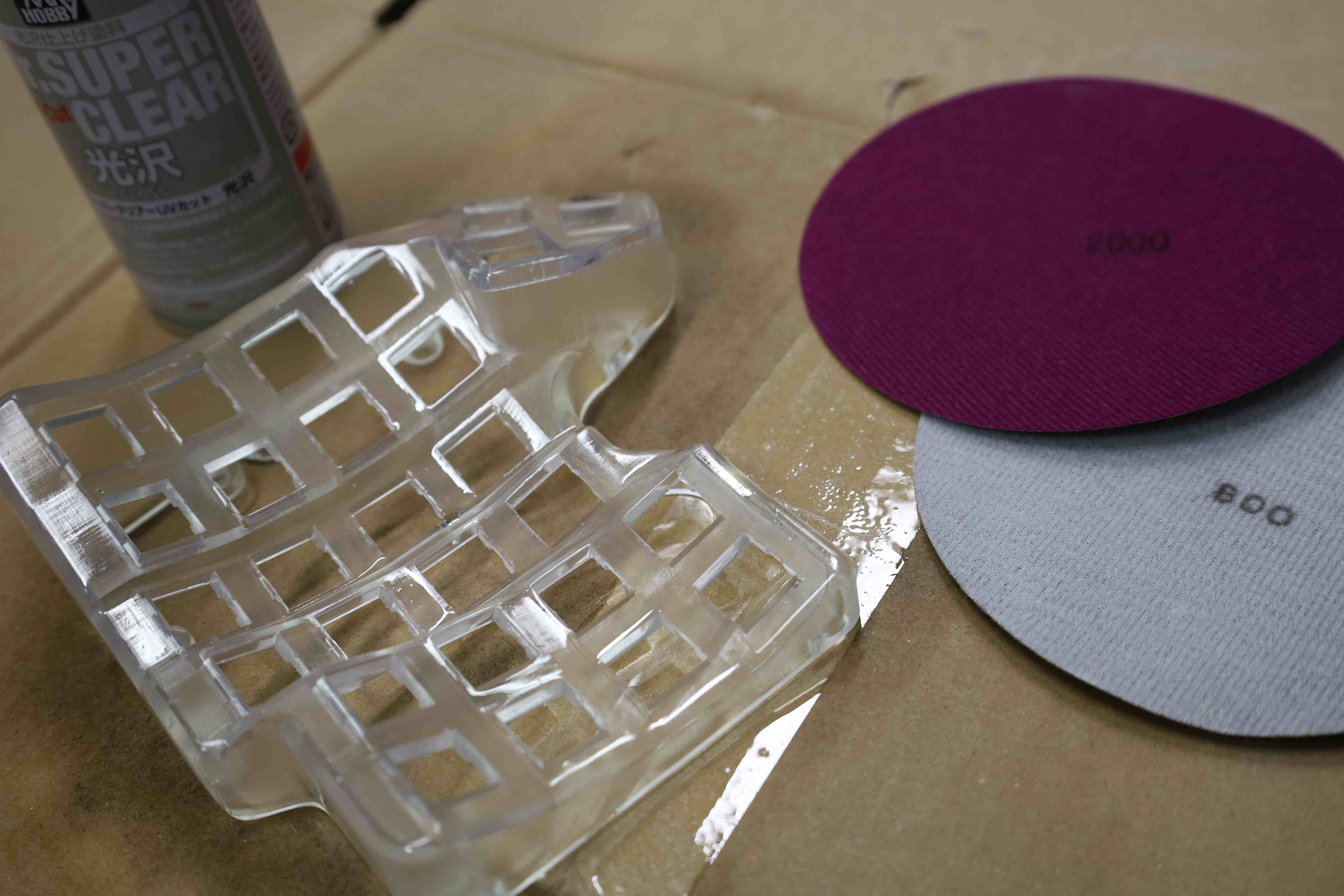
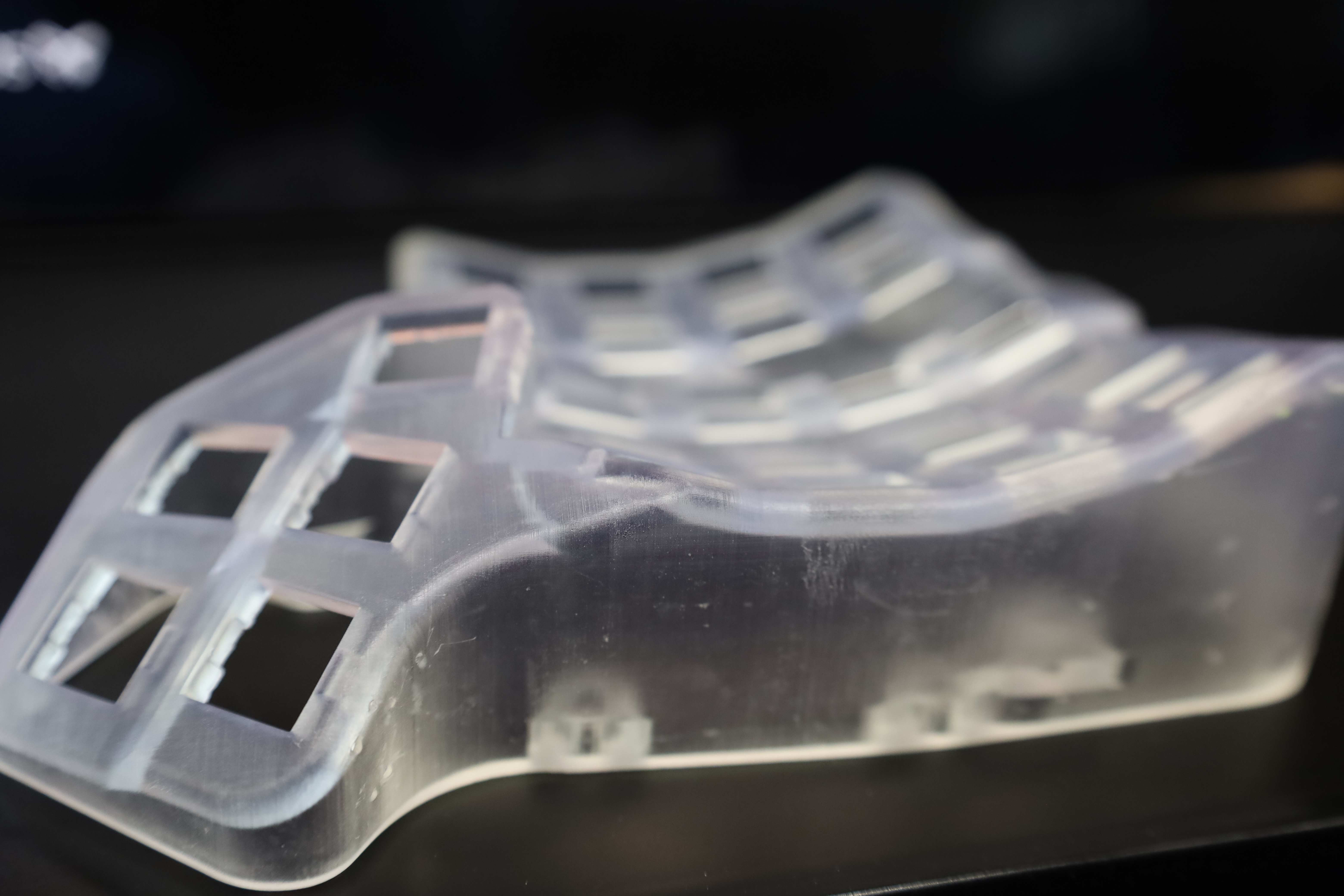
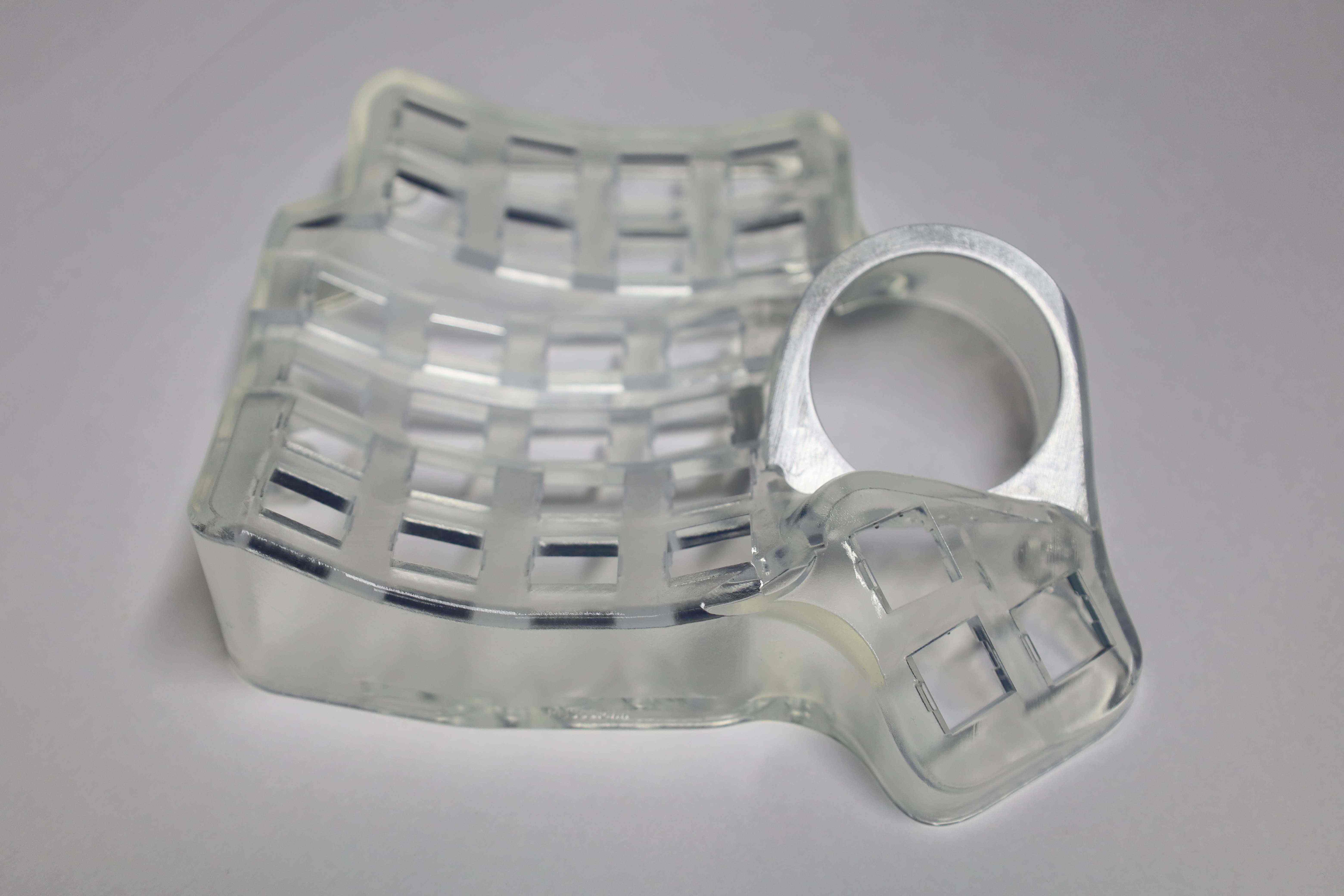
Unline FDM-based (filament) prints, resin prints would require some serious clean-up at least. In this case, where the case was printed from a clear/transparent resin, the post-processing not only requires careful and thorough cleaning, but also polishing, and even coating.
First, the case components were polished using sandpaper of roughness of $800$ then $2000$. Dry polish revealed itself to be quite uncomfortable both to the touch, sight, and the ears (like bad chalk screeching on a blackboard). Wet polishing, on the other hand, allows for better visibility of the remaining support while polishing, while making the overall process less irritative for the touch and the ears.


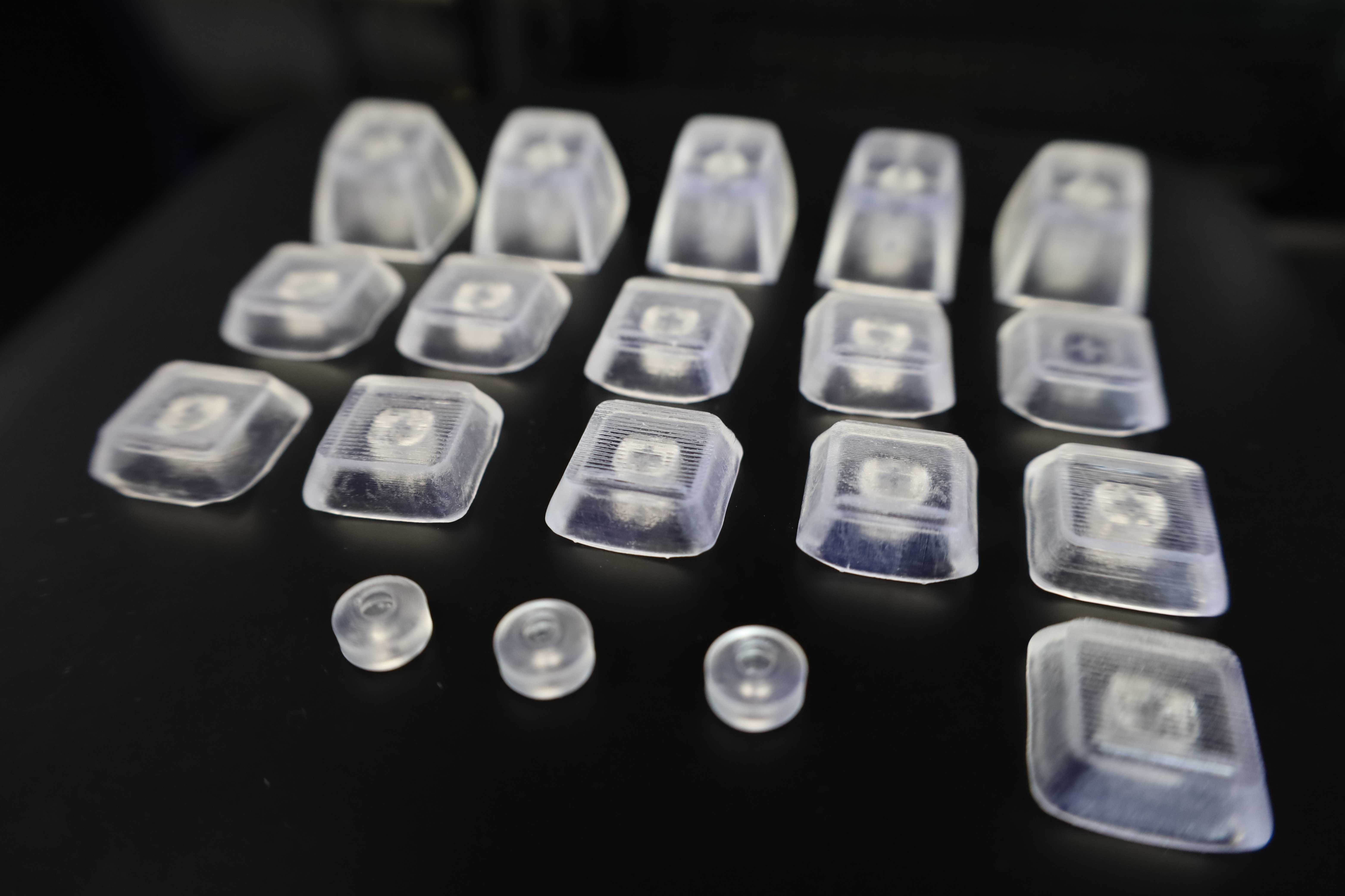
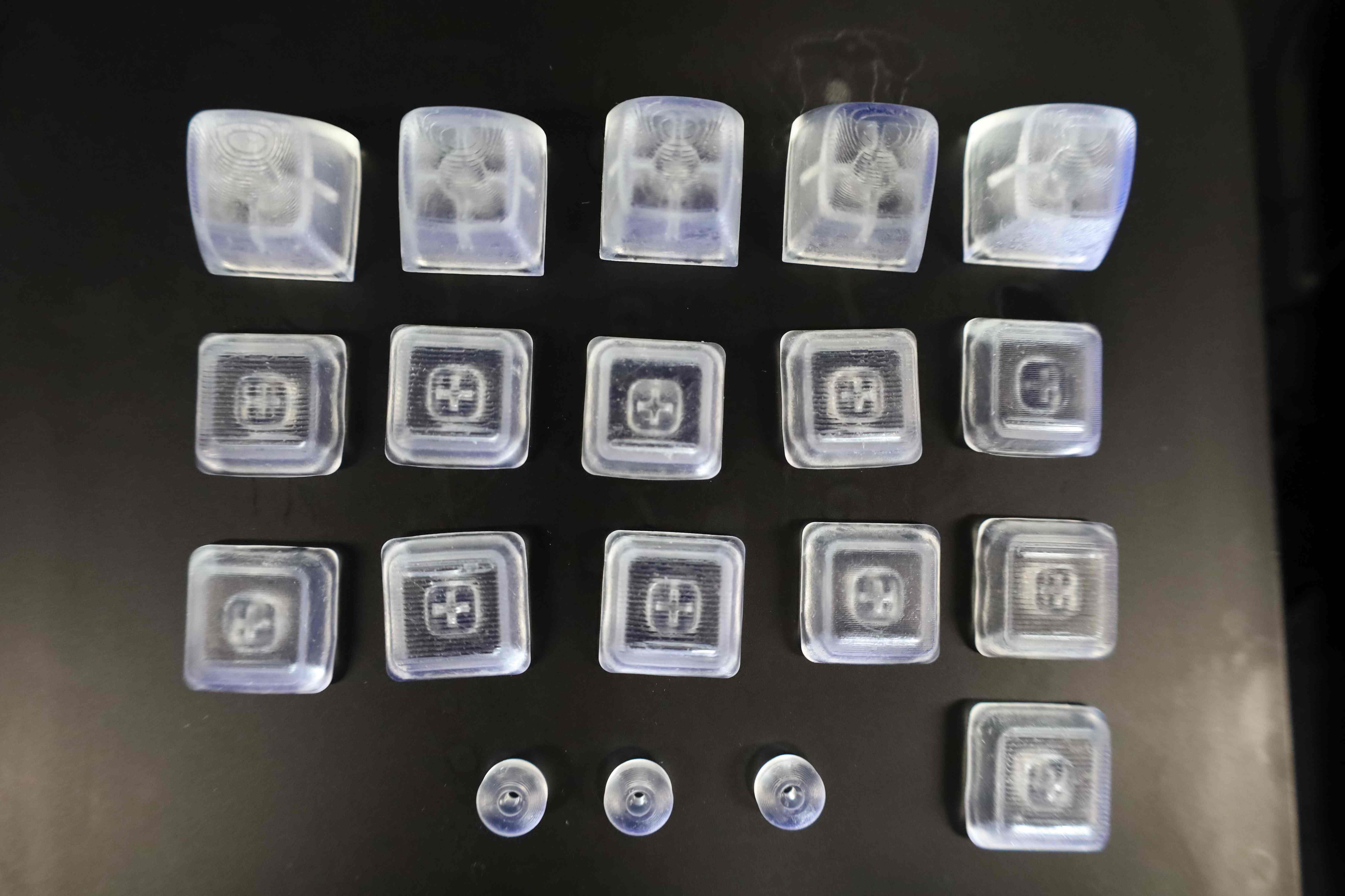
There was an attempt at printing custom keycaps. While usable, the results are not as good as a commercially available alternative. It might be caused by using the default layer width of $0.1$mm when printing, but there were visible lines that could be felt on the surface of the keys. While this detail could be polished away, it defeats the purpose if the key cap is expected to have a bump to serve as a landmark for the home row. The sharp edges of the keycaps would usually be botched during the printing too.
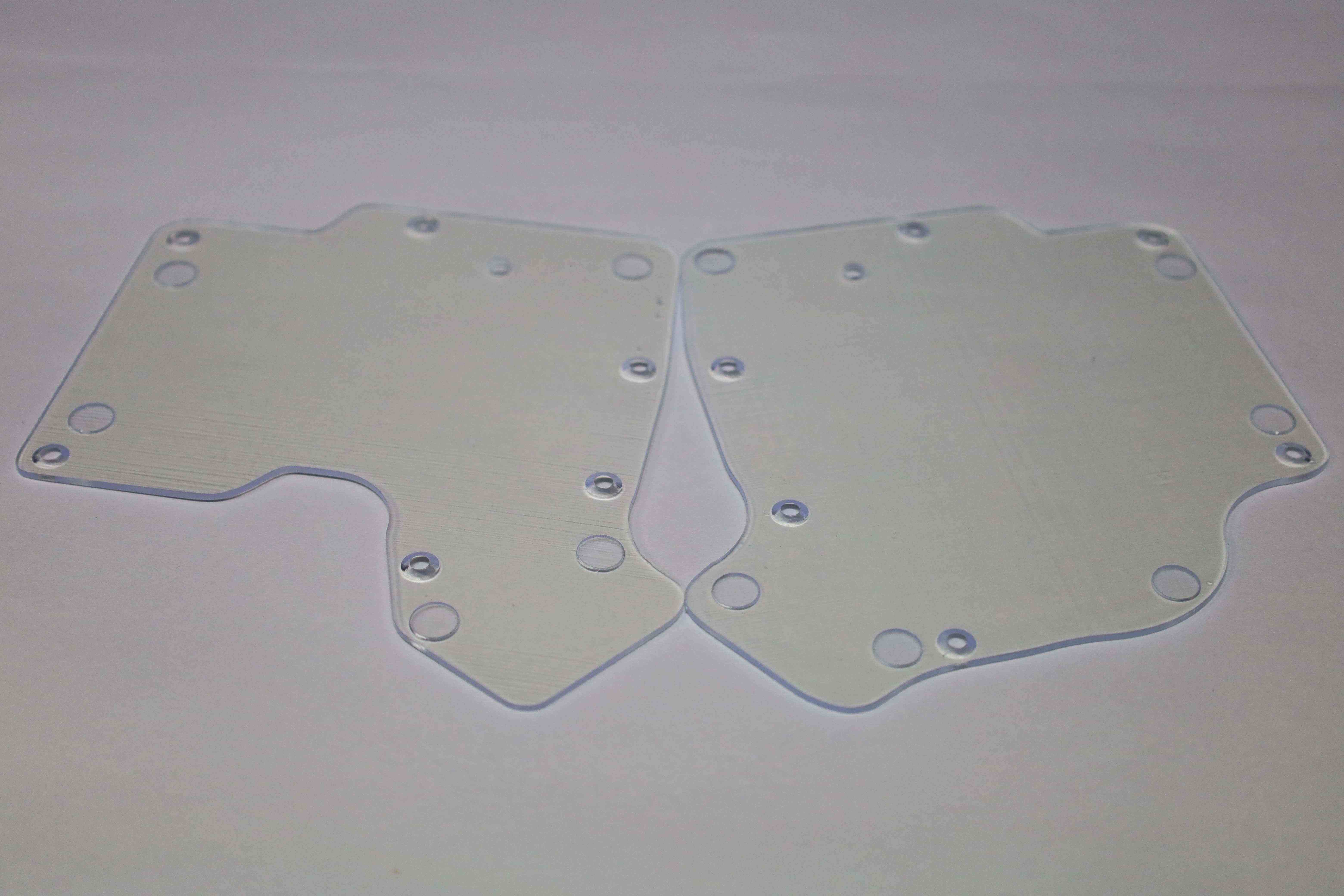
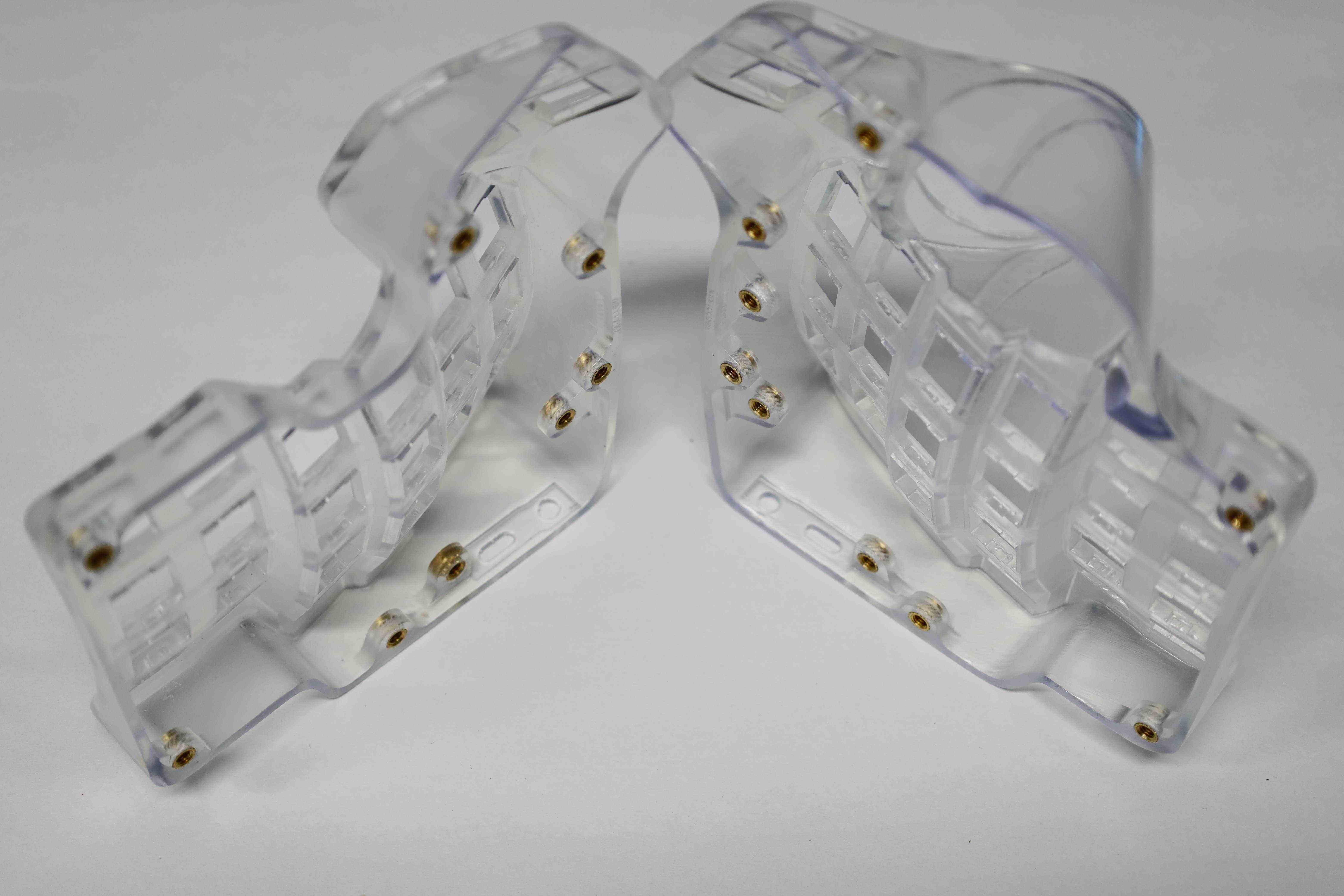
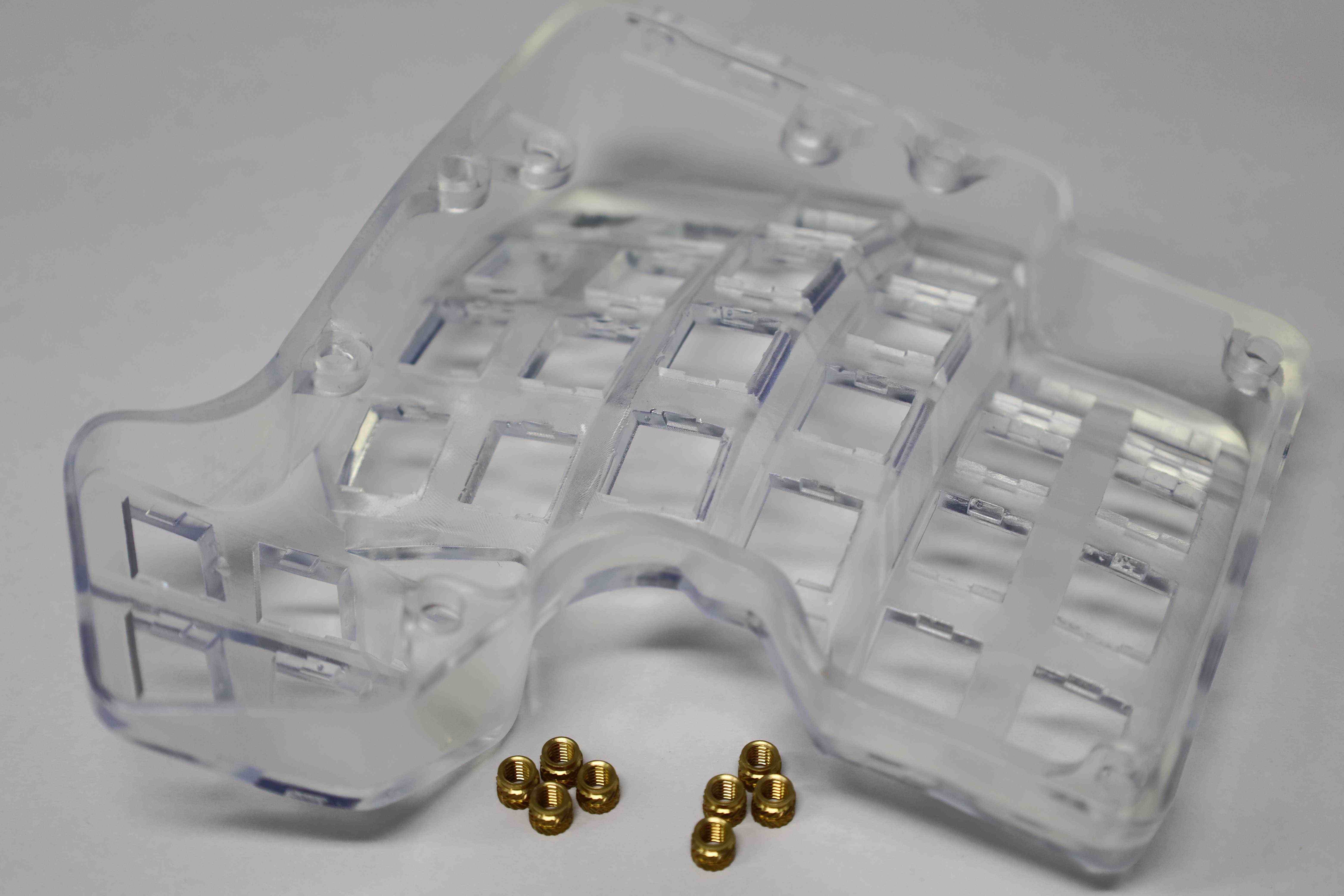
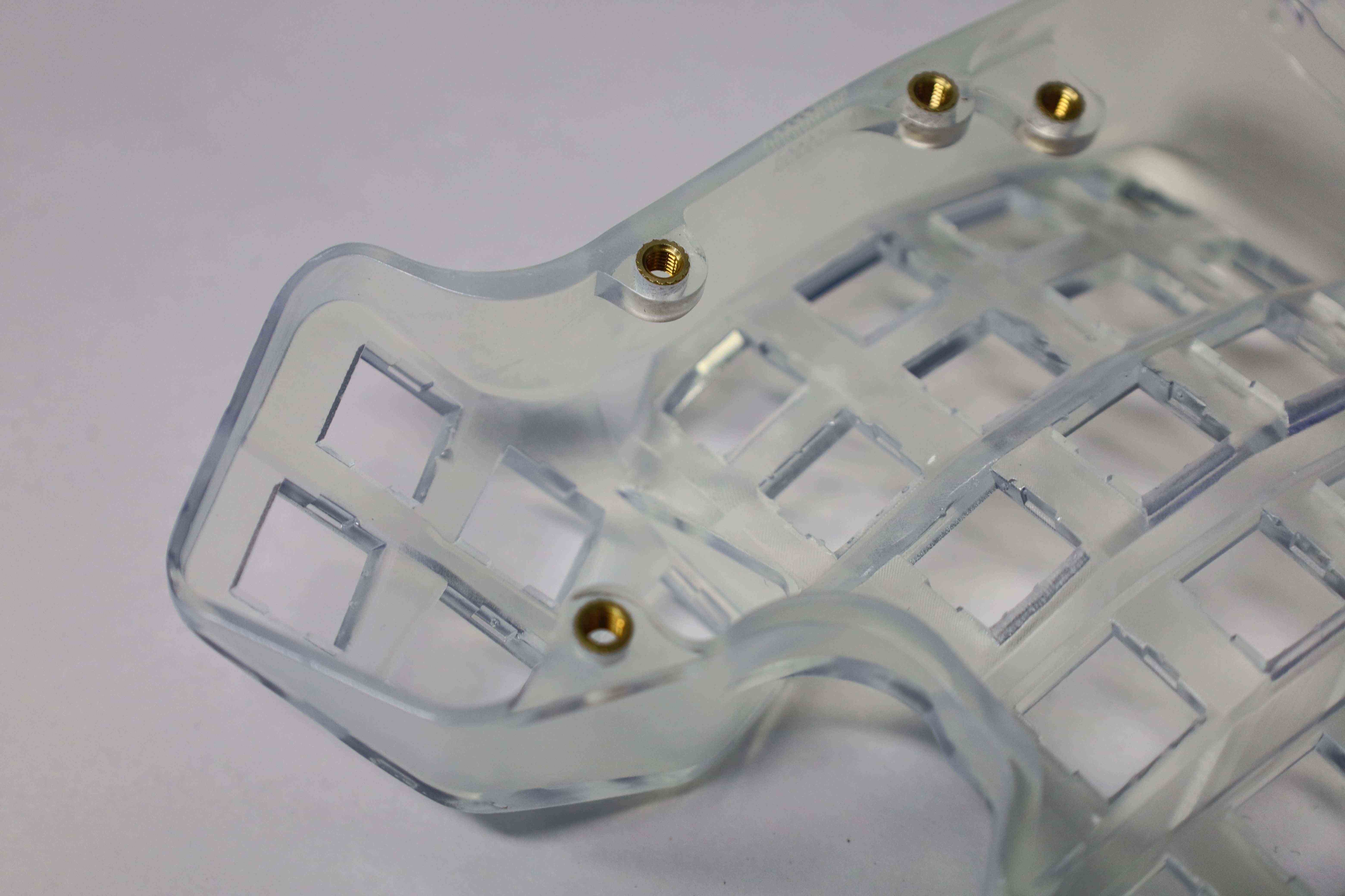
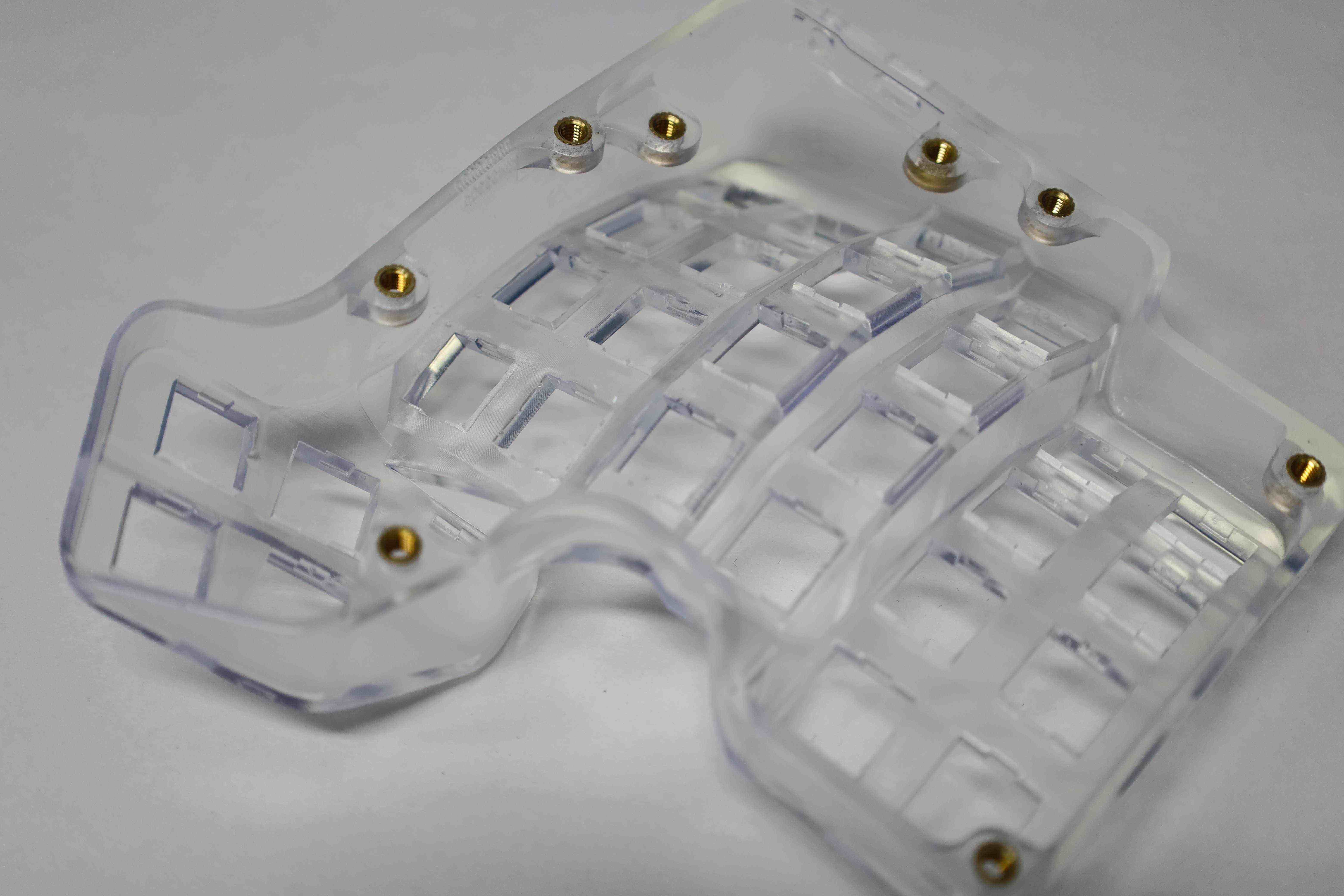
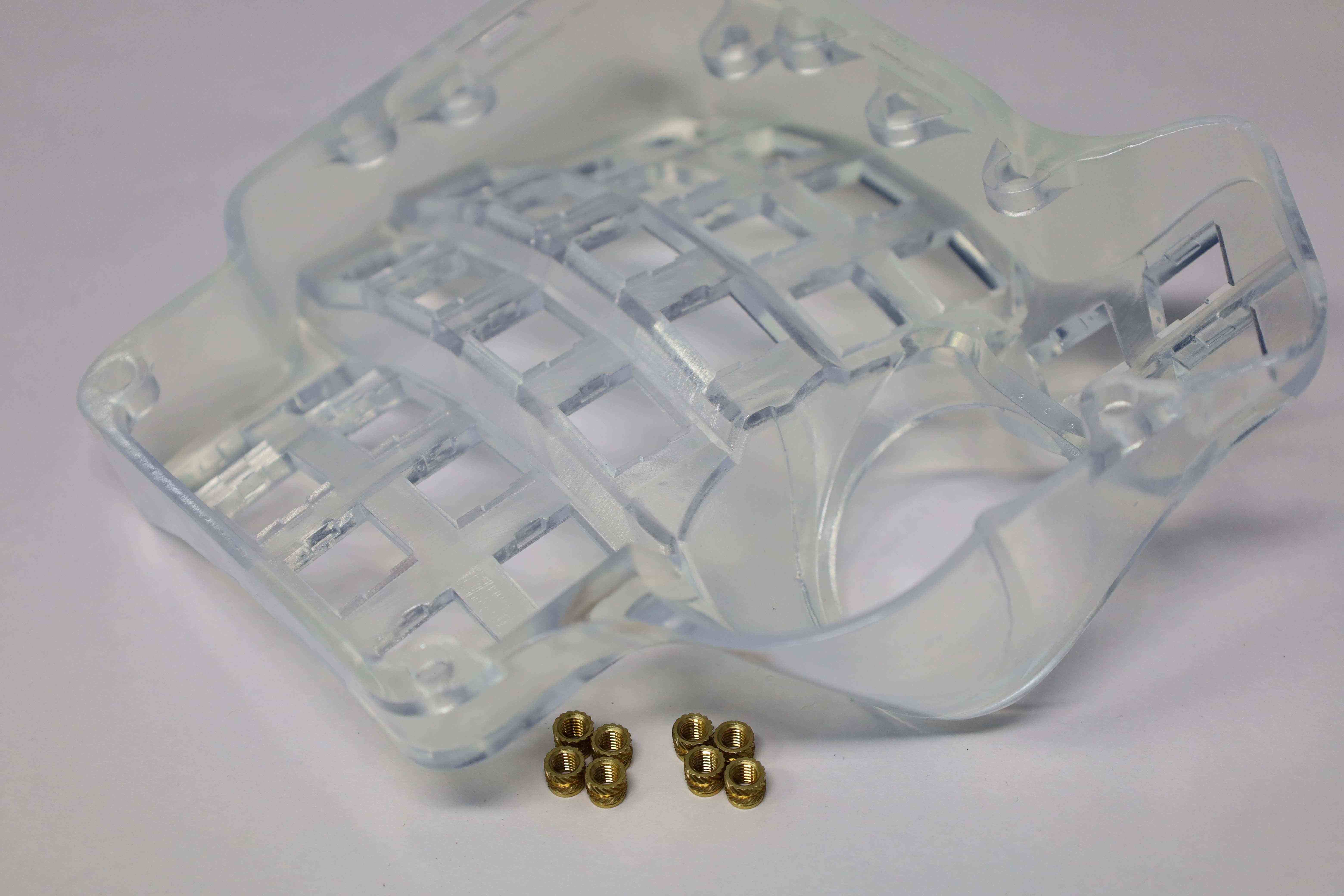
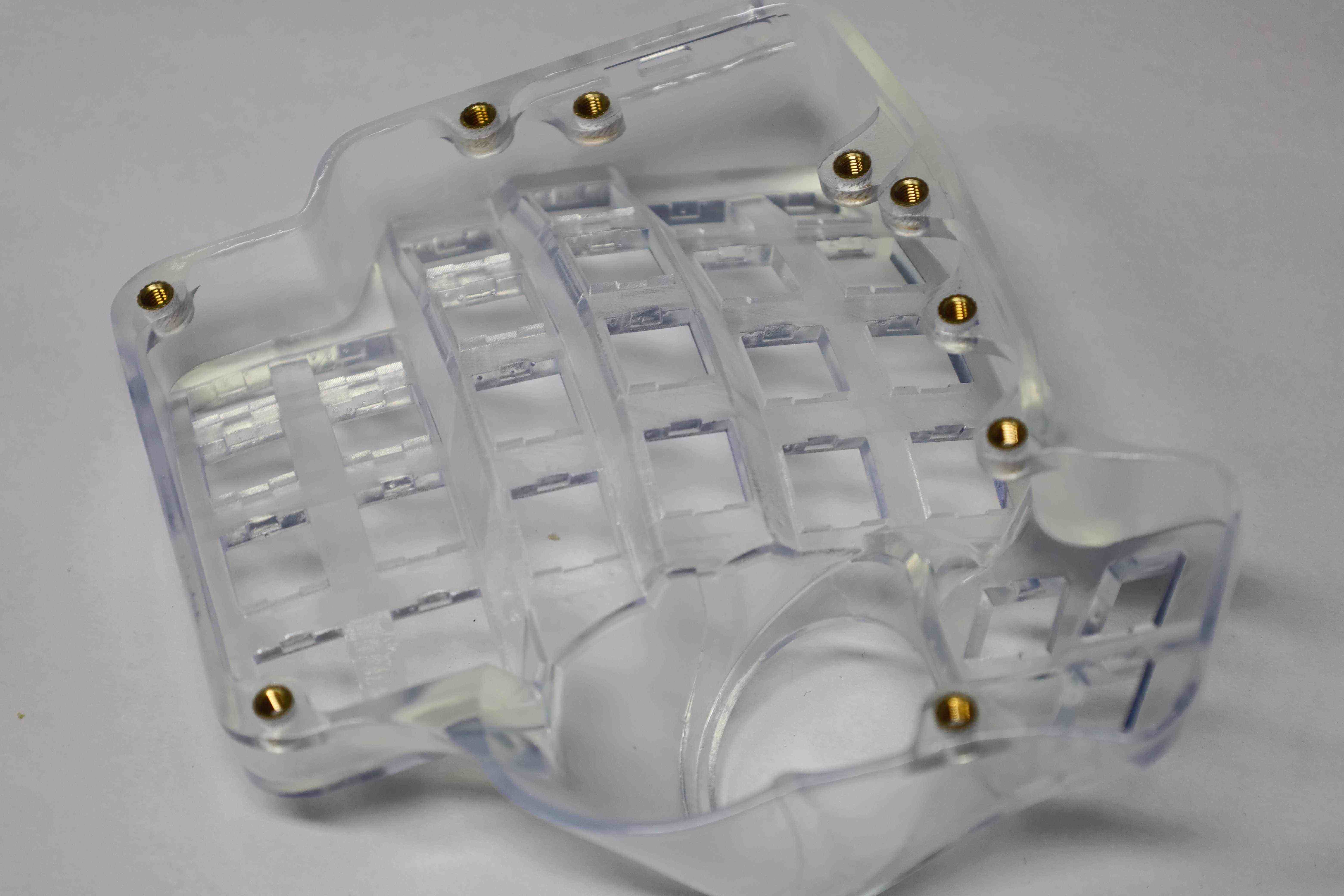
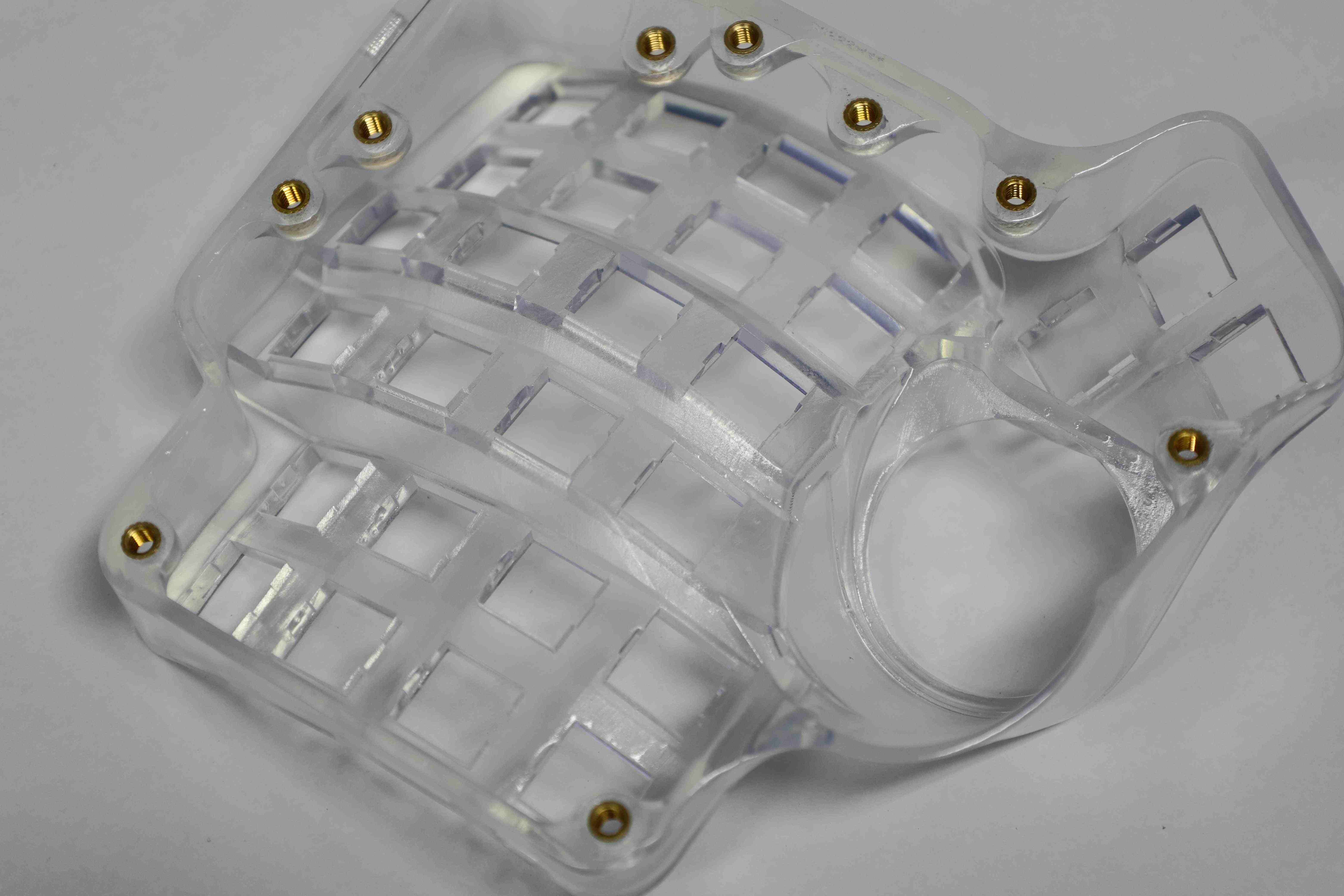
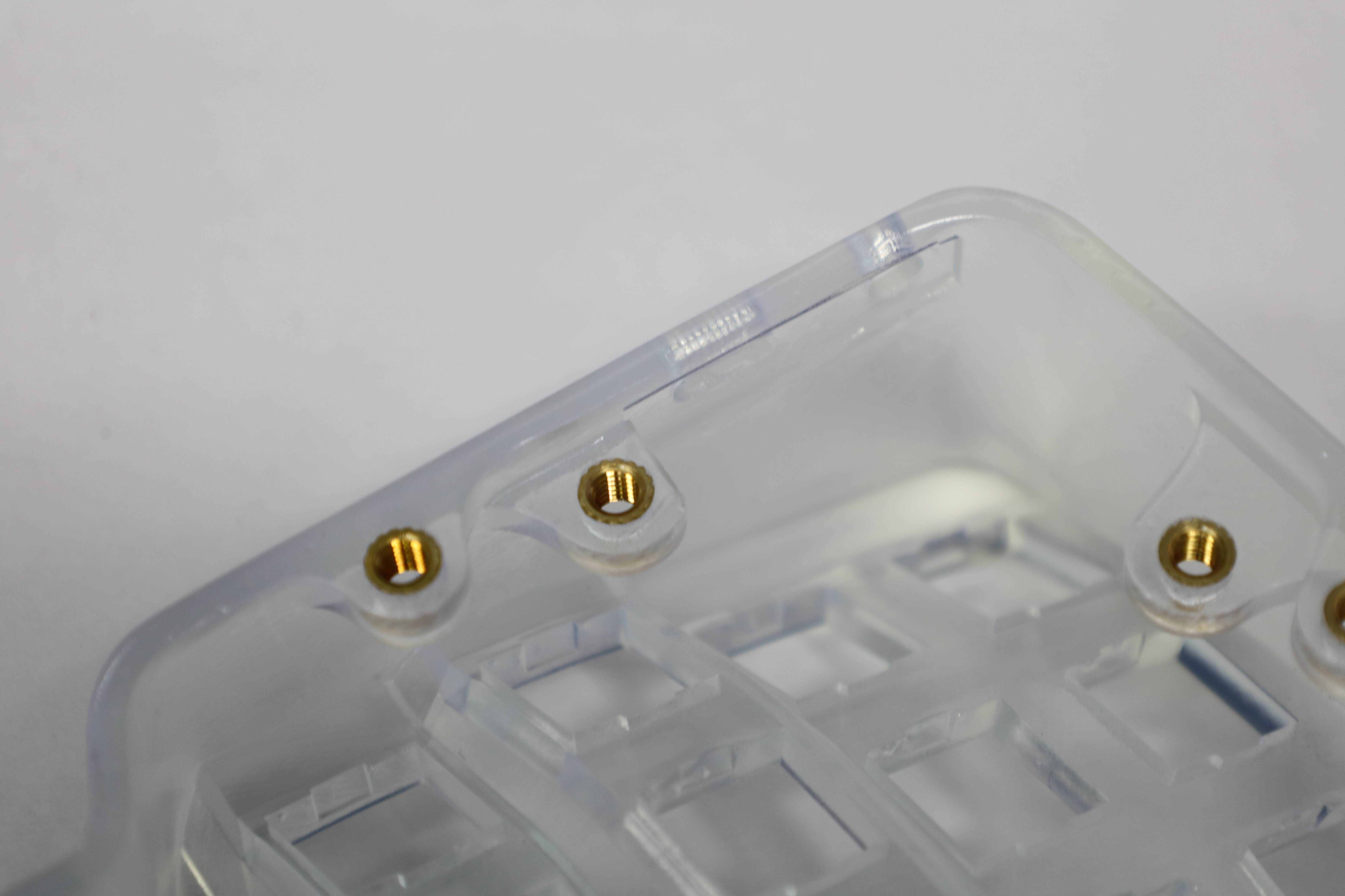
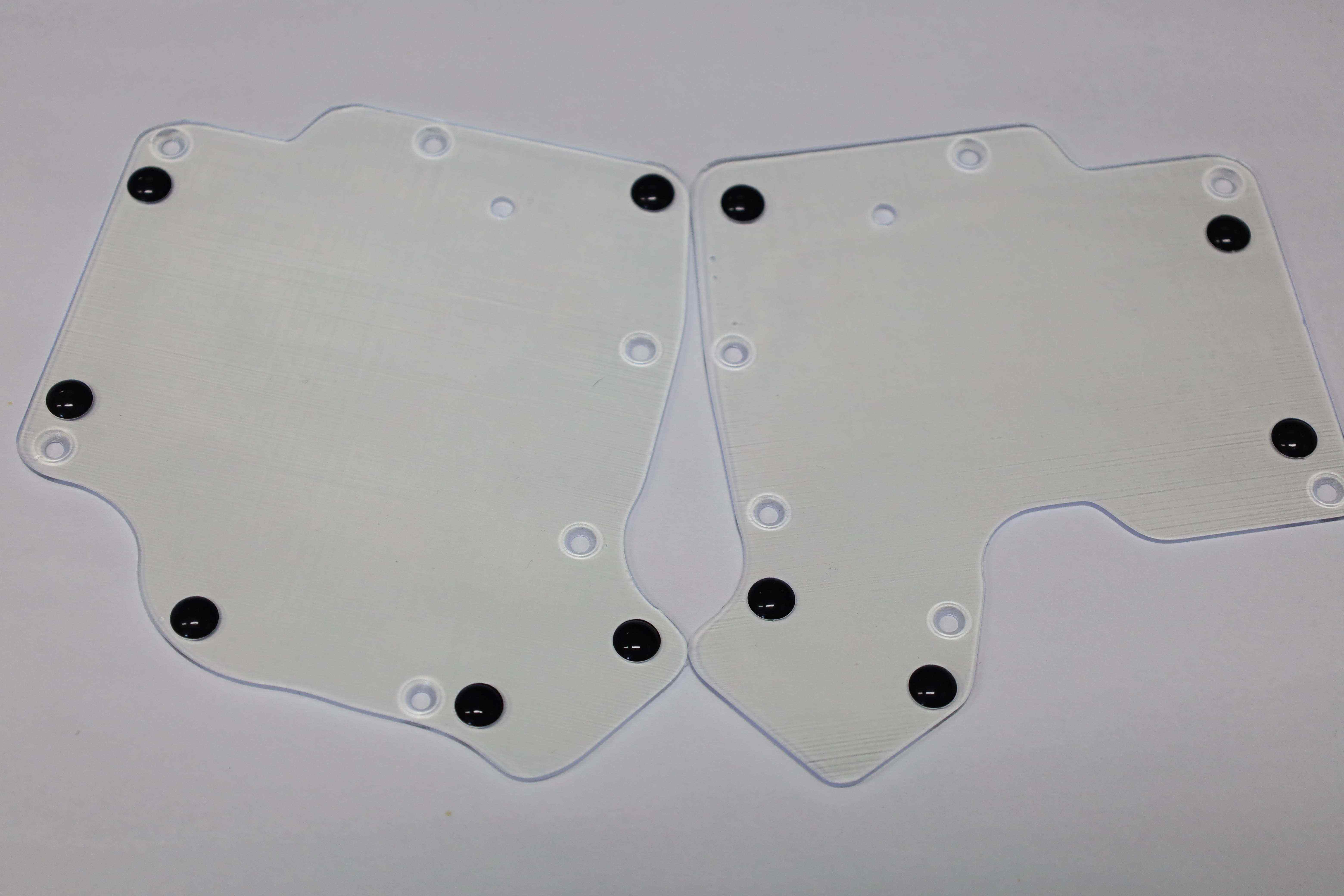
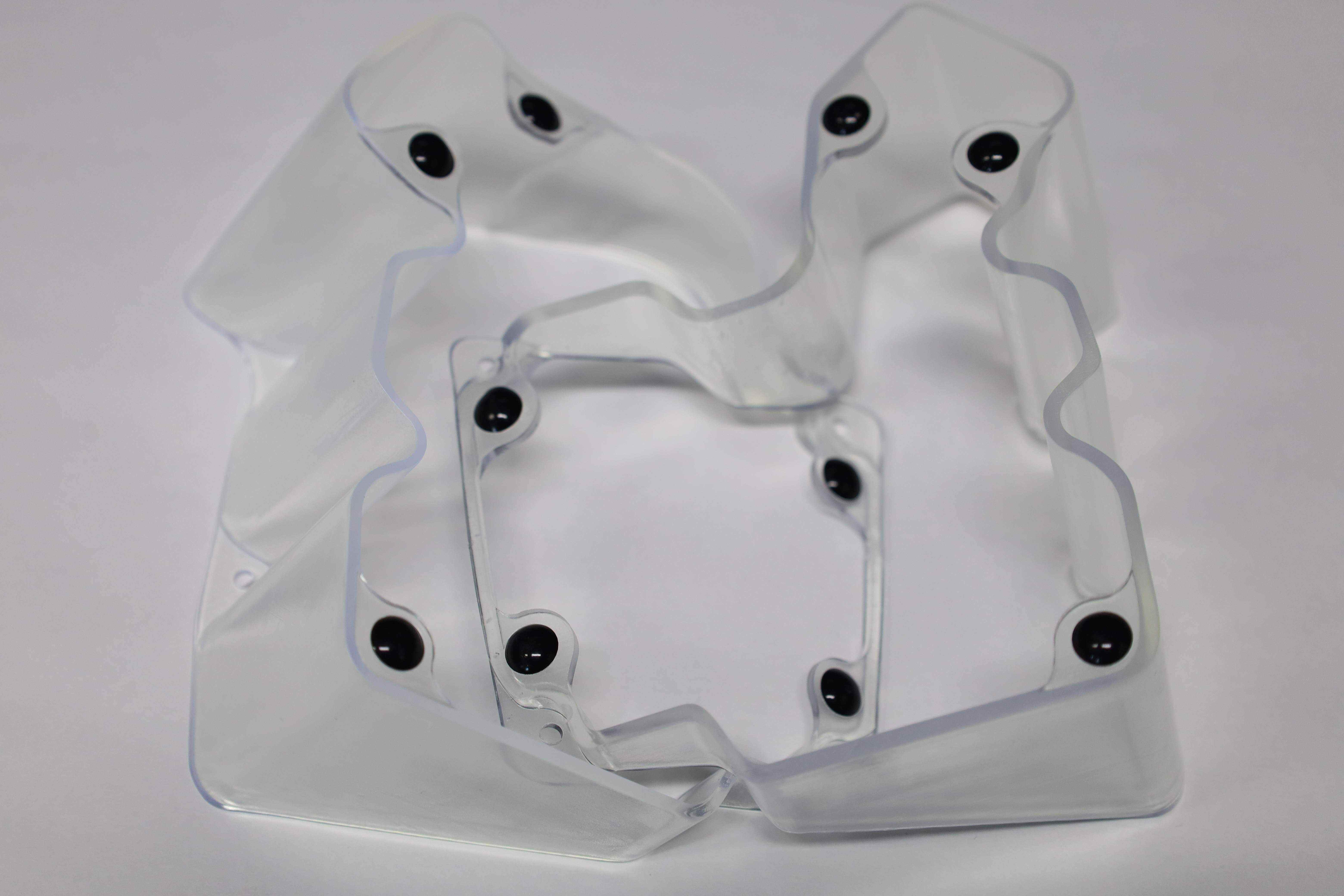
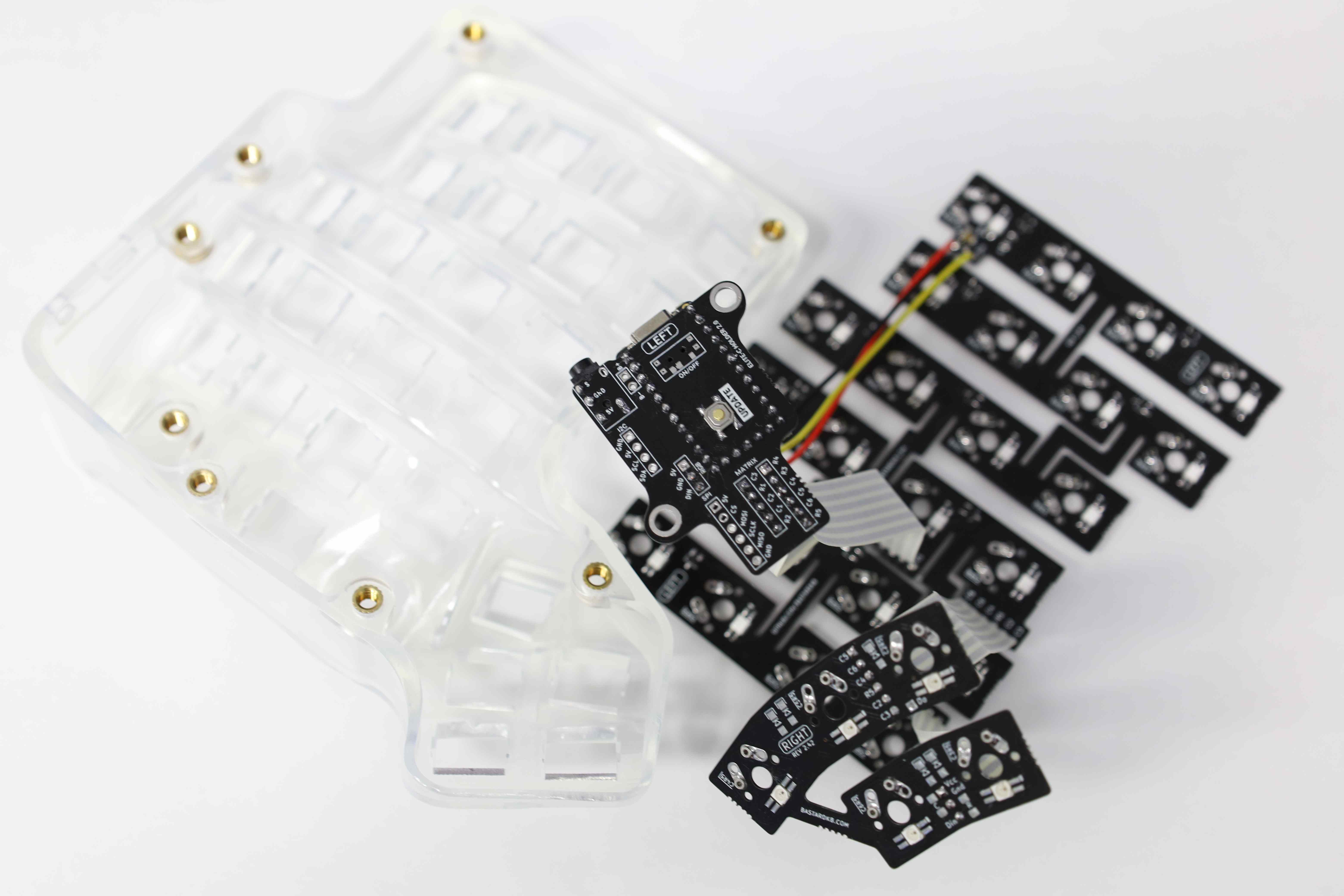
2. Preparing the case [Optional] [Left, Right]
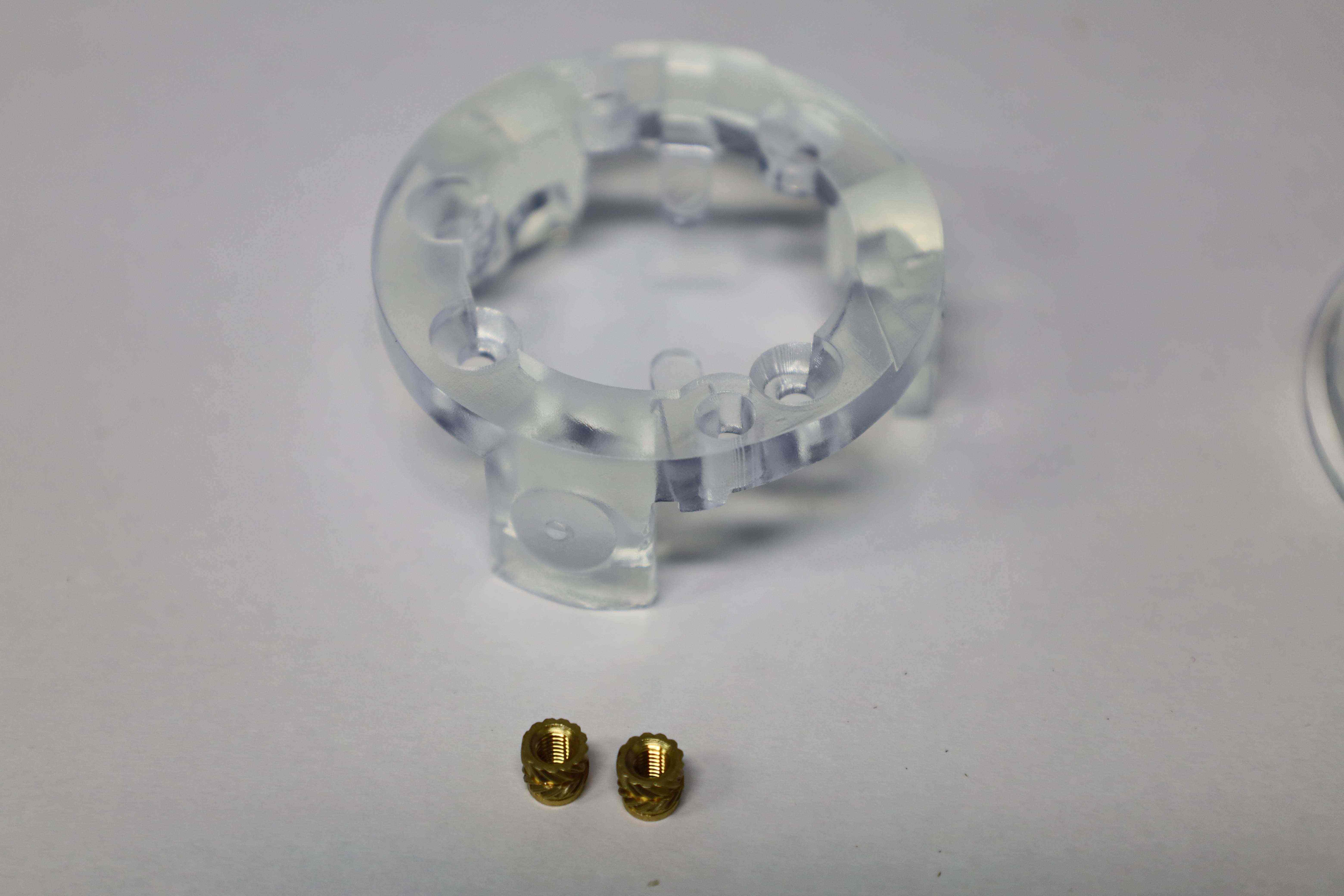
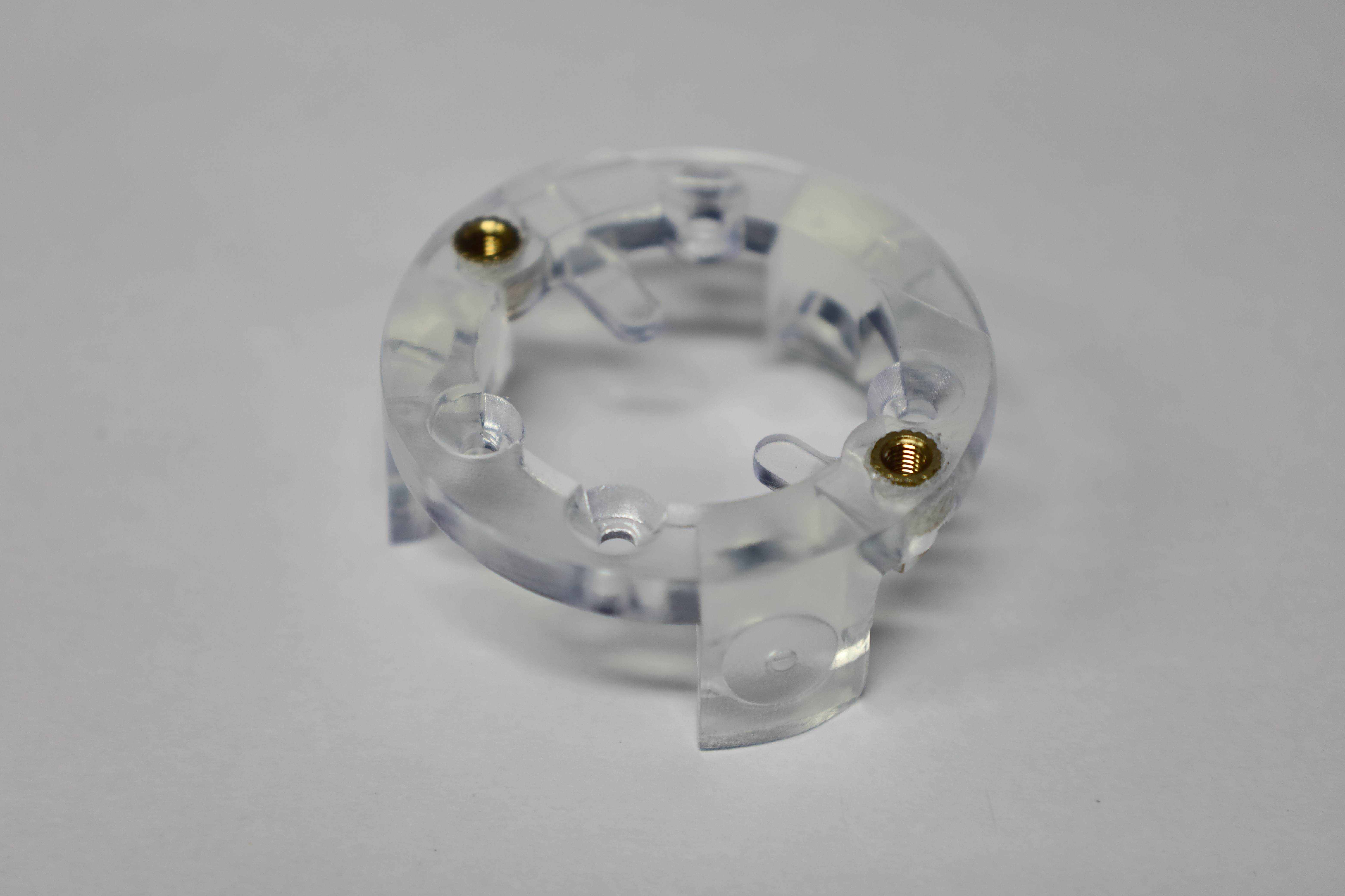
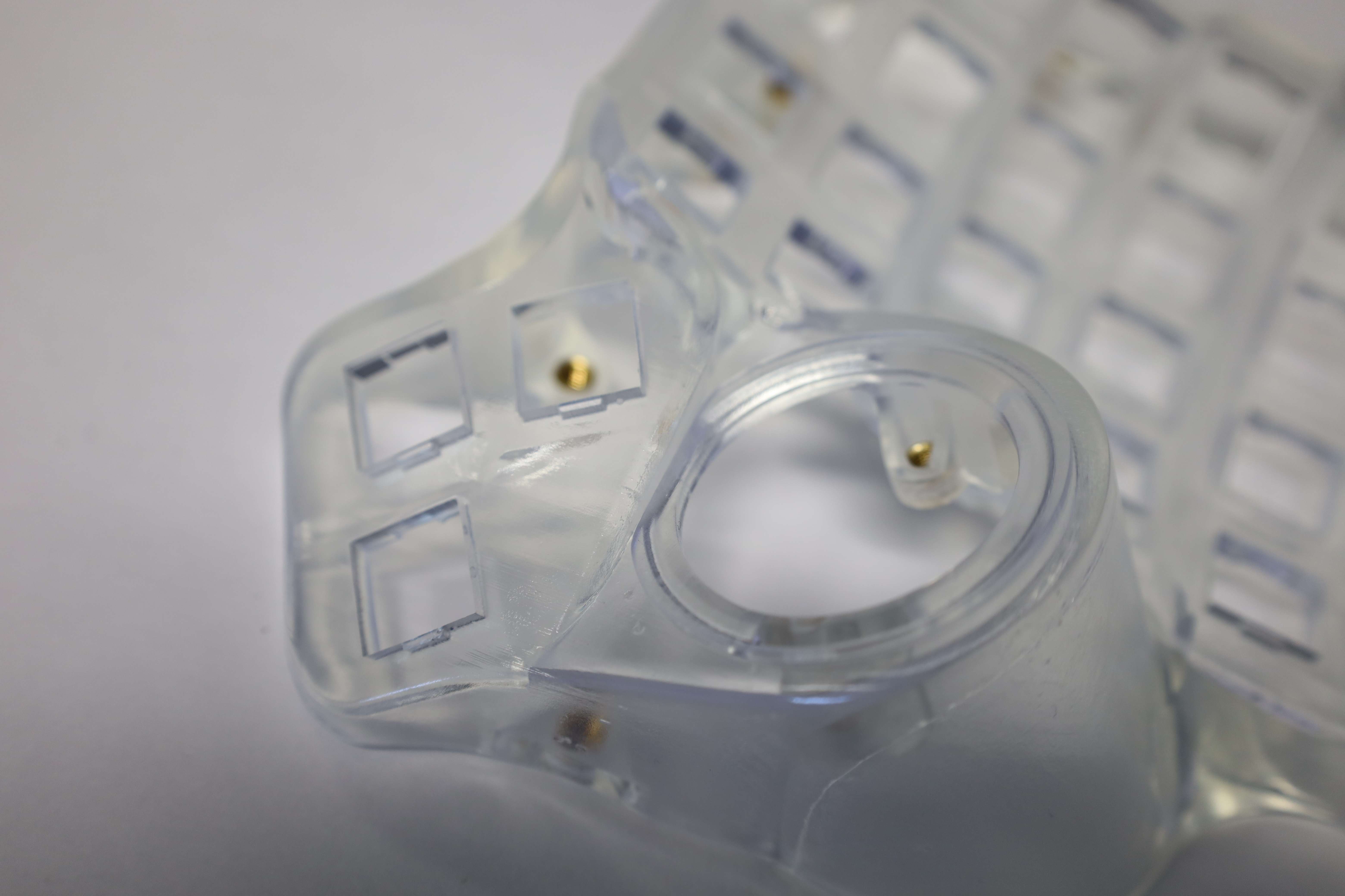
Once the printed case is all clean and ready for assembly, the next step is to add the inserts for the screws in the appropriate locations. For this specific clear case, the resin material seems to have a higher melting temperature than FDM-based prints. Therefore, it required setting the iron around $280$ to $300$ degrees Celsius instead.
To be safe, it would be better to still start from 200 as per the guide, then increment the temperature slightly until the inserts can be melt-inserted into the case. The parts where the MCU shield has to be screwed later are especially fragile and should be handled with the lowest possible temperature and gentleness during the insert.
[Left side]

[Right side]
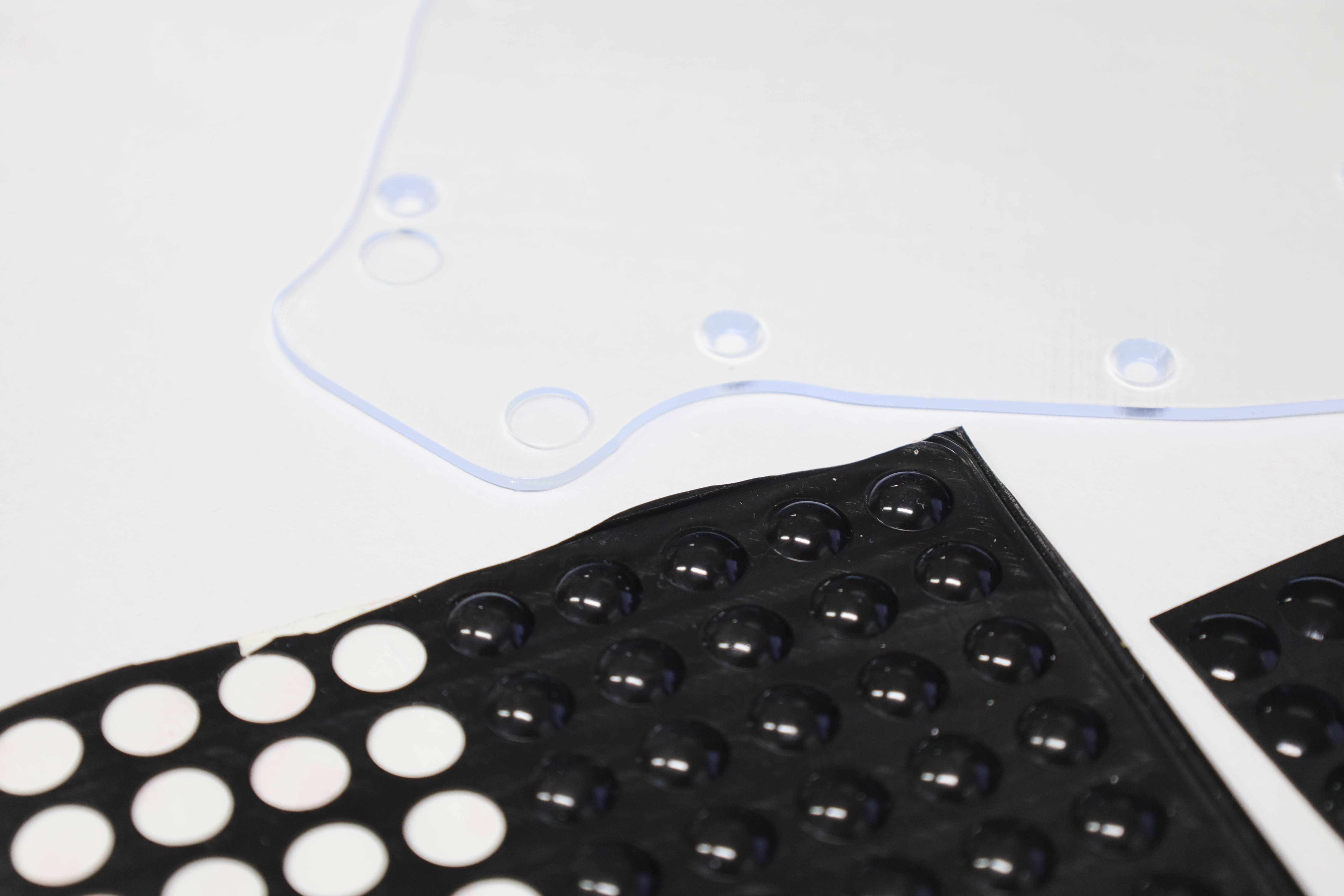
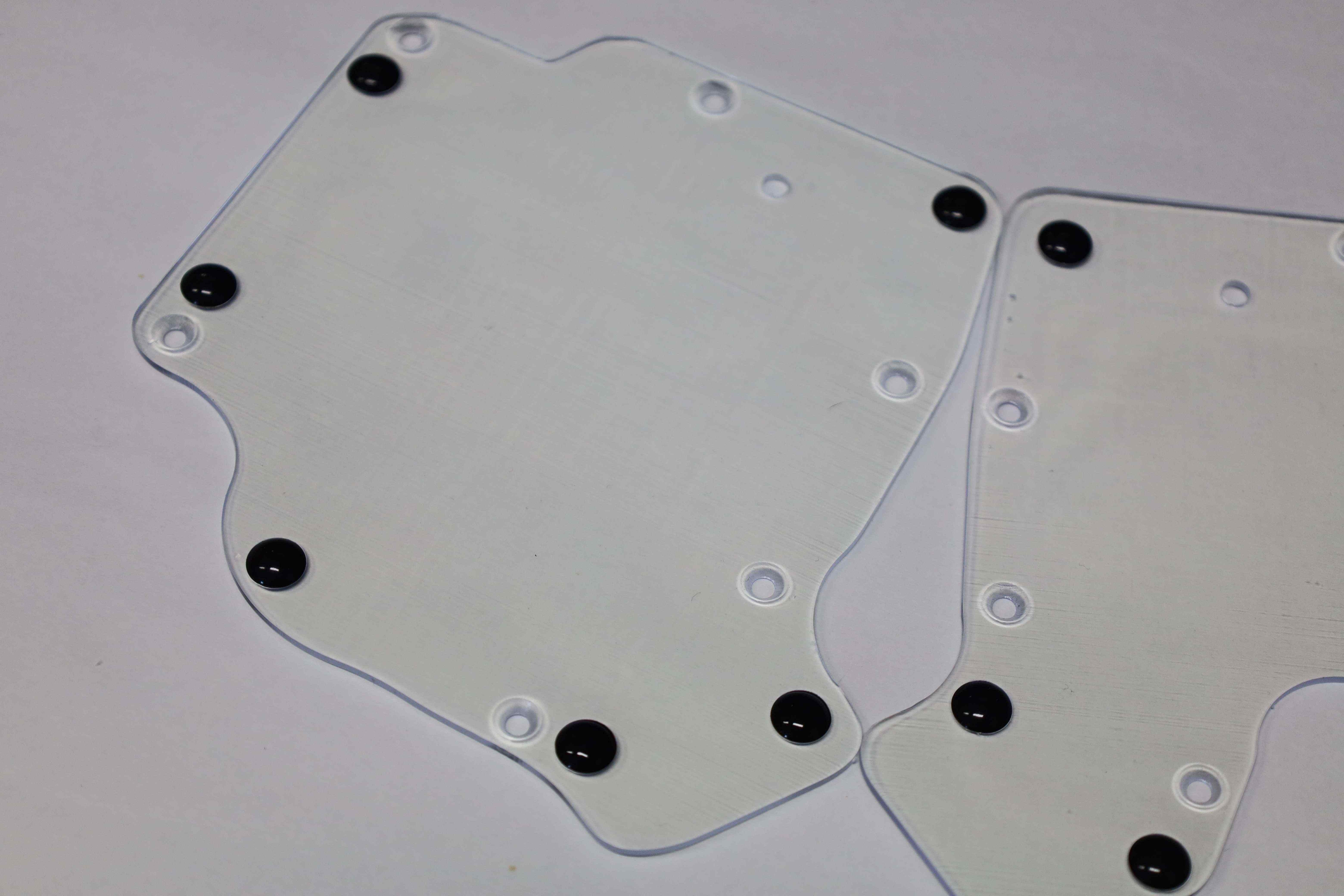
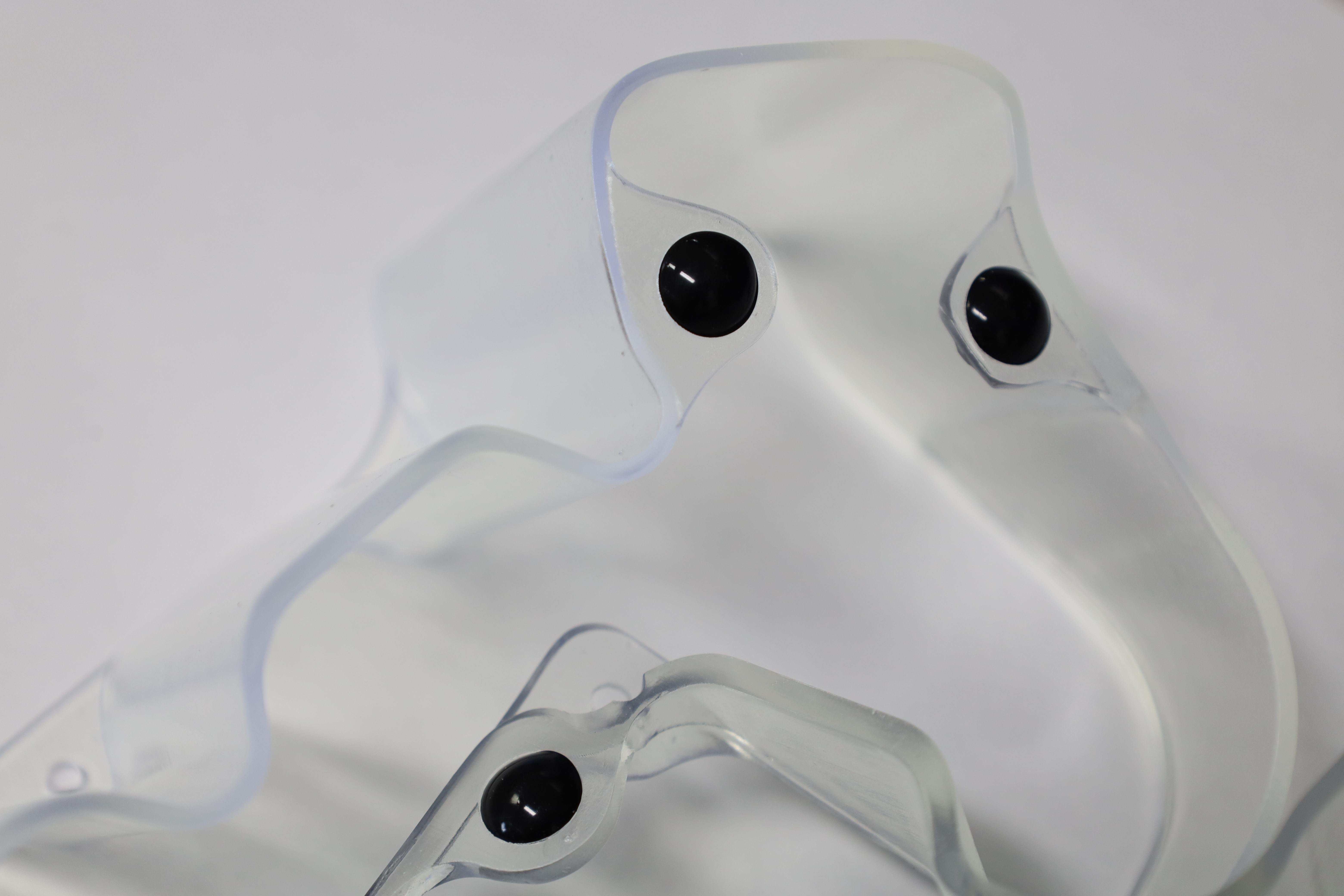
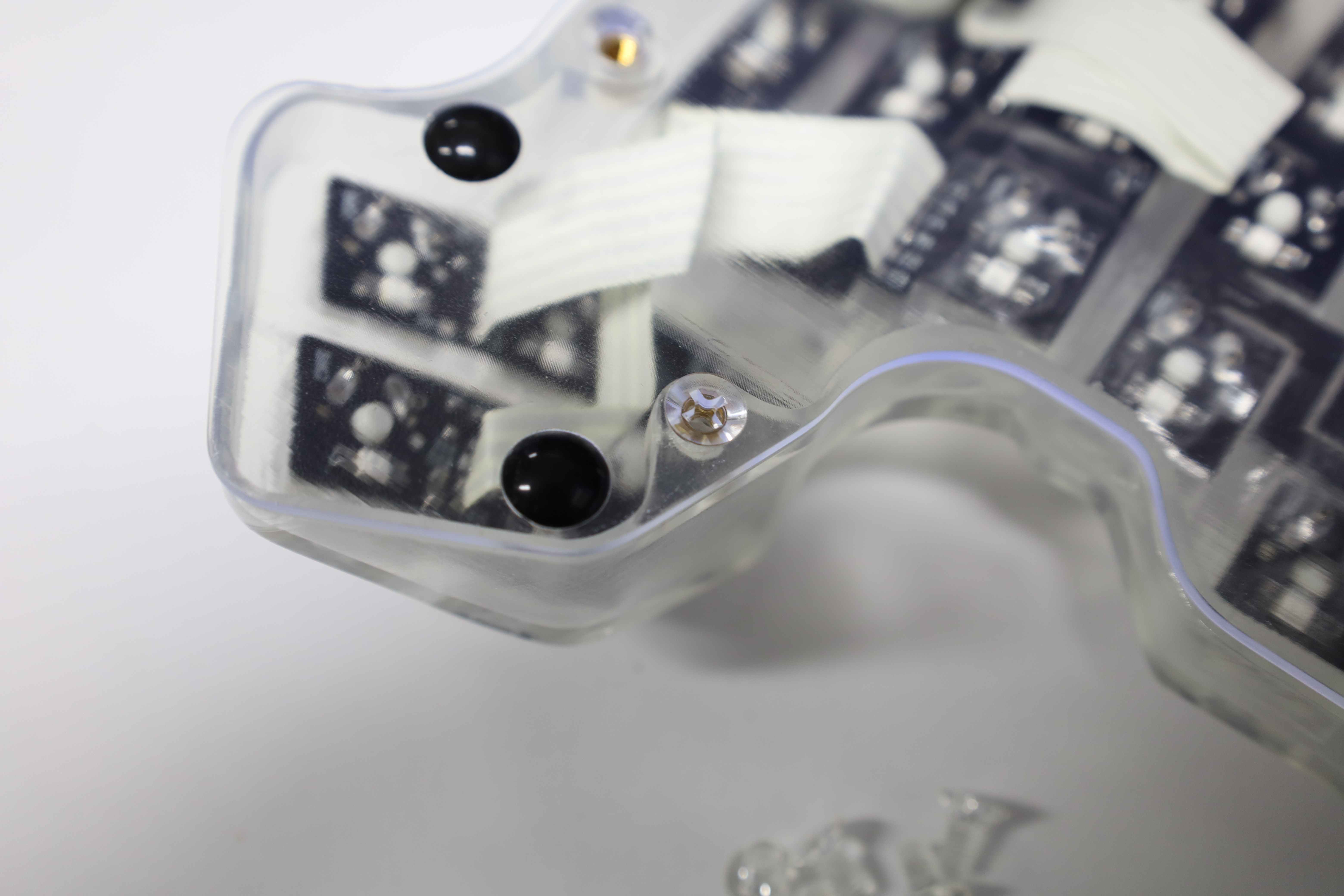
We take this opportunity to also install the anti-slip pads on the bottom plates, as well as the bottom-facing sides of the tents. While we use black-colored ones here, transparent ones should be harmonized even better with the clear case.
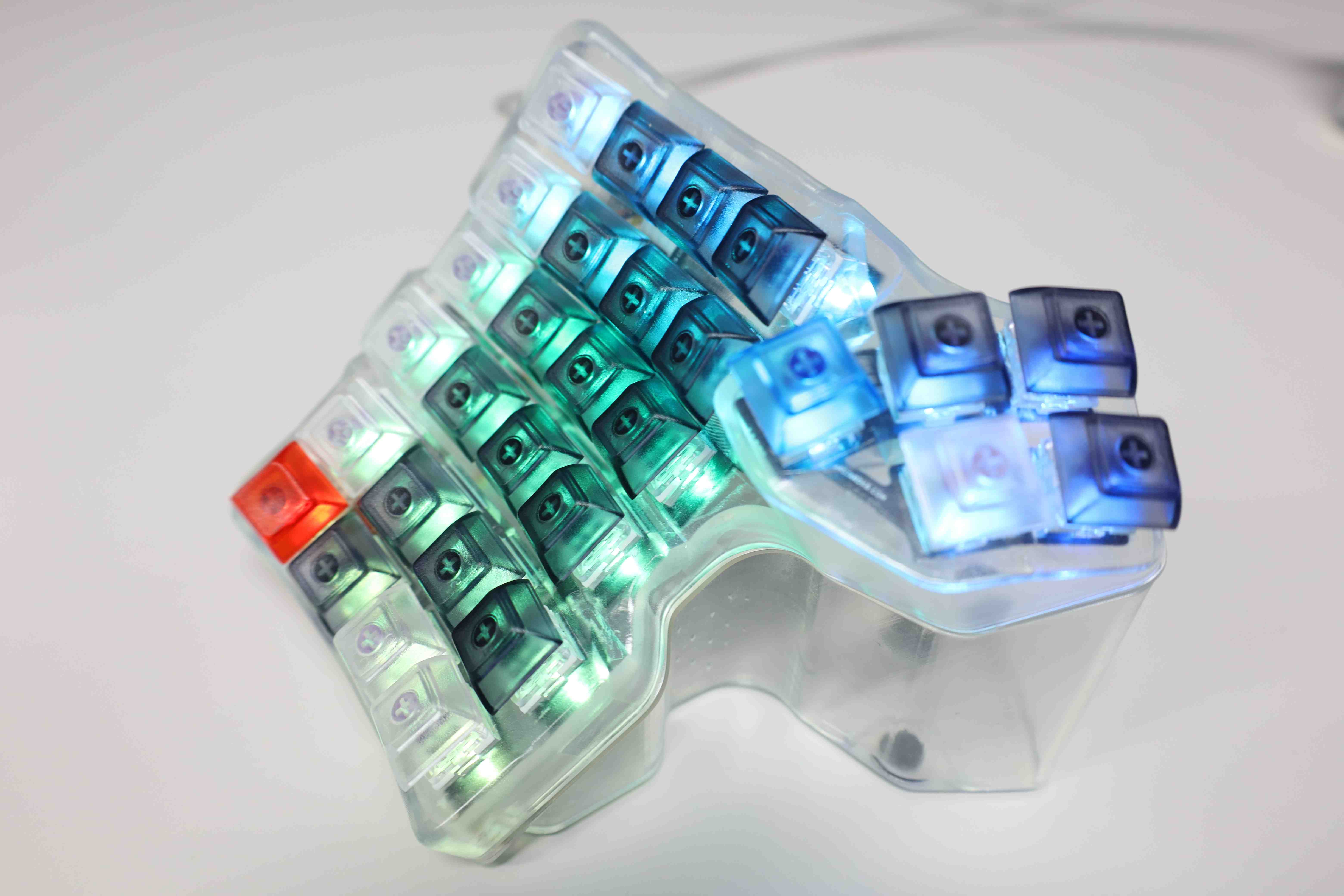
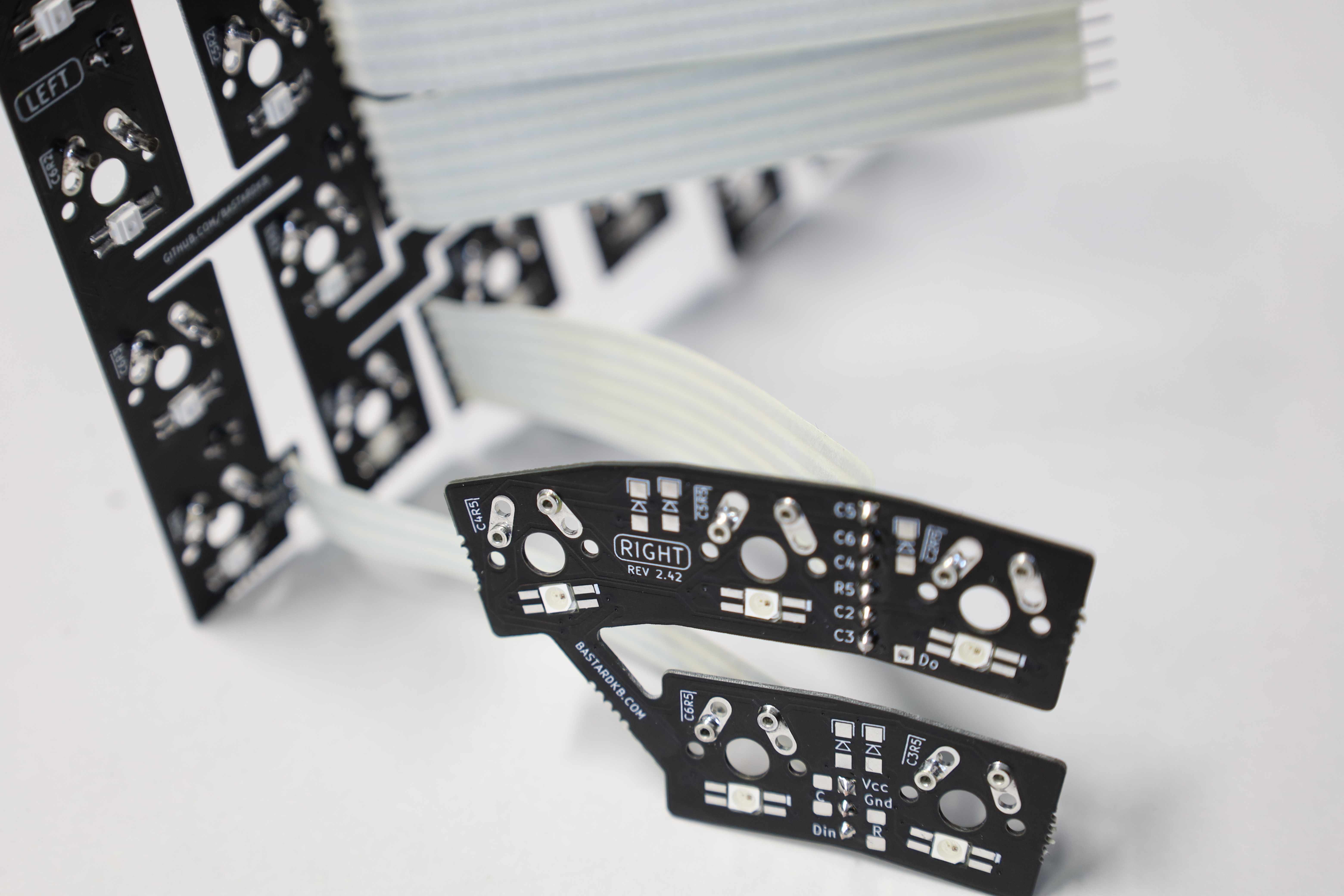
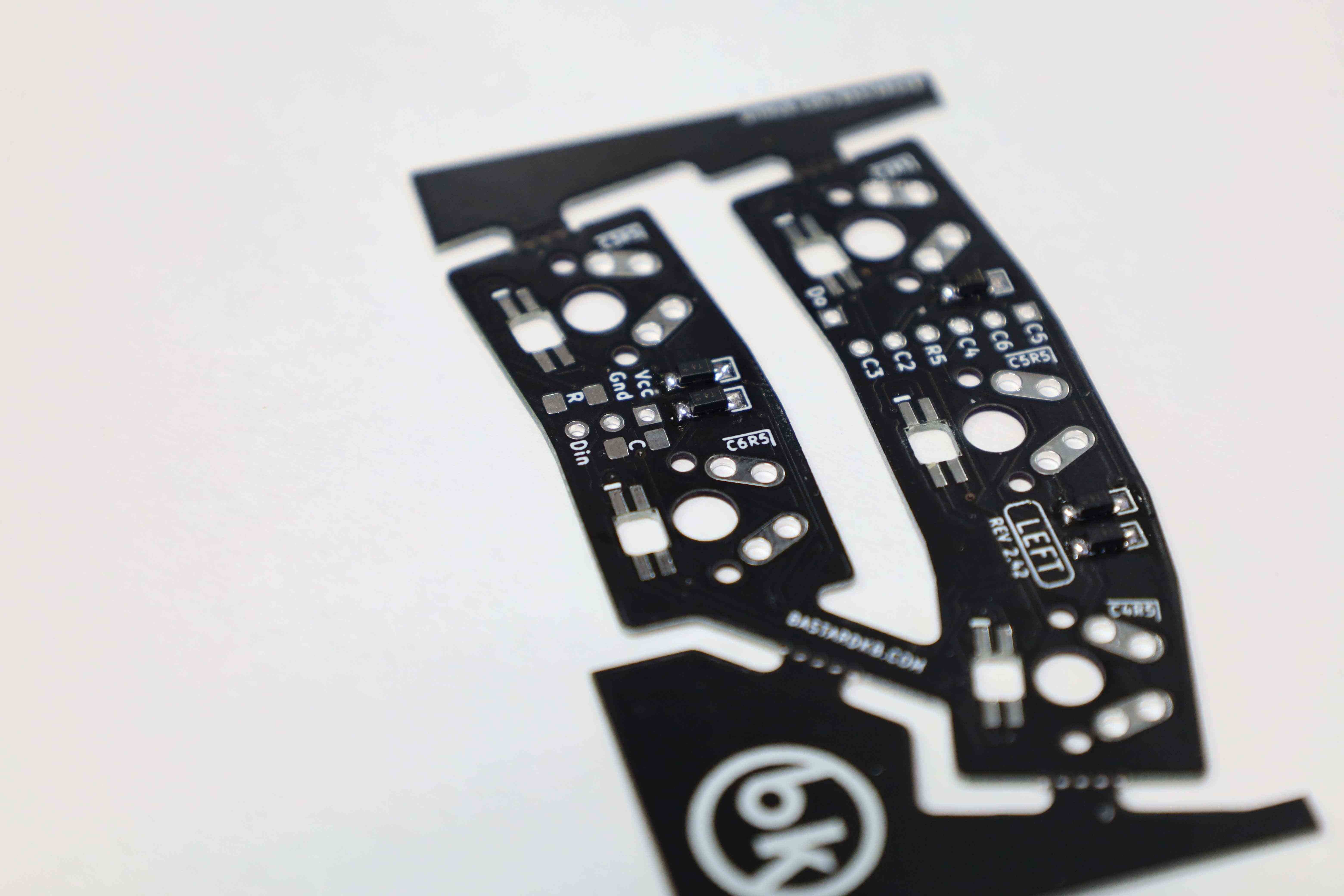
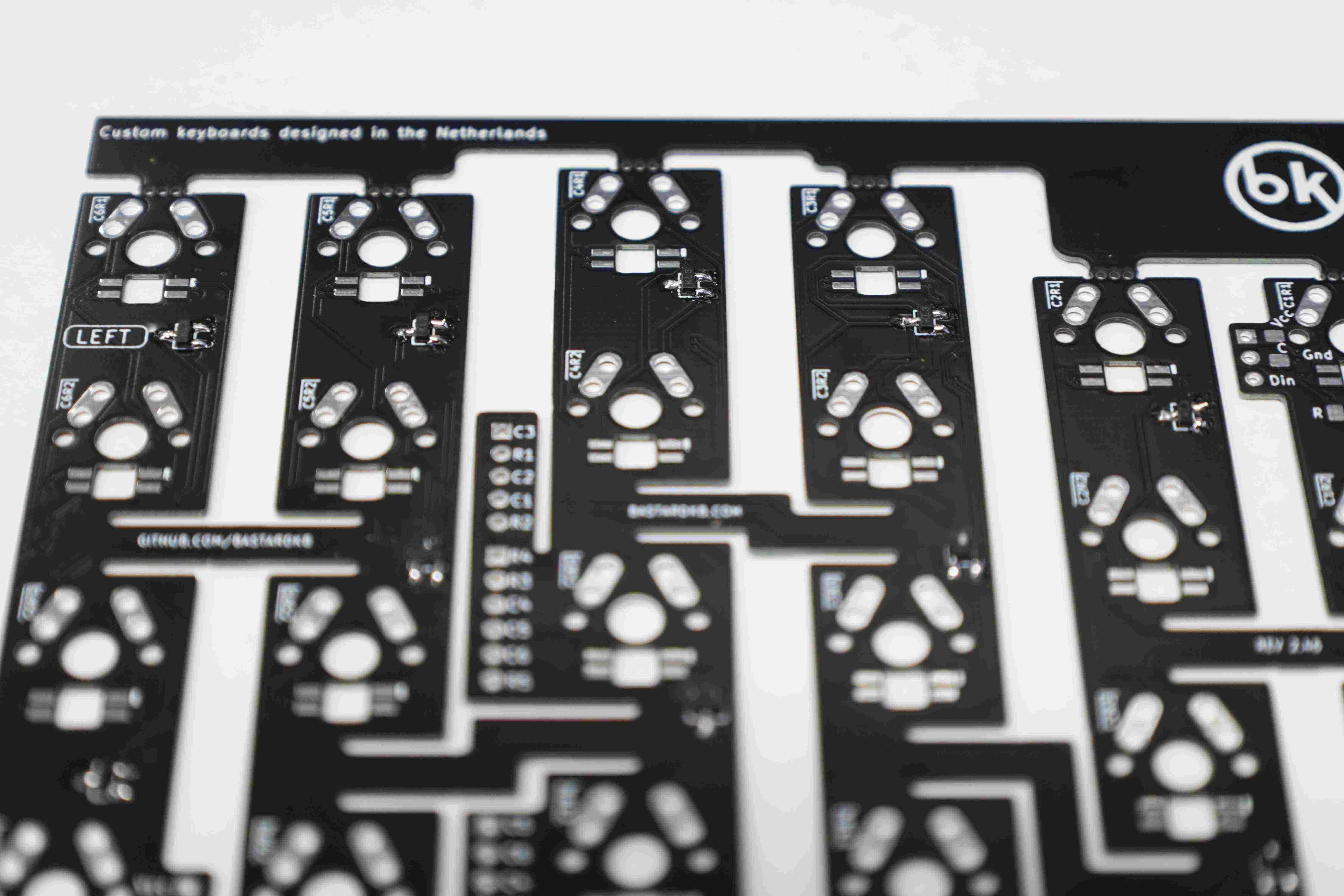
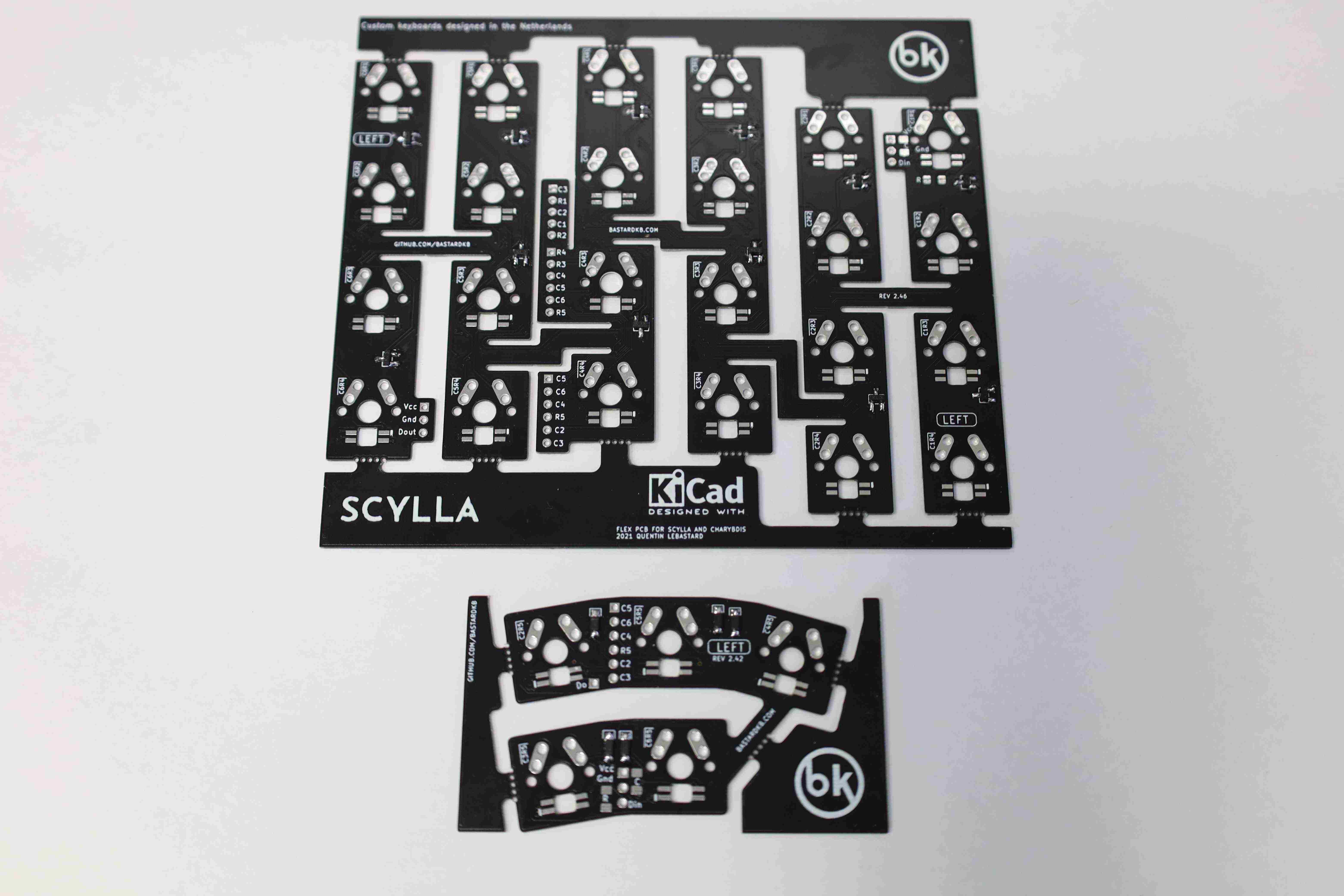
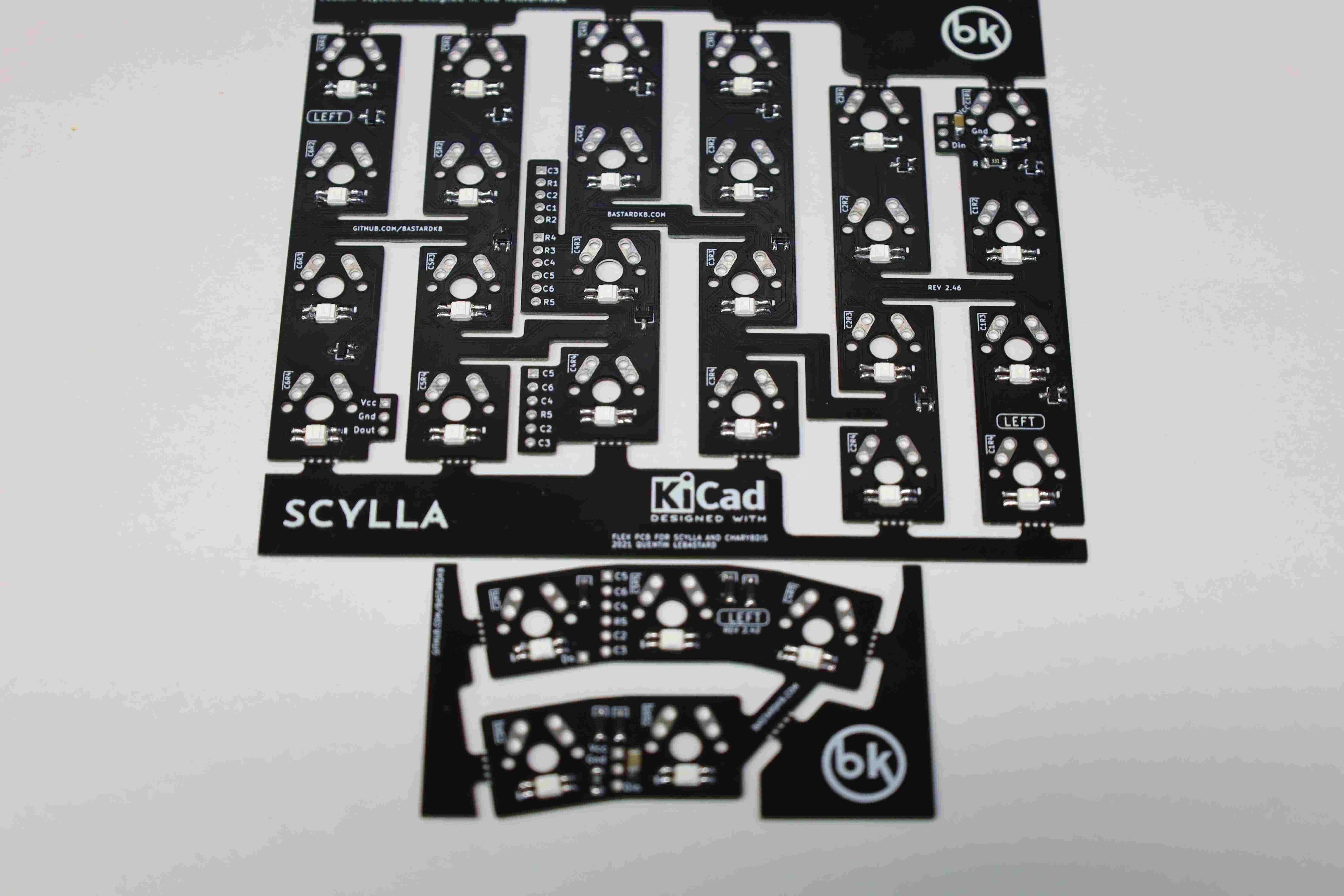
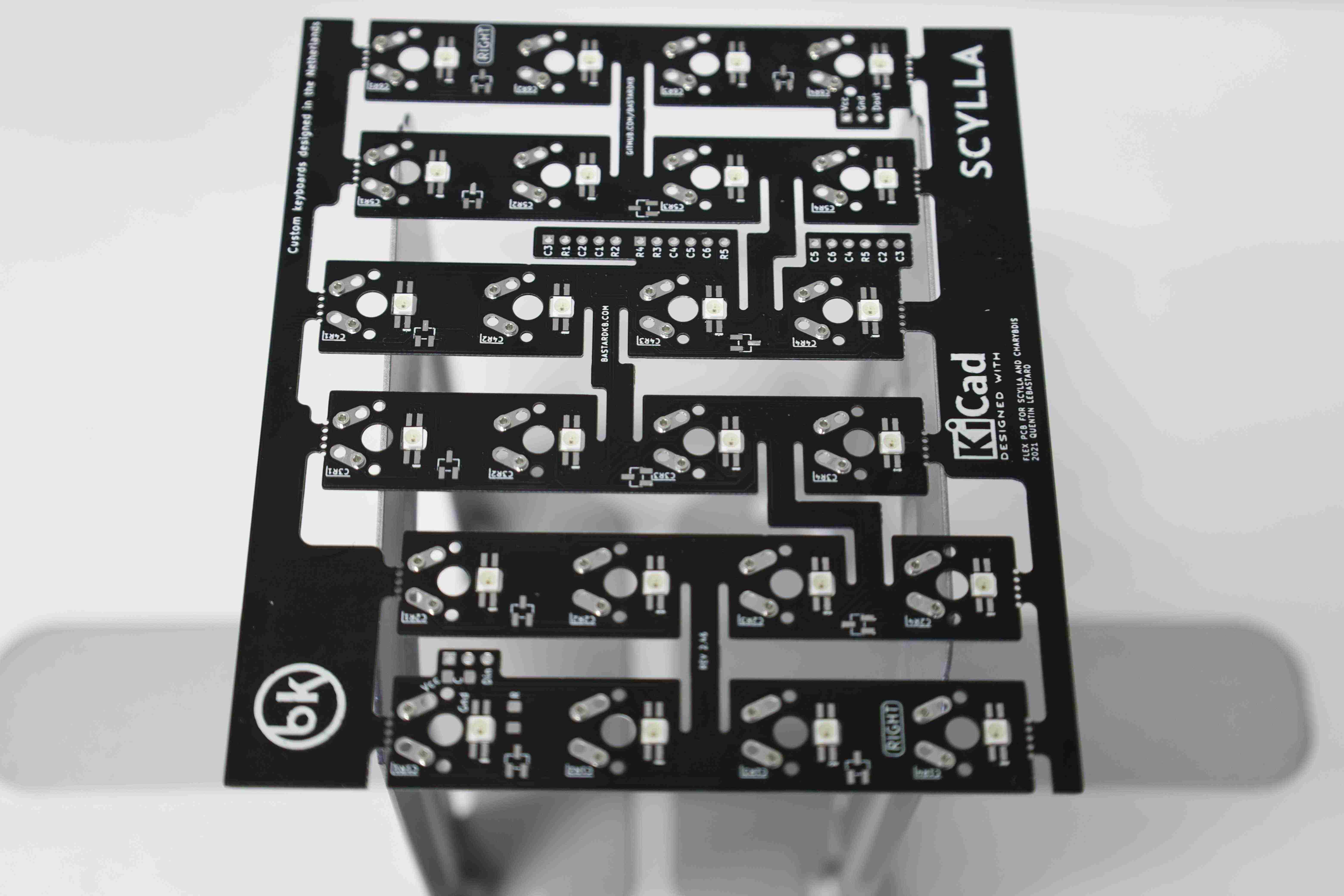
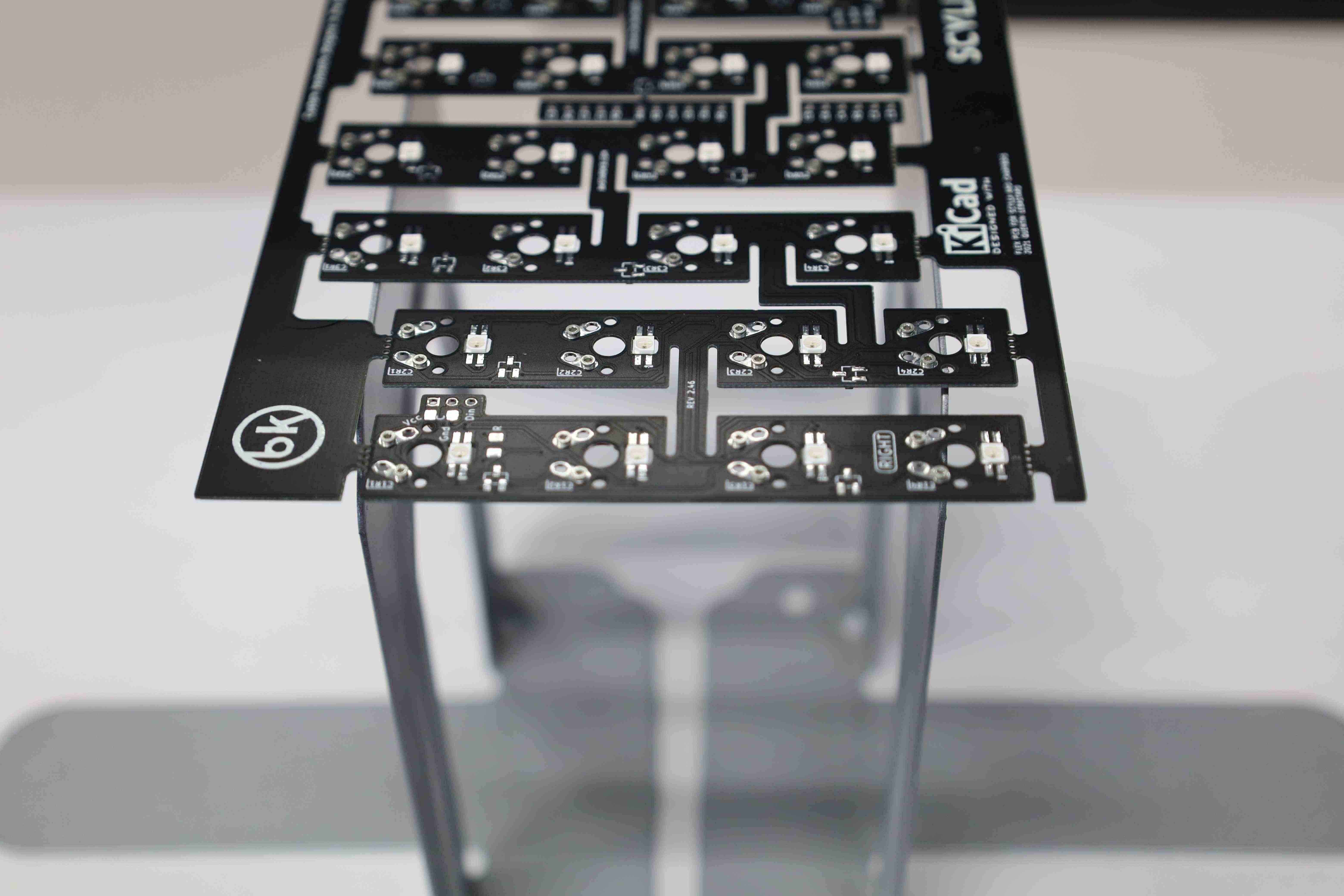
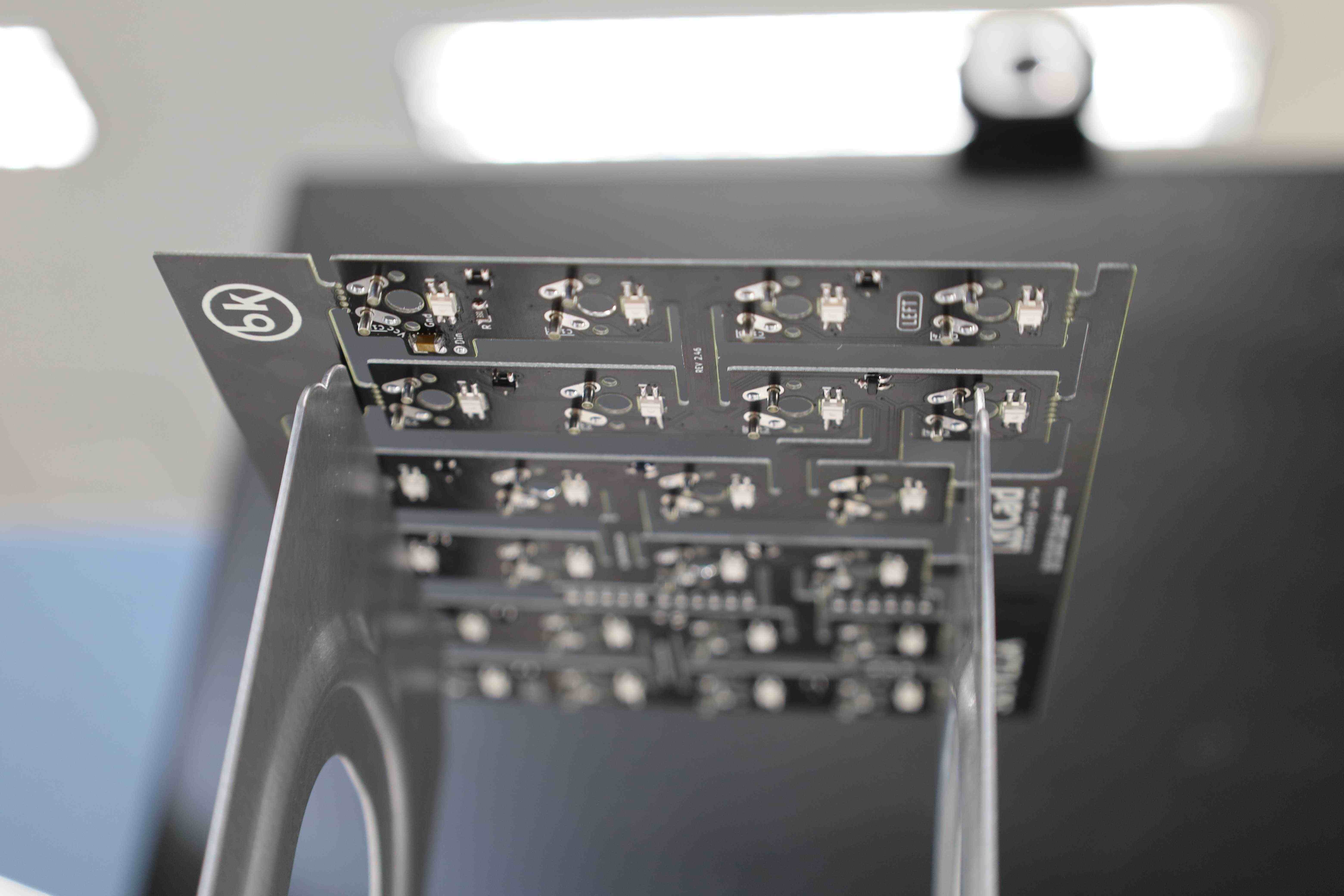
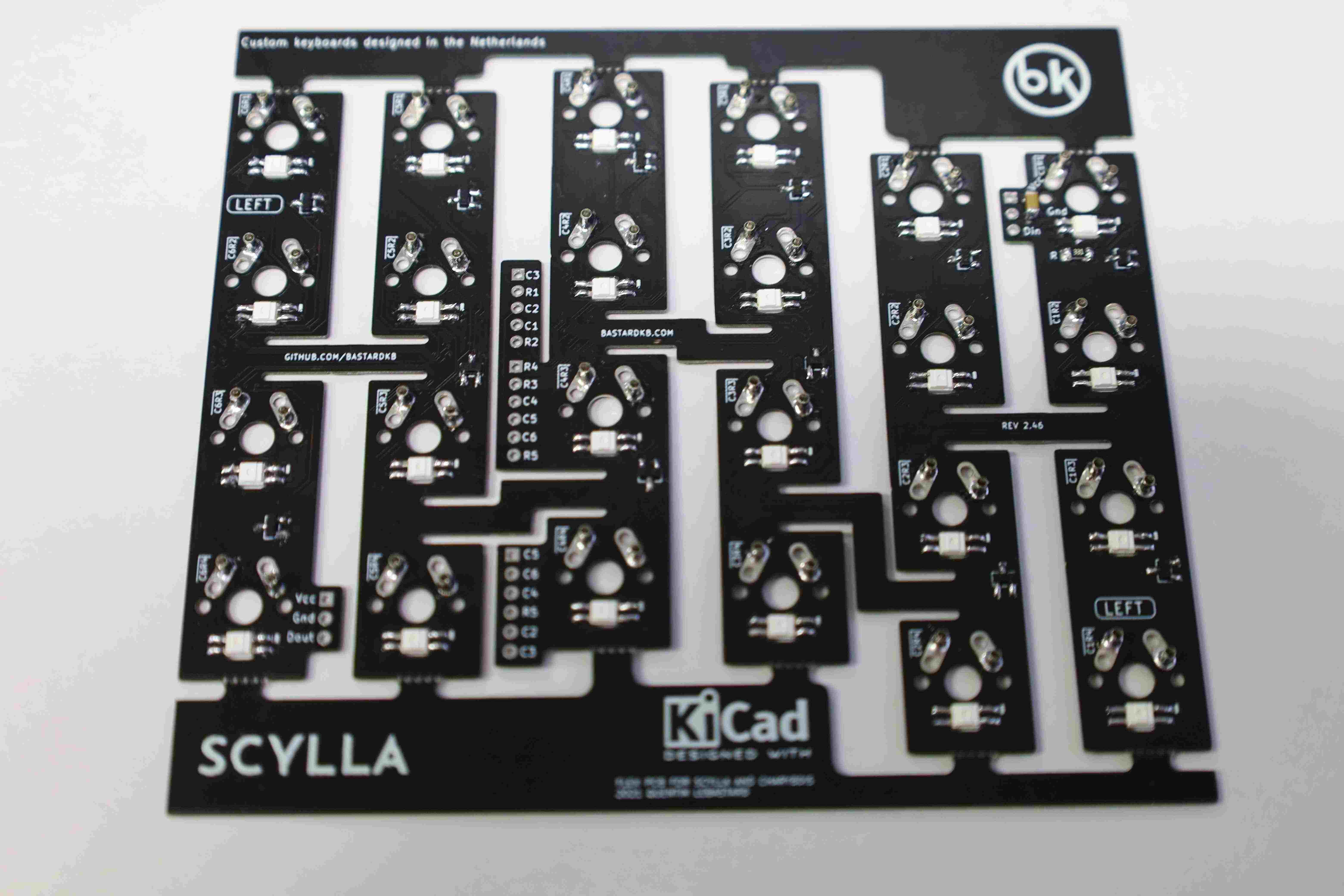
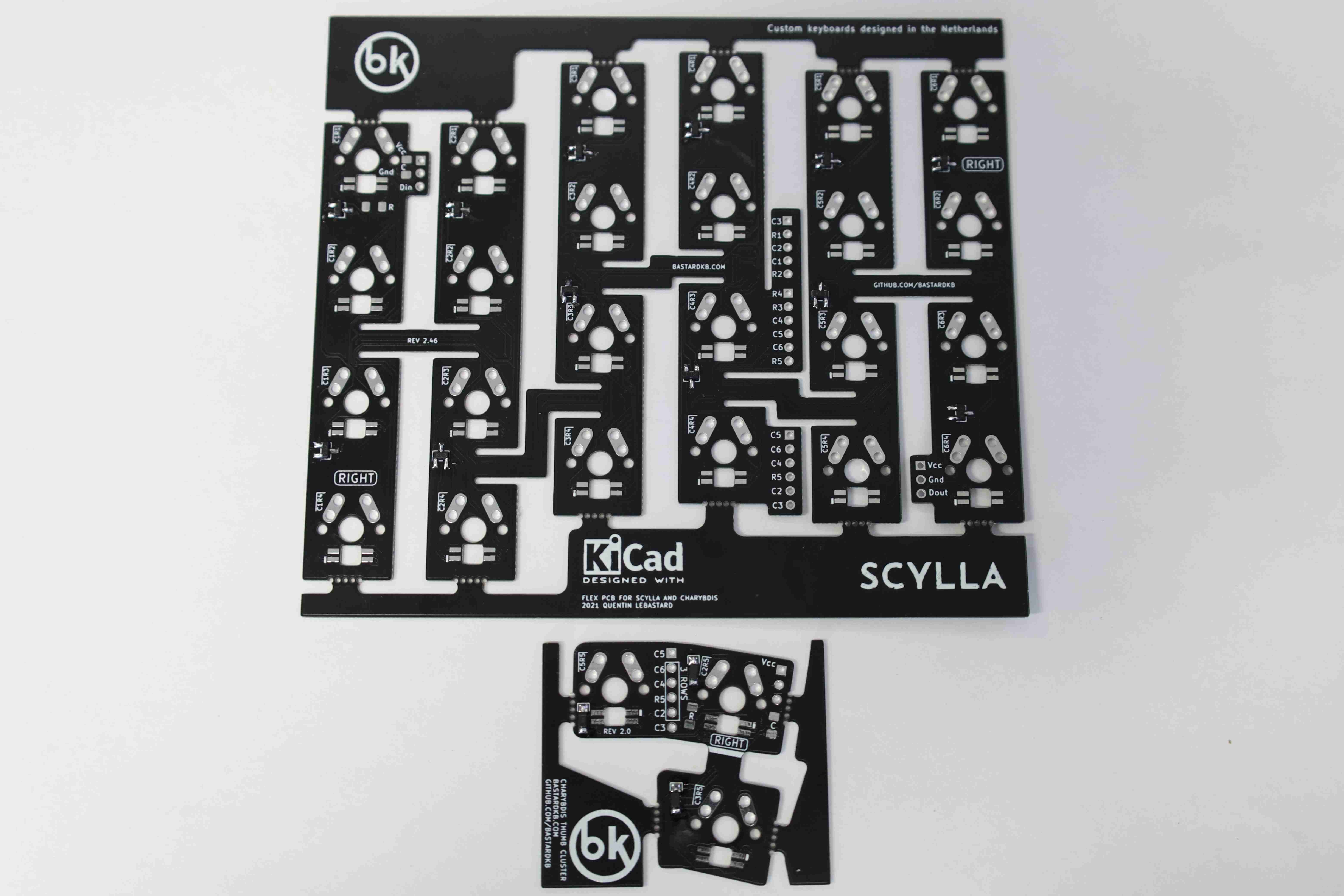
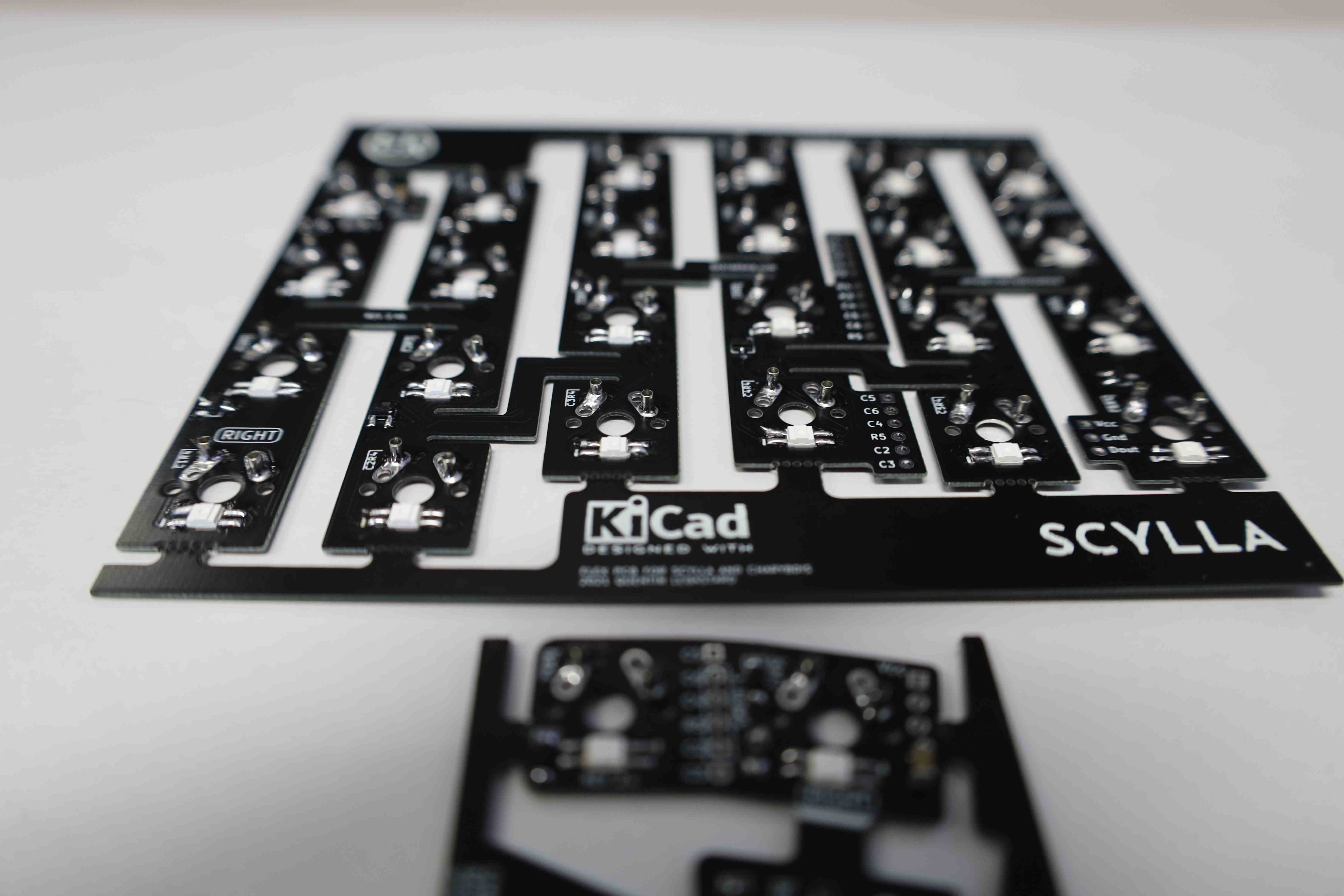
3. Left side: Scylla
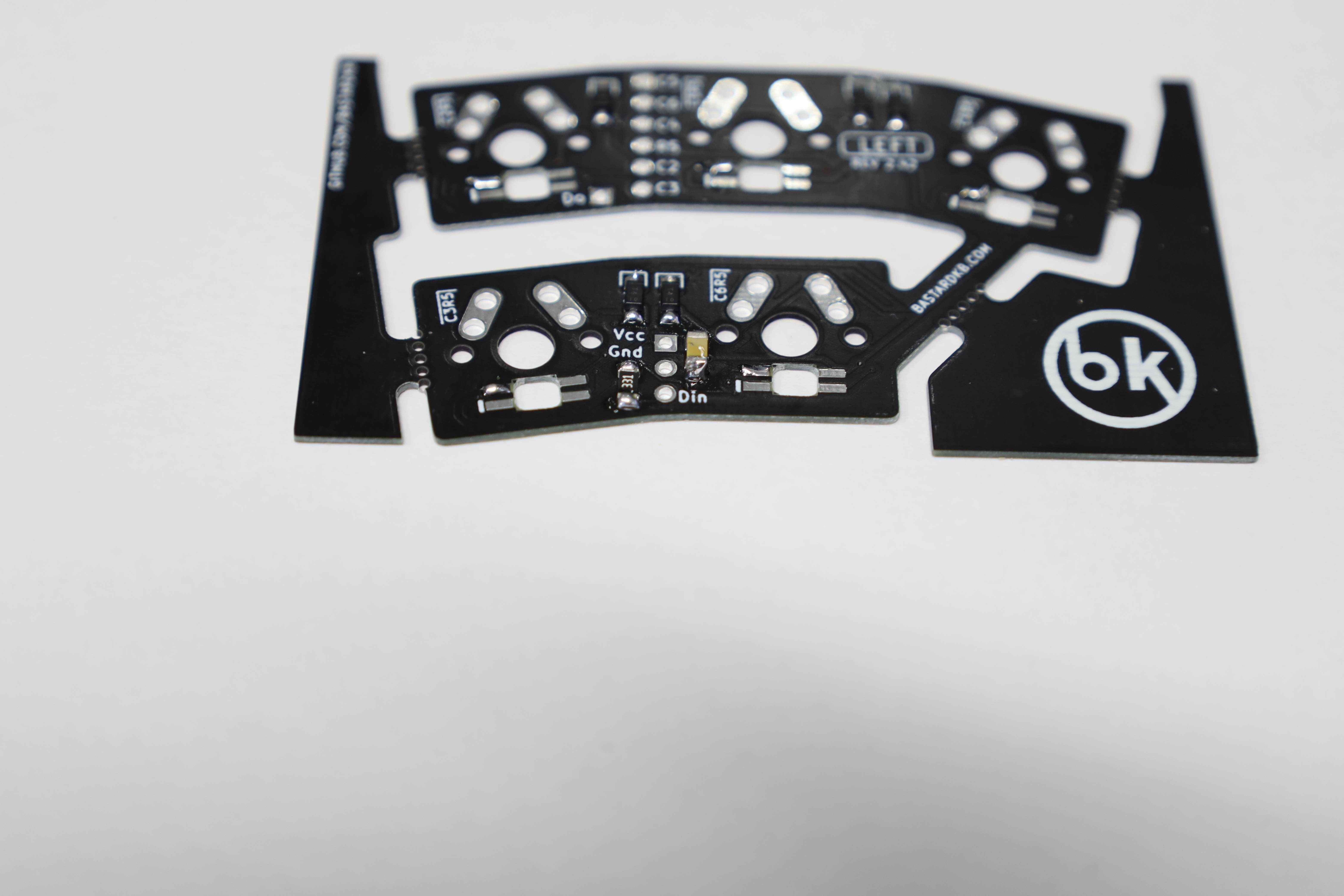
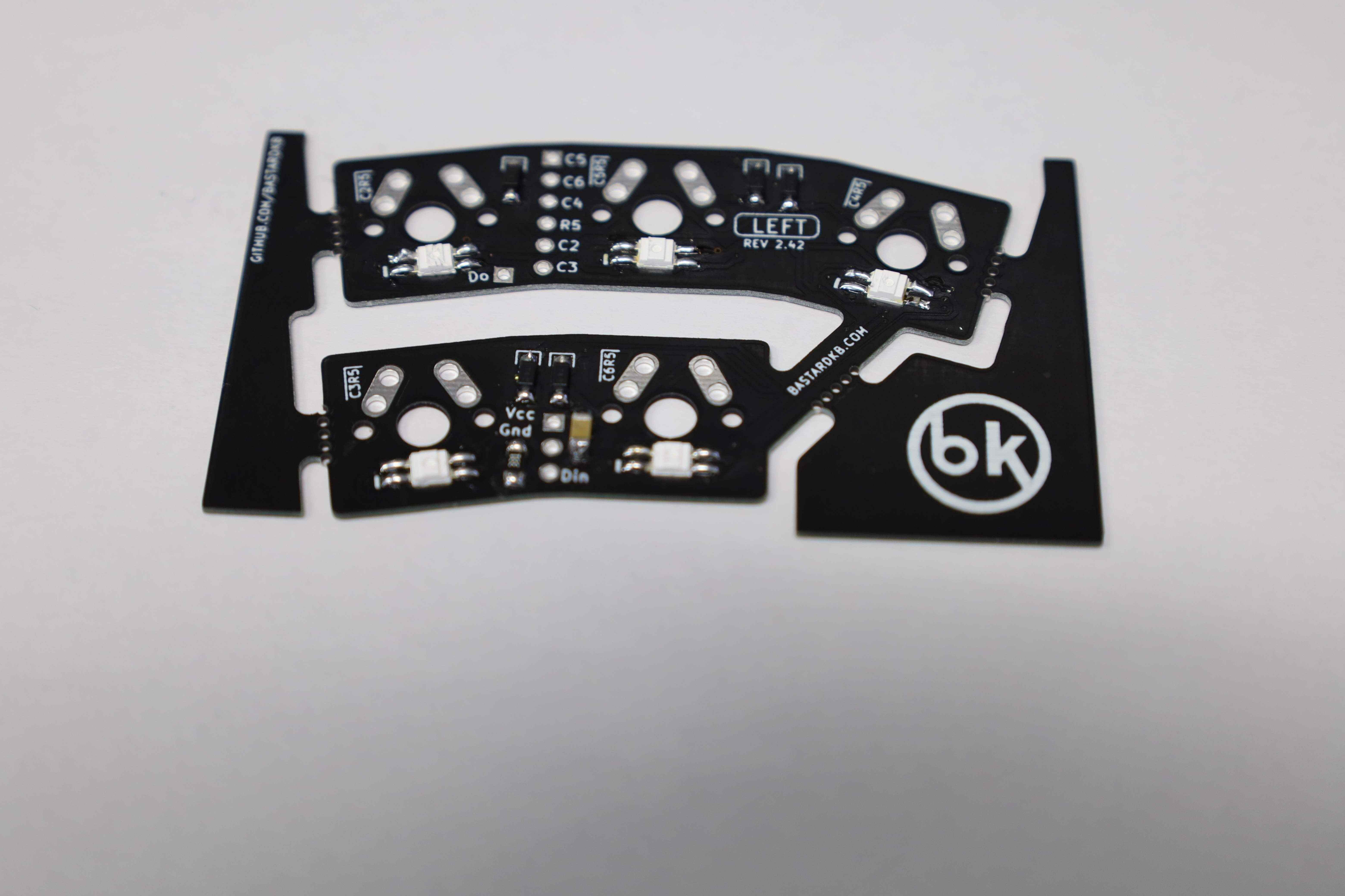
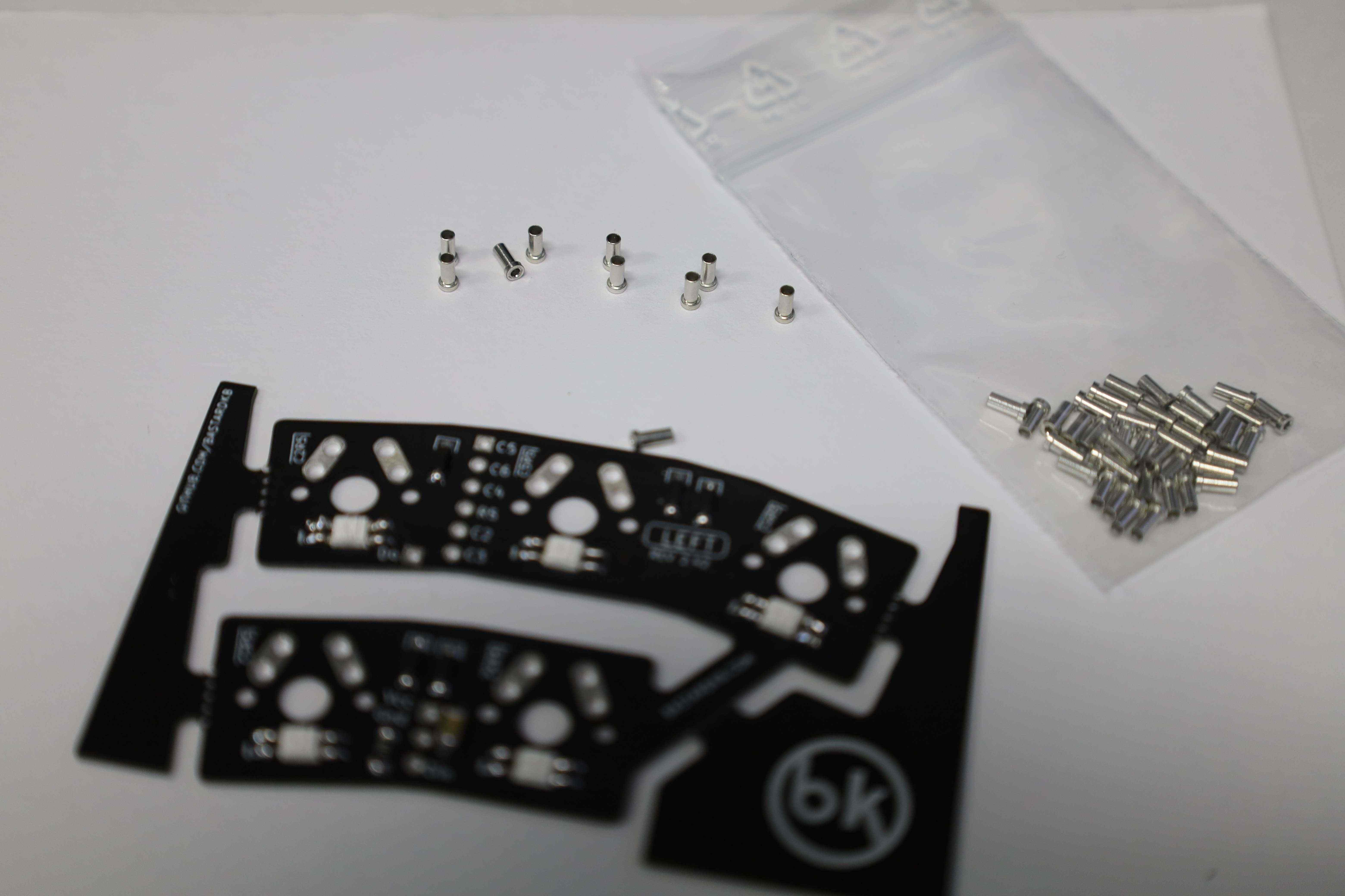
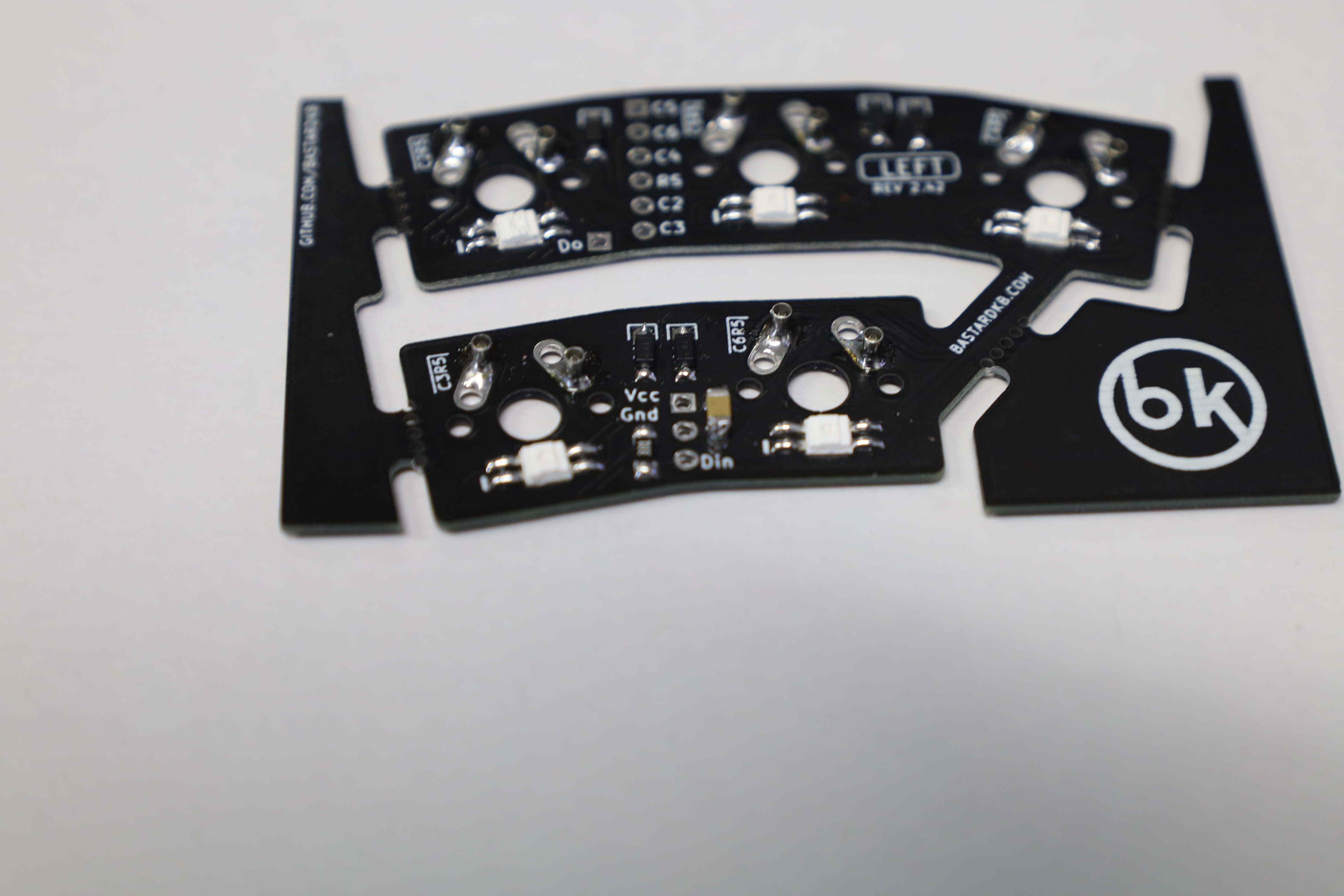
3.1 Installing the diodes
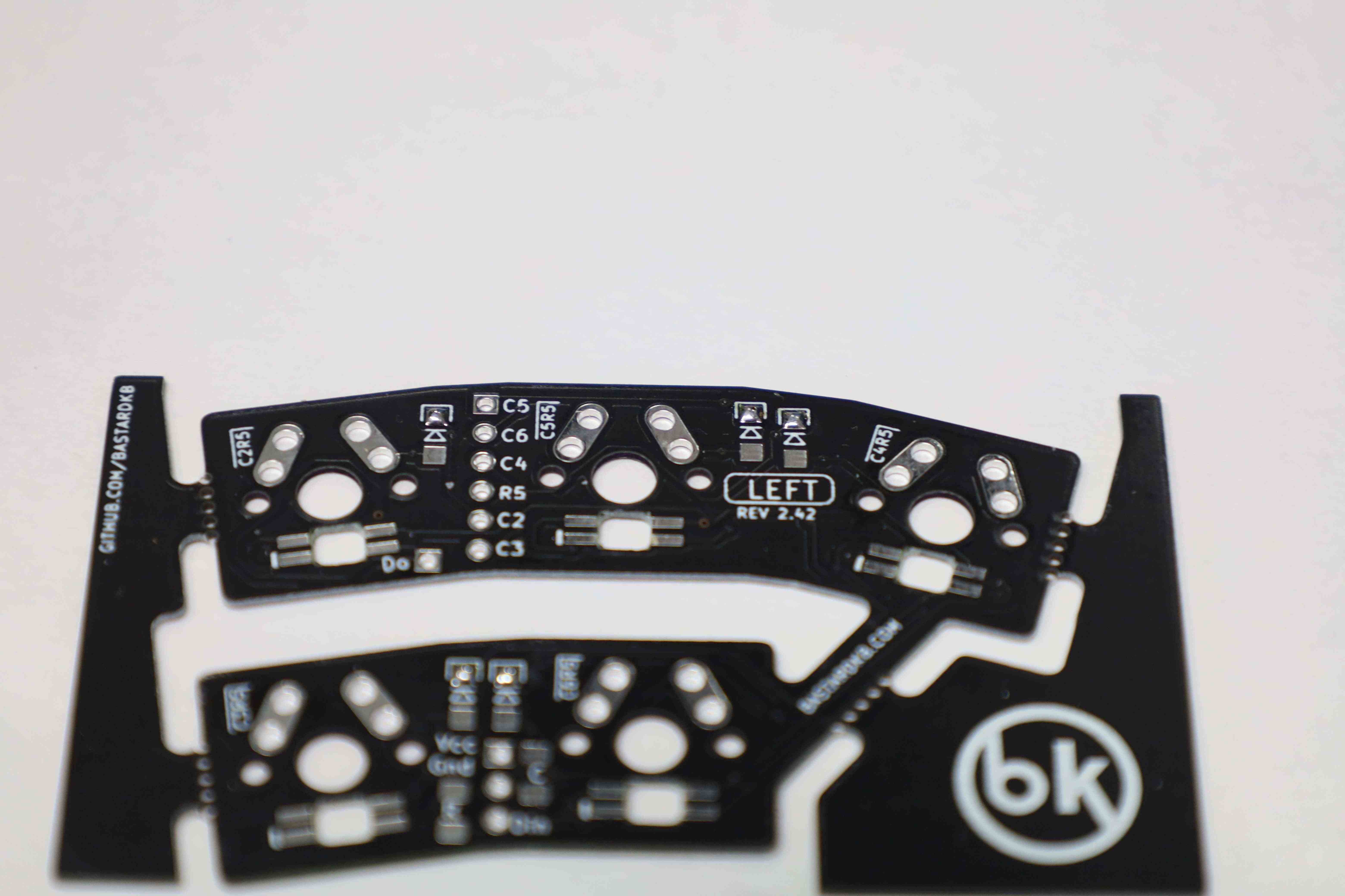
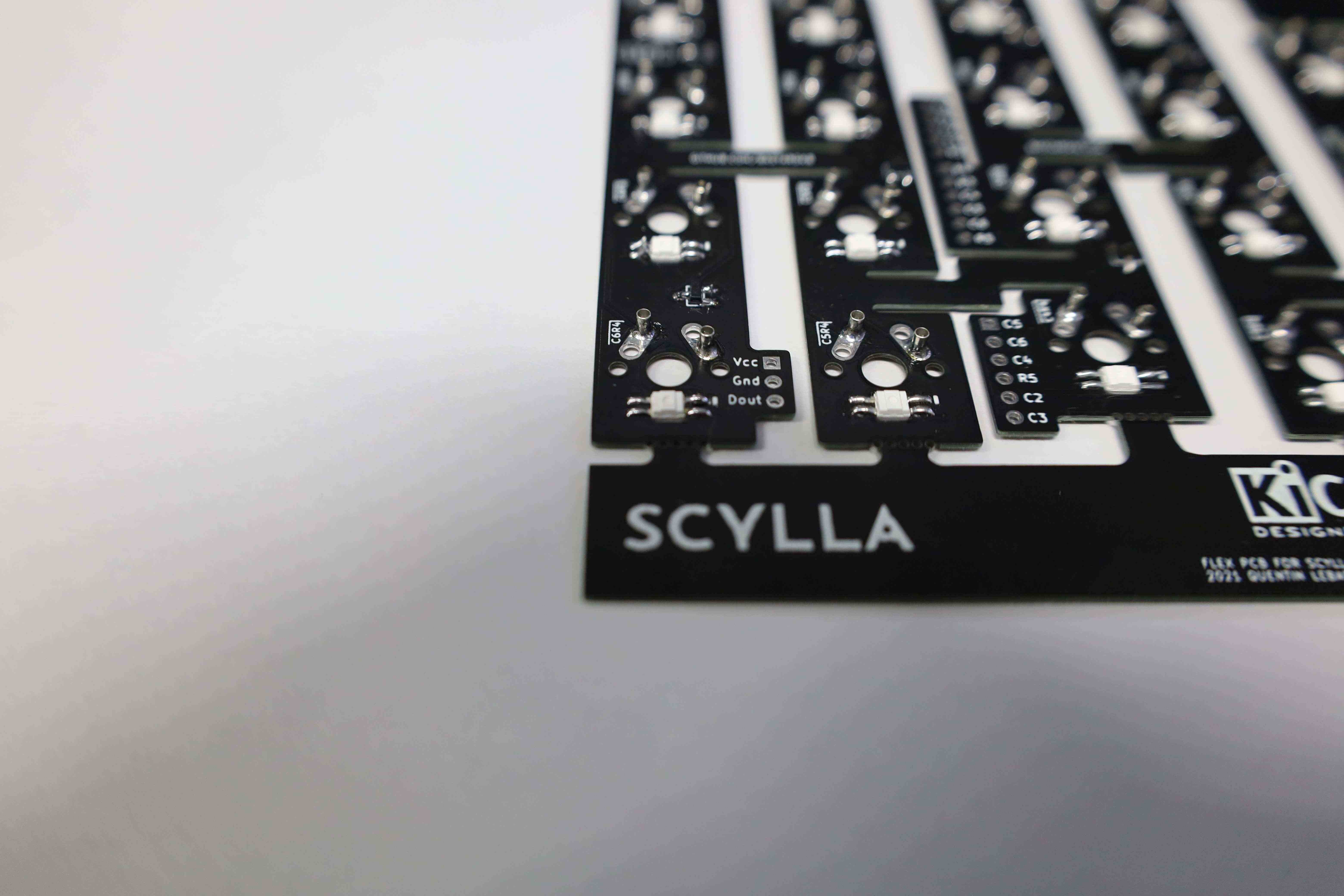
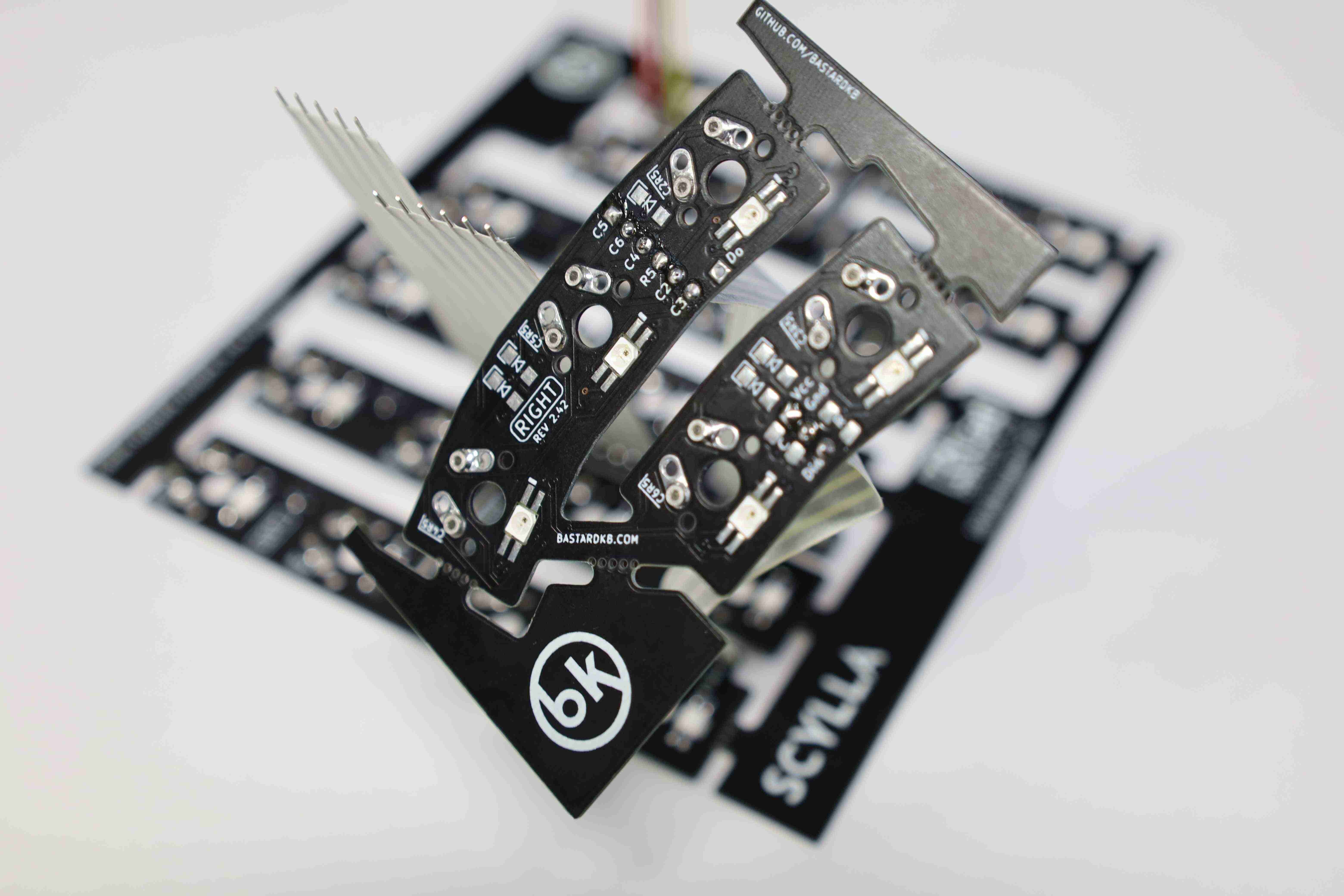
Start by making sure of the orientation: the “Left” label should be the one facing up.
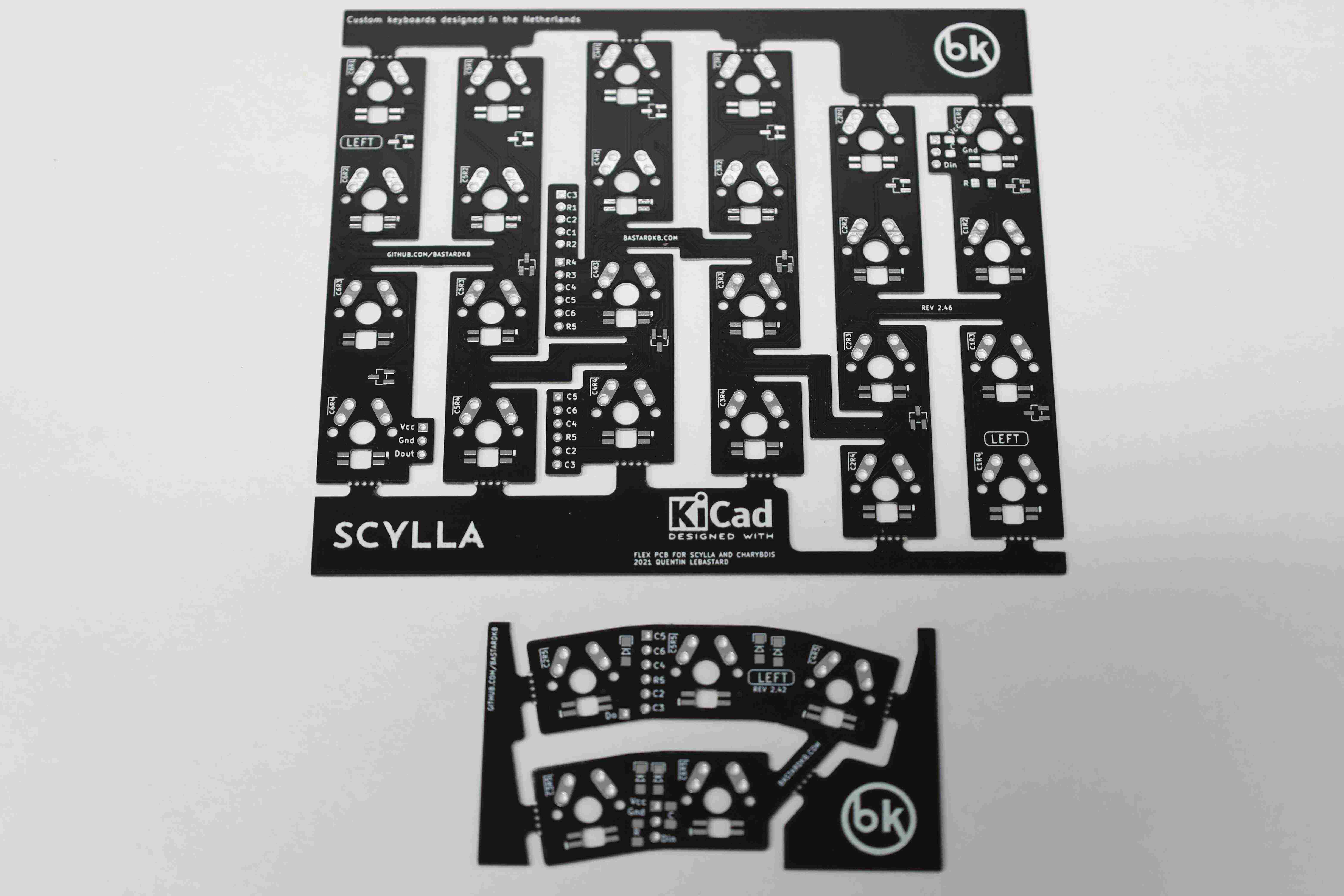
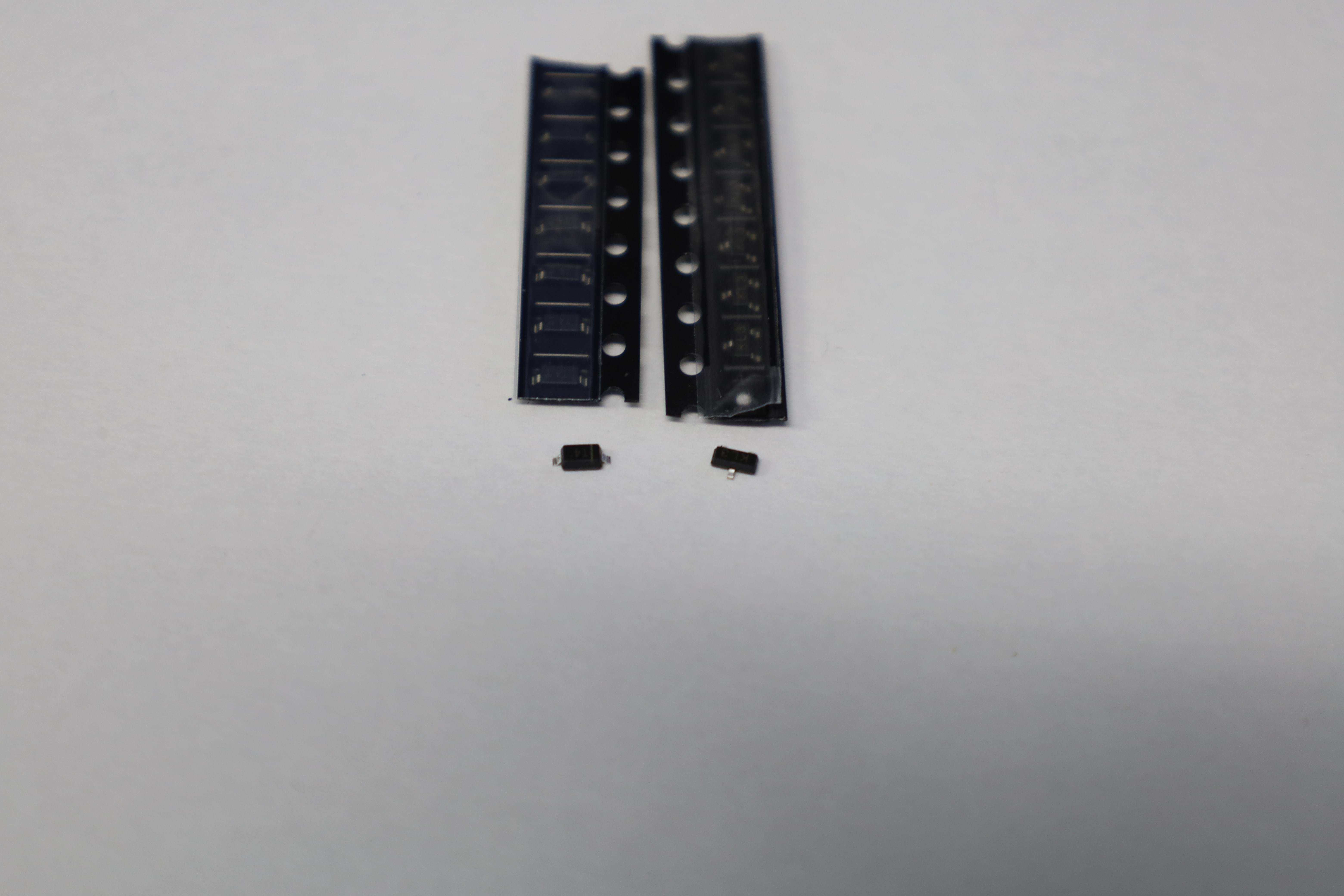
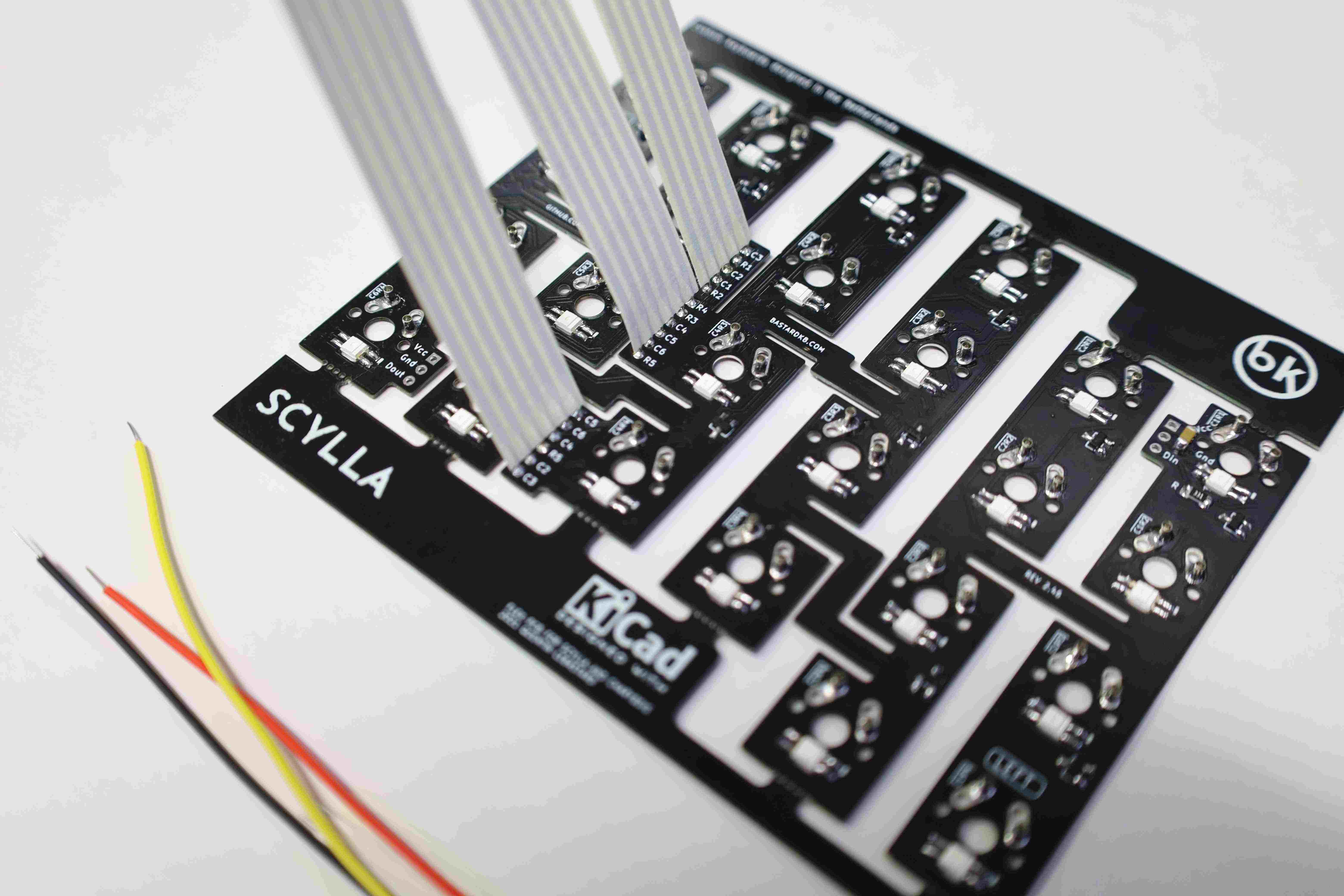
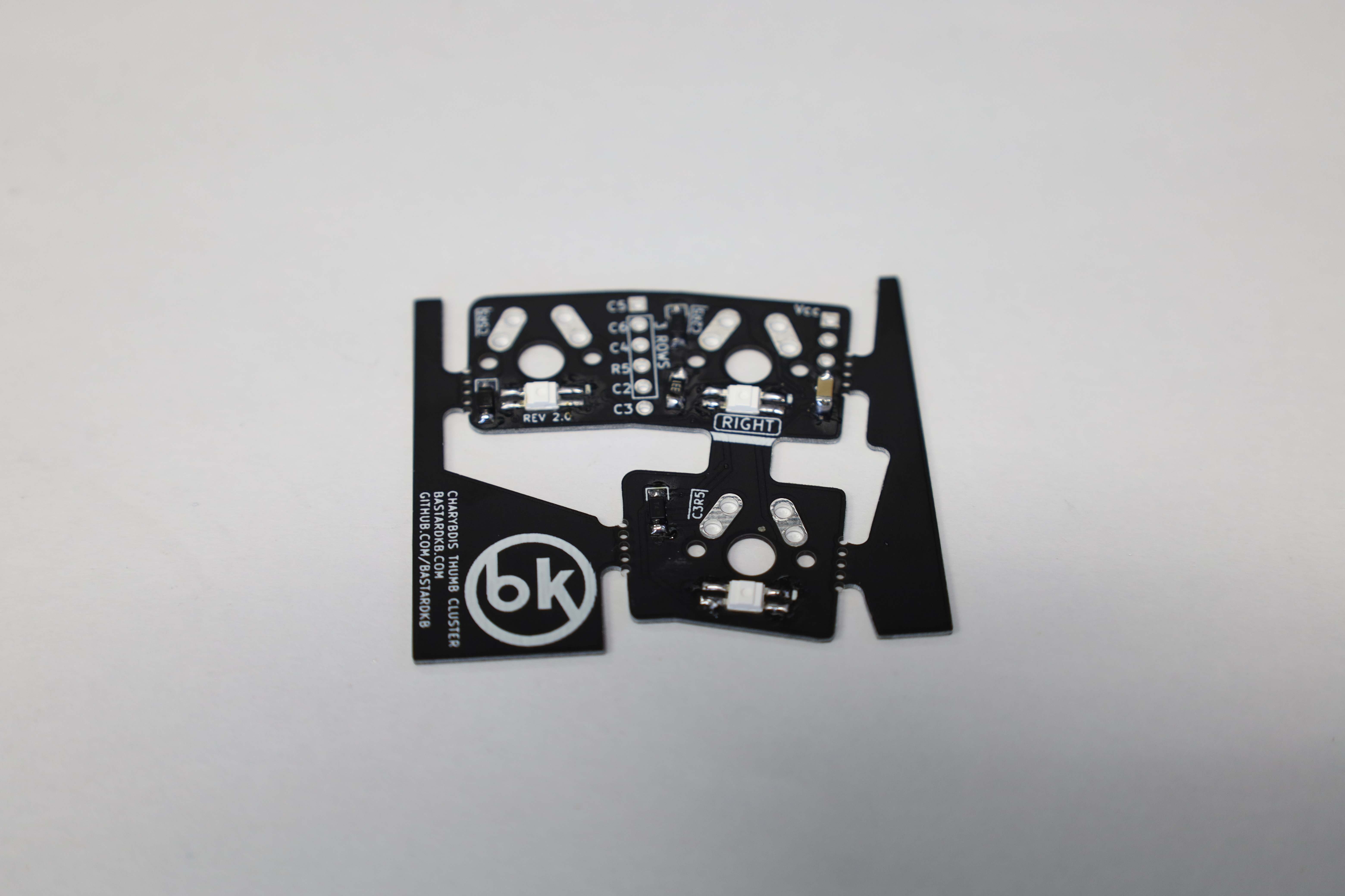
The main PCBs require the three-legged diodes to be soldered at the prepared locations. The two-legged diodes go onto the thumb cluster PCBs. Note that there is a very thin grey line on the two-legged diodes, which has to be aligned with the soldered pad marked with the white silk line on the thumb cluster PCBs.
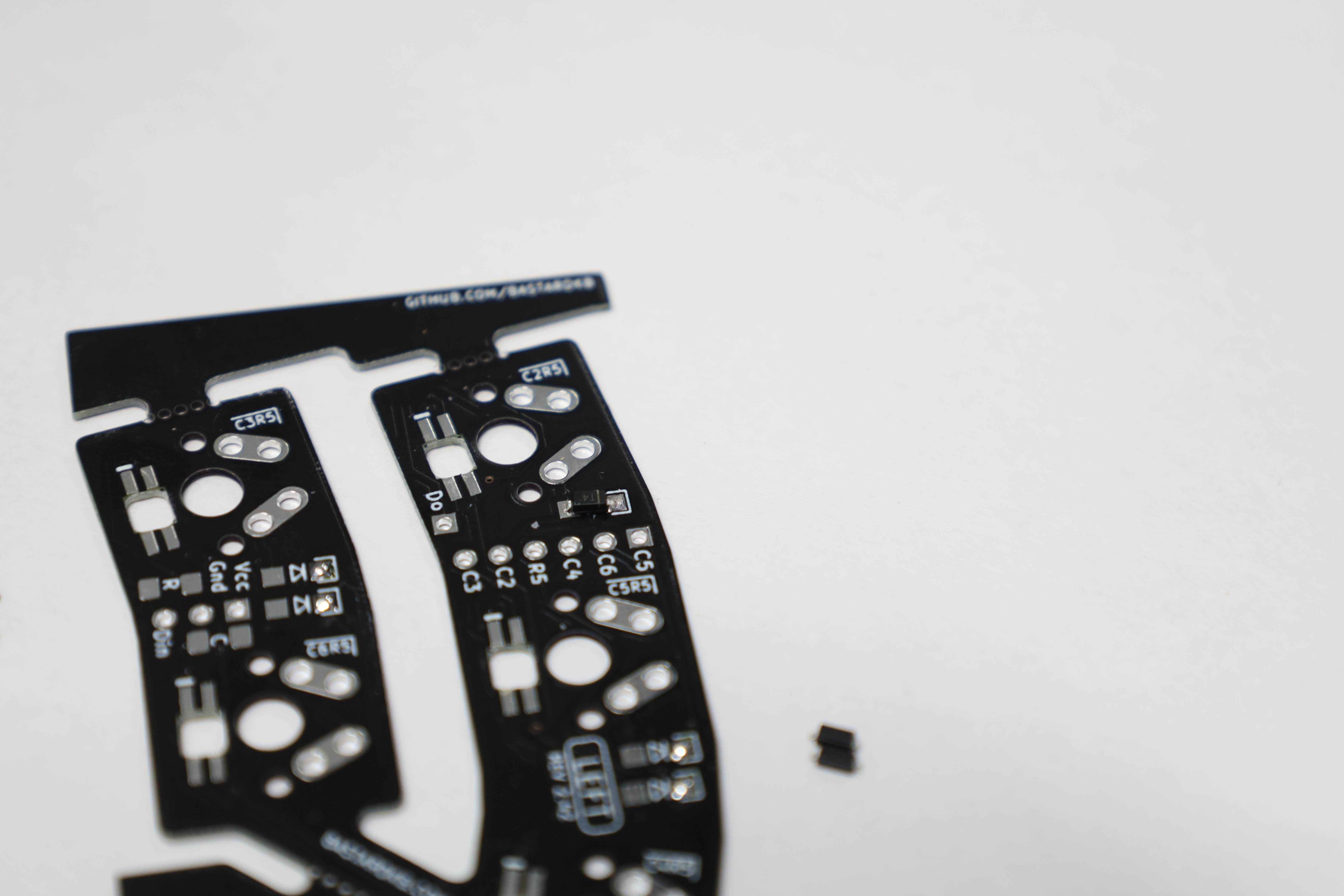
We start by soldering the diodes on the thumb cluster, as a form of warm-up or practice. To do so, we start by applying a touch of tin on one of the pads for each diode location, namely the one with the white silk line.
Next, with a pair of tweezers, we hold the diode down while the marked leg touches the tin on the pad, and gently touch both the leg and the pad so that the tin melts and holds them together. The iron tip is removed first, while the tweezers hold the diodes until the tin hardens. Then, we can release the diode which will be holding well enough to the board so that we can solder the other leg without risking the diode moving around. The left thumb cluster will require five diodes, each one corresponding to one key switch.
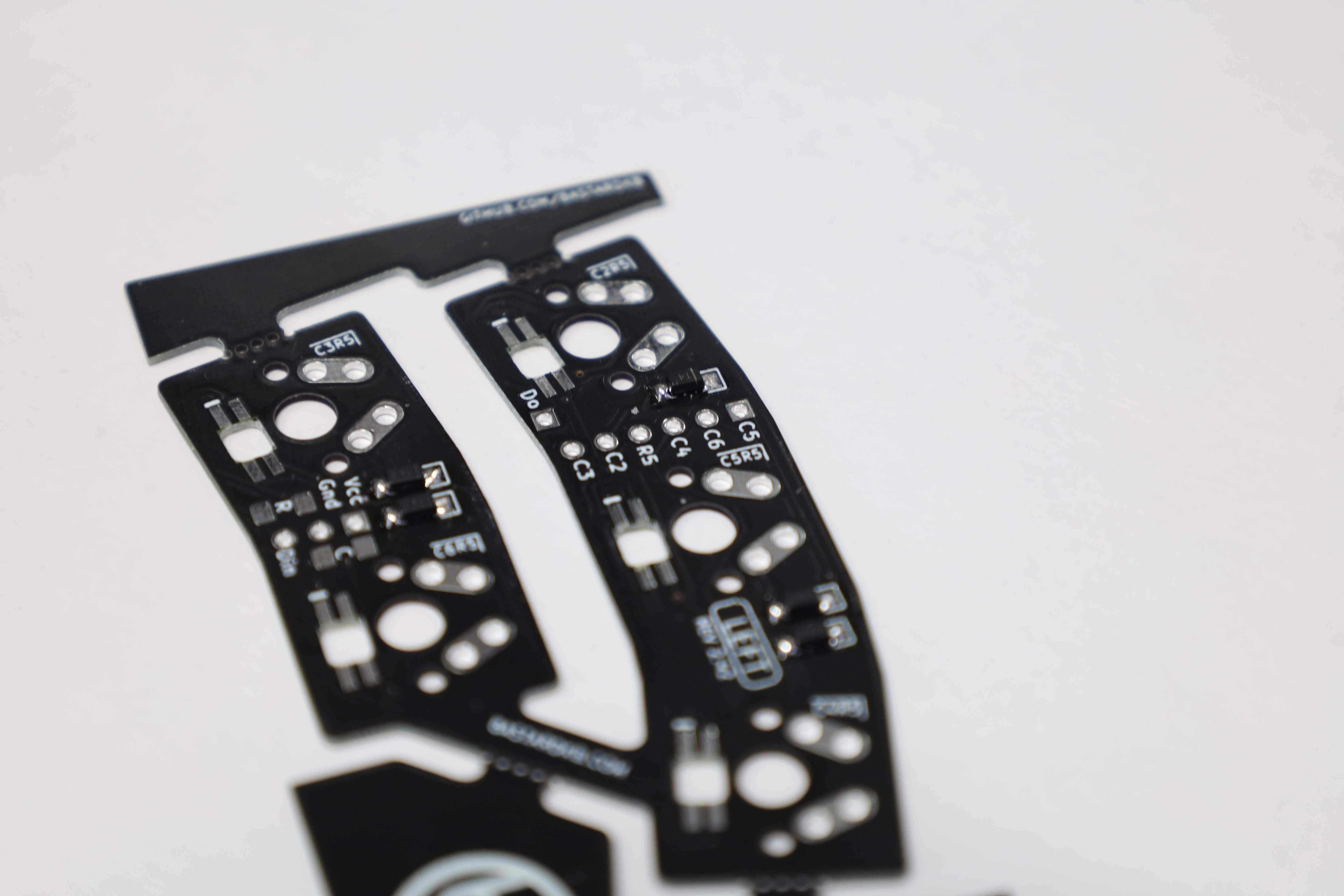
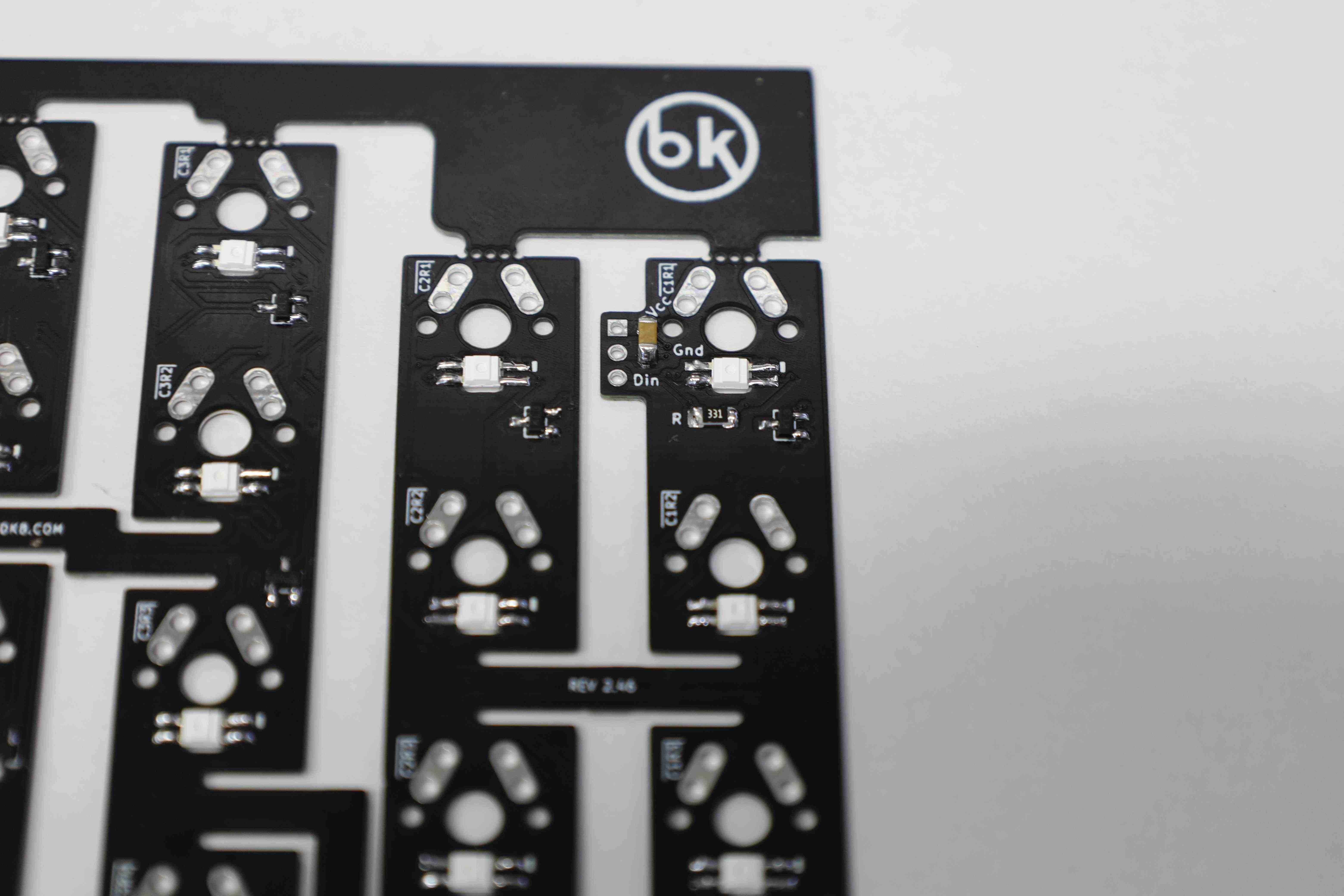
For the main PCB, the three-legged diode makes it impossible to mistake the orientation. We use the same technique to solder down the three-legged diodes, starting with the single leg. The main PCB will take twelve of such diodes, with each one seemingly handling two different key switches (?).

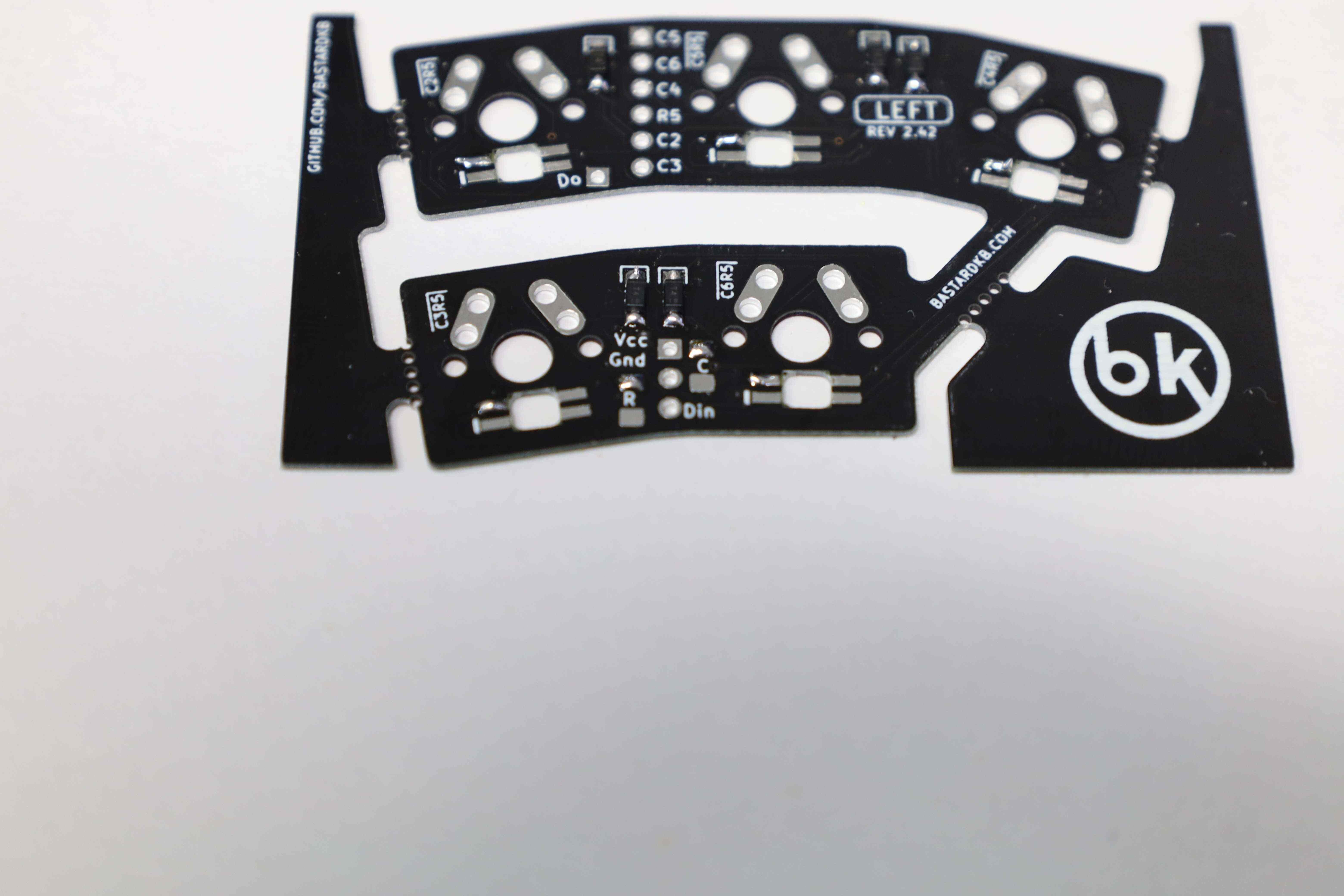
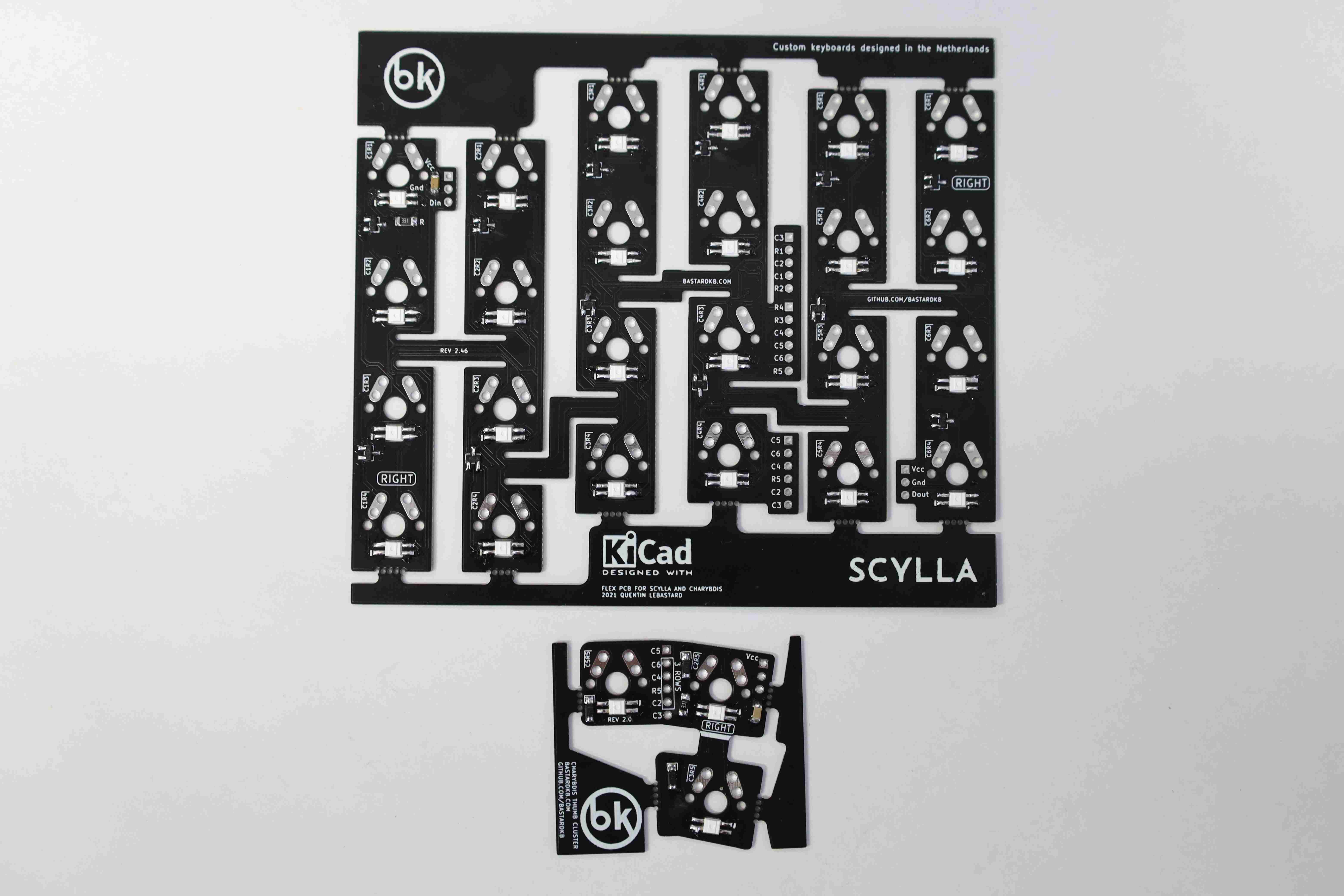
3.2 Installing the RGB components [Optional]
RGB support is orthogonal to the functional aspects of the keyboard, but we gotta move with the trends of the time.
Besides the RGB LEDs themselves, each of the side thumb clusters and main PCBs will require one capacitor and one resistor.

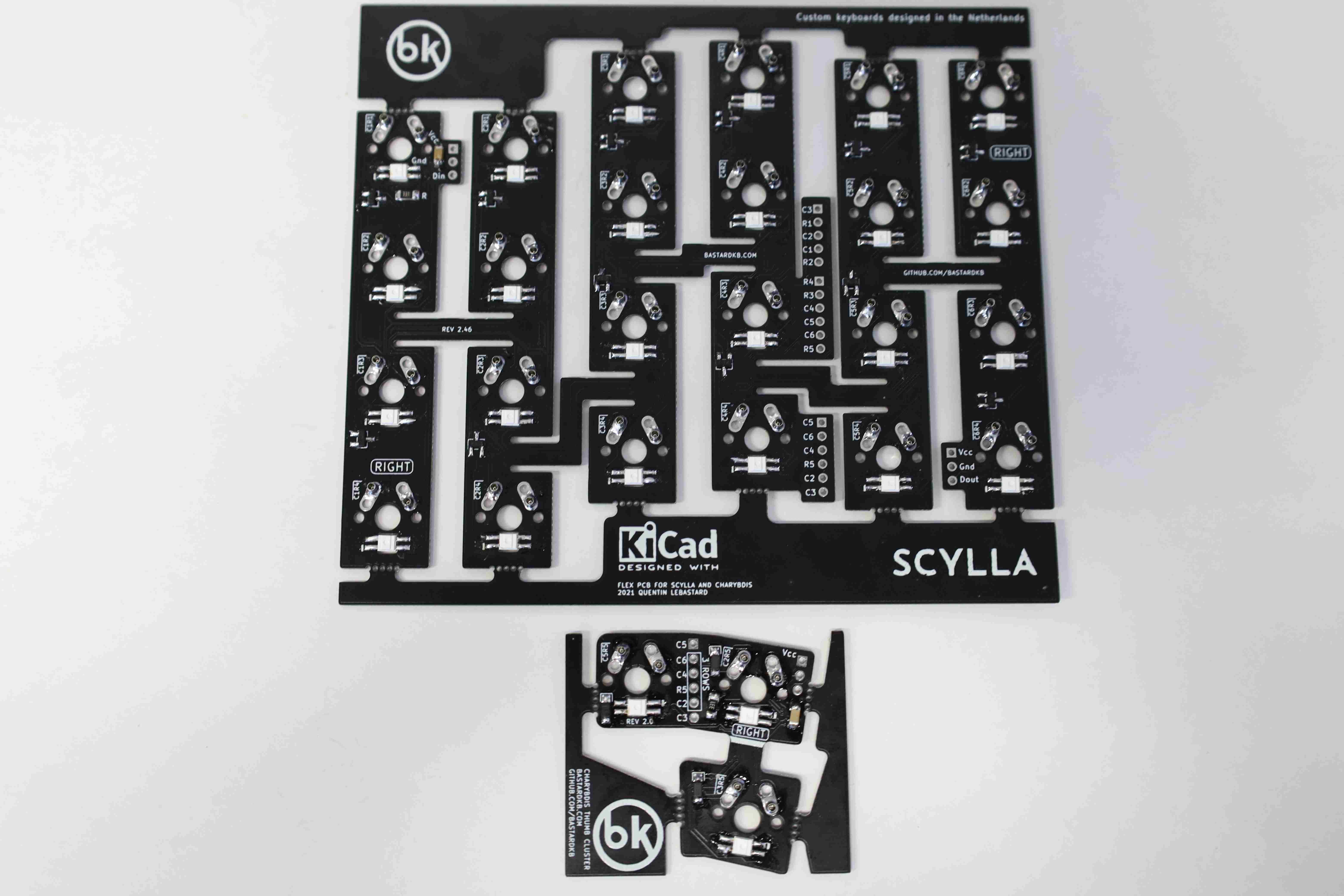
Starting again with the left thumb cluster PCB, the resistor and the capacitor are installed using the same method as for the two-legged diodes. Finally, we add the five RGB LEDs, one to backlit each key.
 {: .text-justify}
The same goes for the main PCB: one resistor and one capacitor, followed by 24 keys.
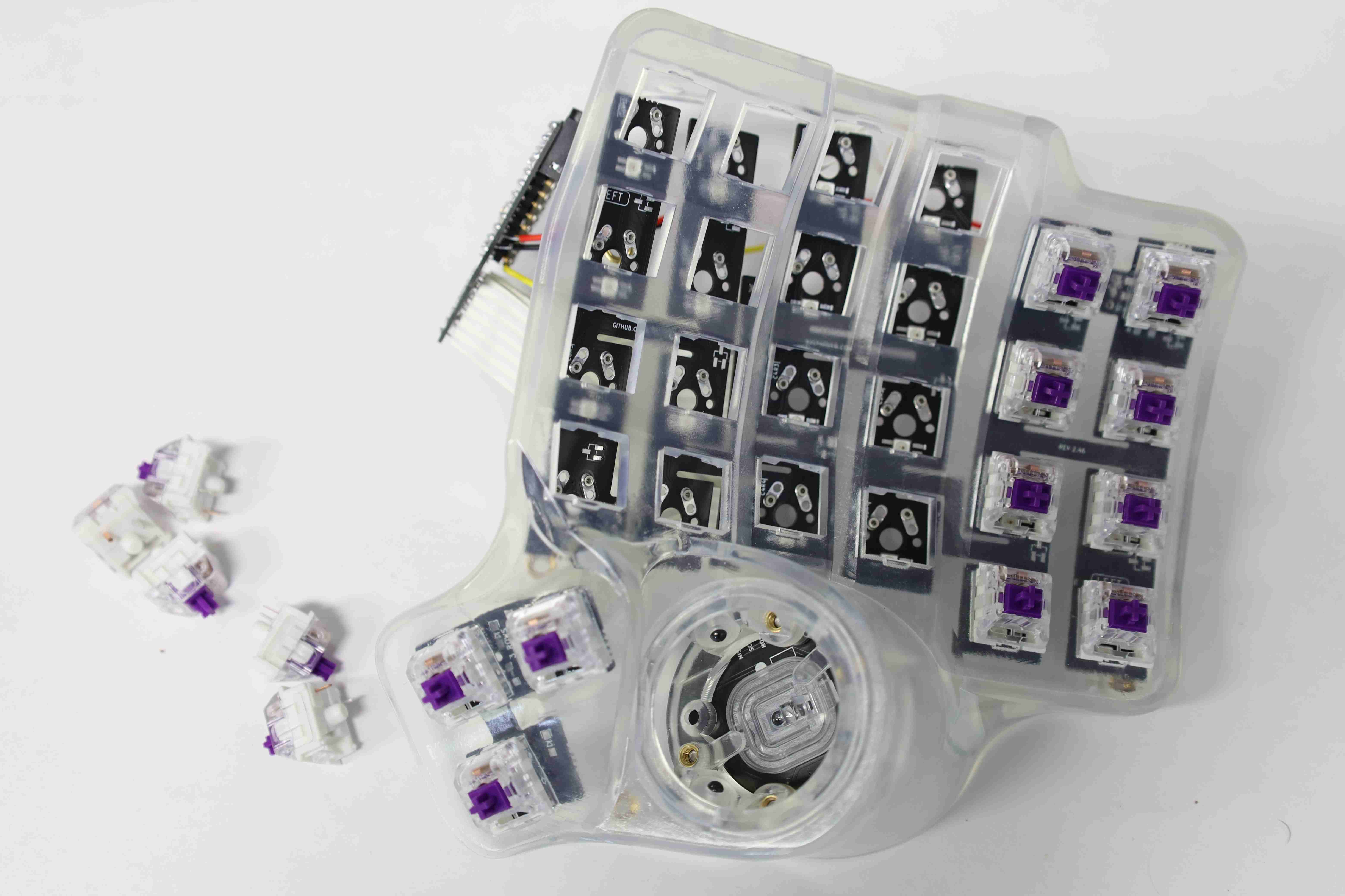
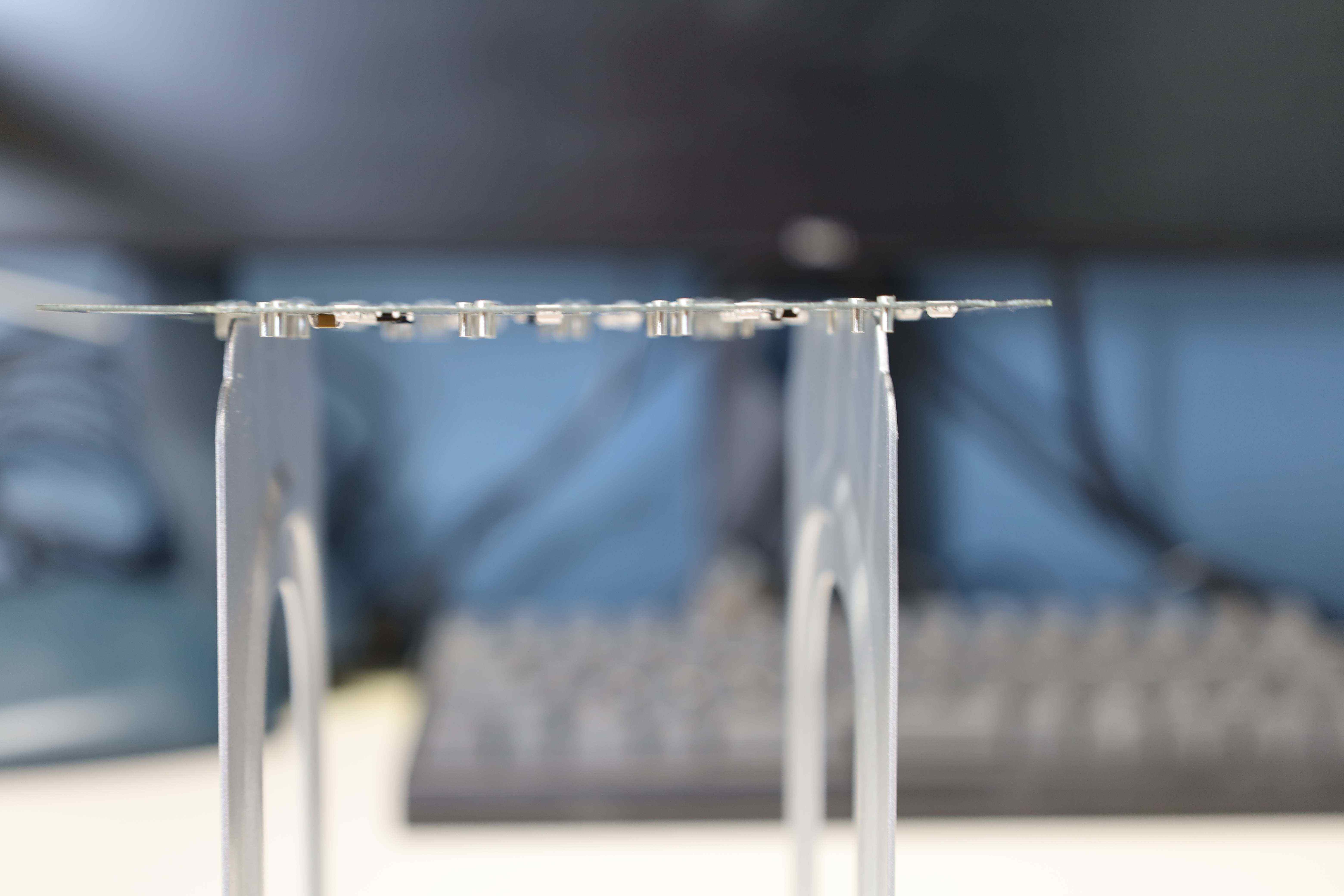
3.3 Installing Mill-Max sockets for hot-swap [Optional]
This build uses Mill-Max sockets to allow hot-swapping of the key without even disassembling the keyboard case at best. At worst, it allows changing the key switches without soldering.
After suspending the PCB while keeping the bottom part accessible, the Mill-Max sockets are inserted according to the key switch legs layout.

After this step, there was a little bit of experimentation to determine the best way to solder the sockets that will allow the key switches to fit on the PCBs as flush as possible. Otherwise, different keys would have different heights relative to the board, which would be hardly ergonomic.
1. For the first method, tin up all the sockets to the board so that they hold to it, allowing us to flip the board with ease. Once the board is flipped, solder the sockets from that side while pressing hard on the PCB to make sure the sockets are flush with the table surface. The caveat with this method is that if not pressed hard enough, the sockets might not be flush with the PCB from the top perspective. Another one is that it requires two soldering steps, which will likely result in an above-average amount of tin spent.

2. For the second method, once the sockets are installed in the holes, find some hard enough cardboard to place on top of the PCB and sockets, then hold it tight and flip the board to access the bottom side. From there on, solder the sockets. While this method is cleaner than the first one, it might be challenging to flip the board in the first lace. Also, while soldering, rash handling dislodges the sockets that are not yet soldered and requires flipping the board and inserting the sockets again. This can result in lost sockets too.
The same process for the Scylla left PCB.

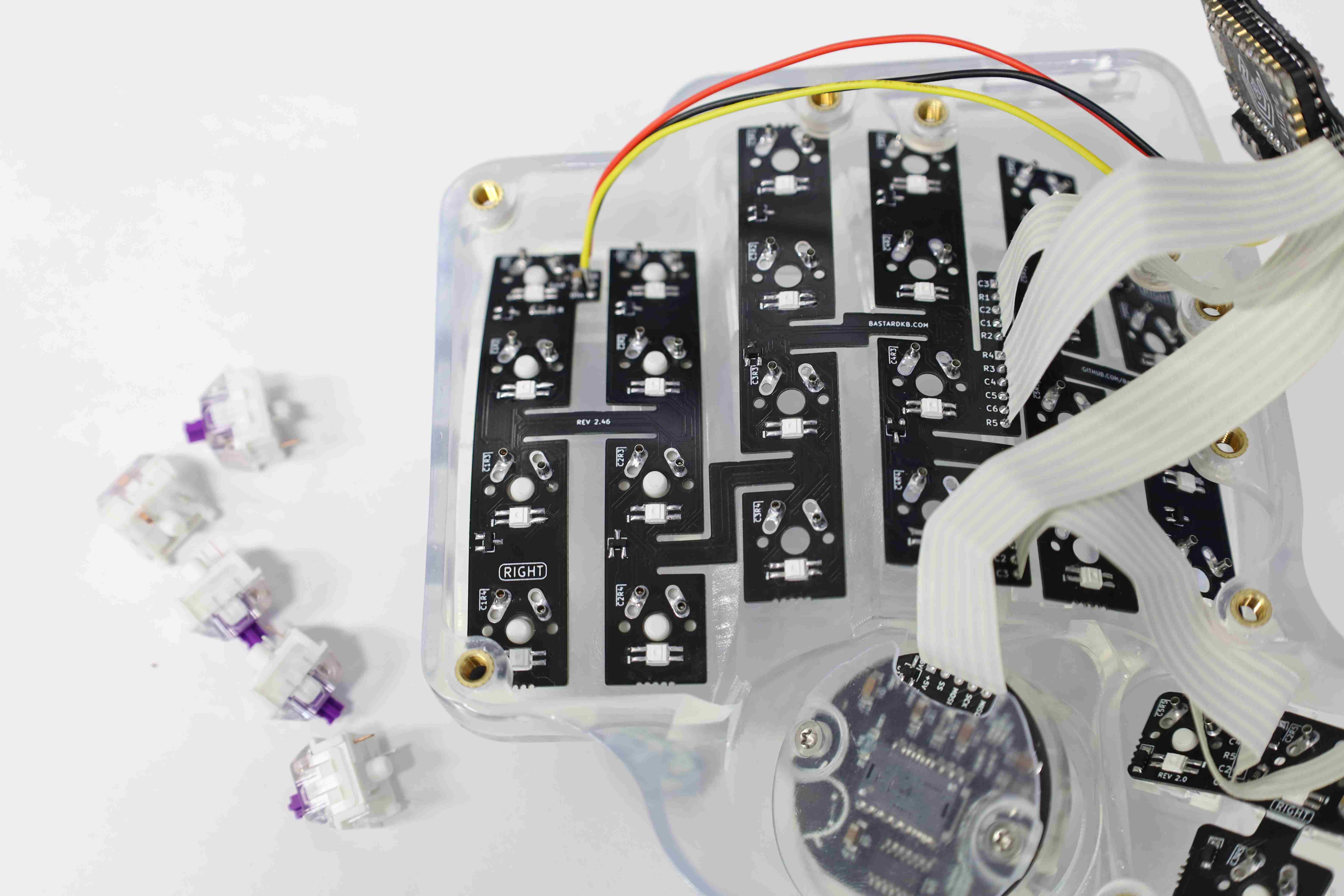
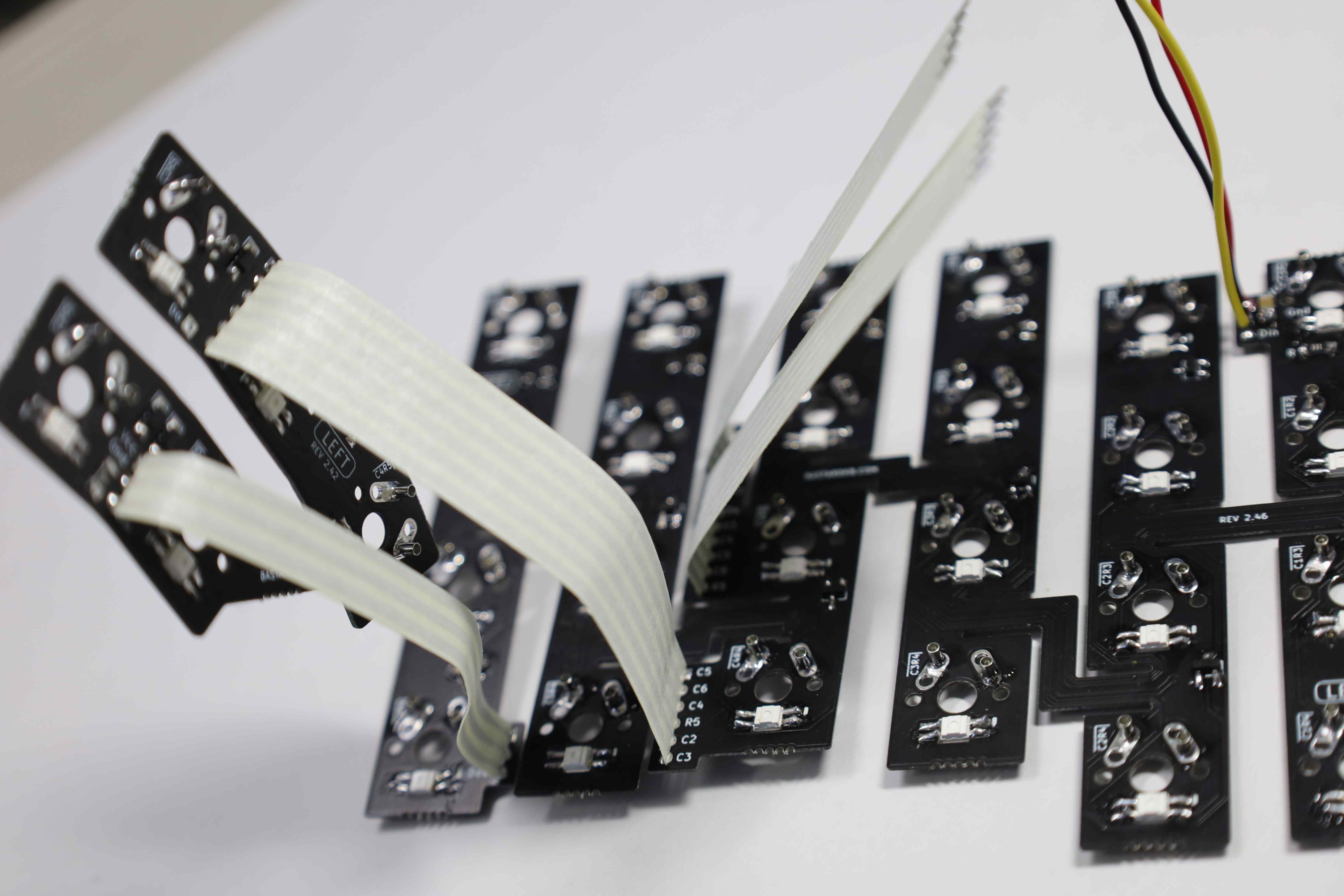
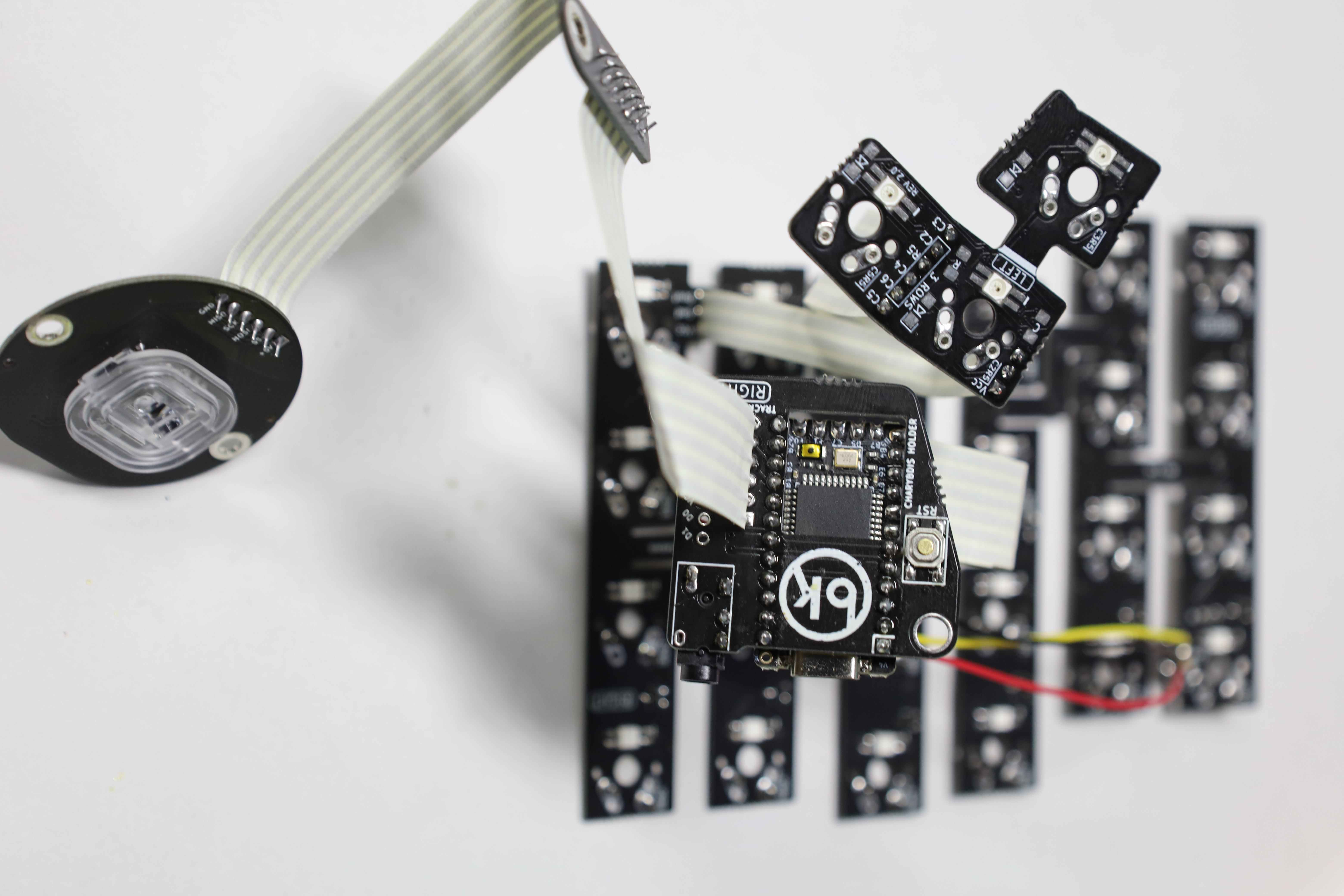
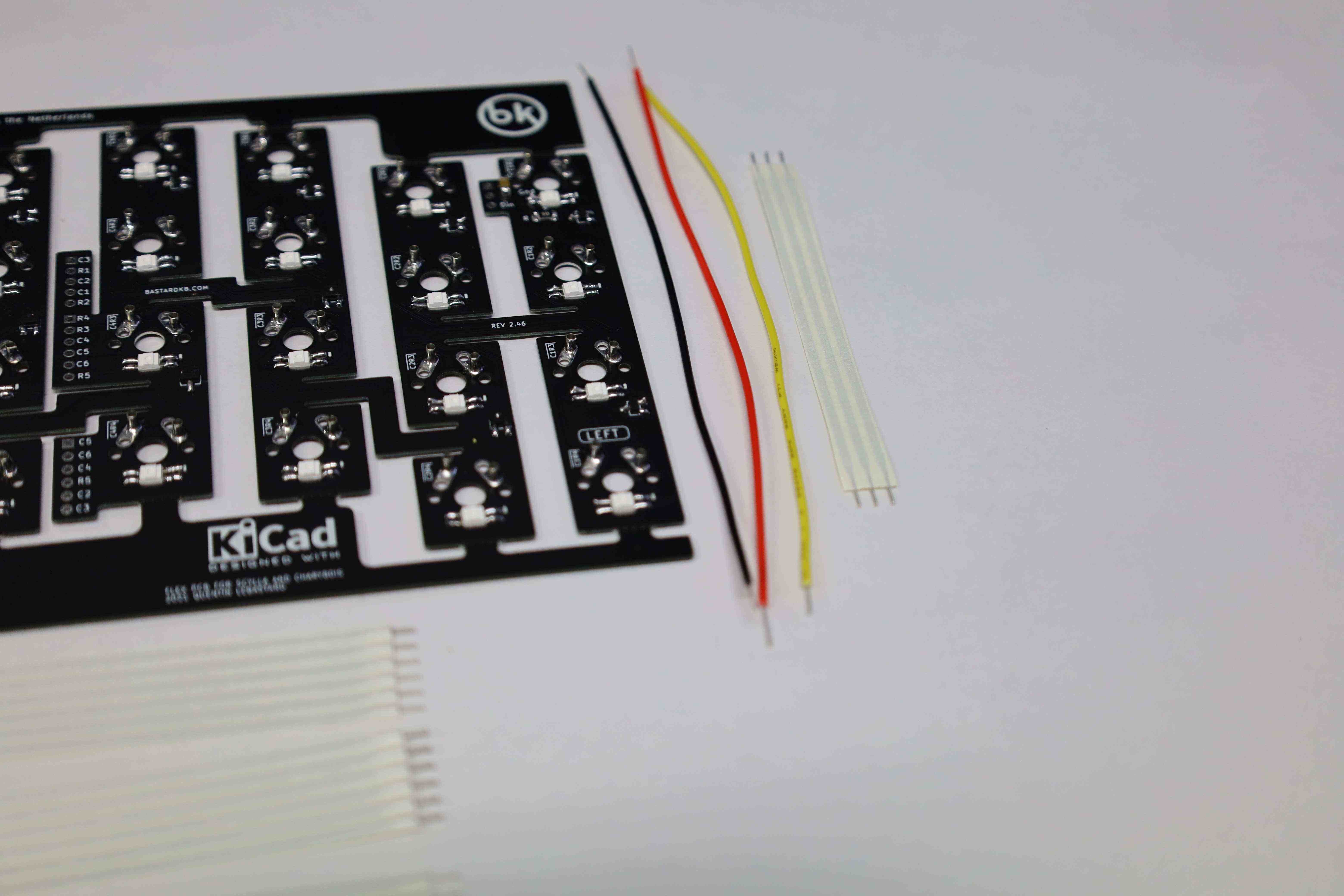
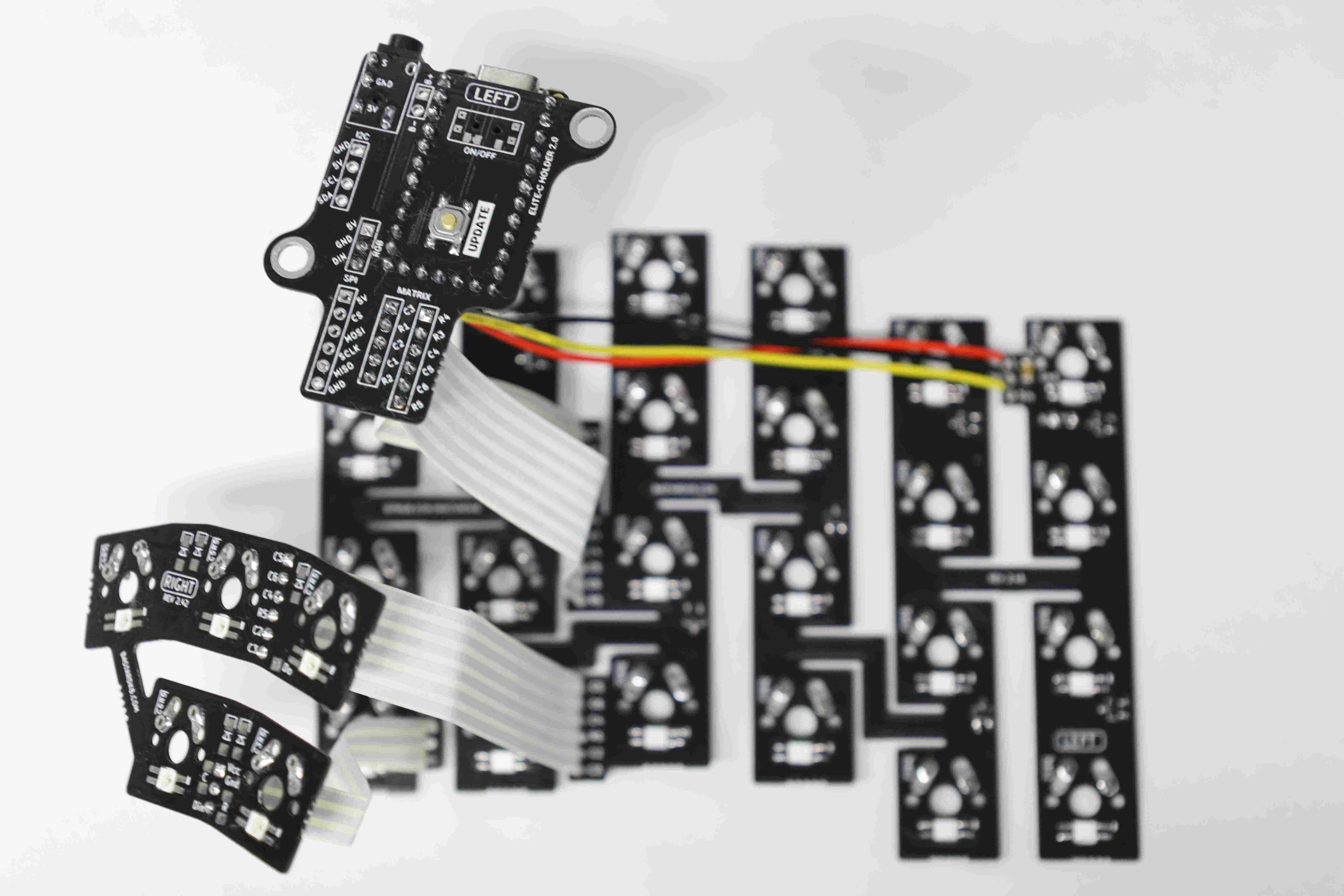
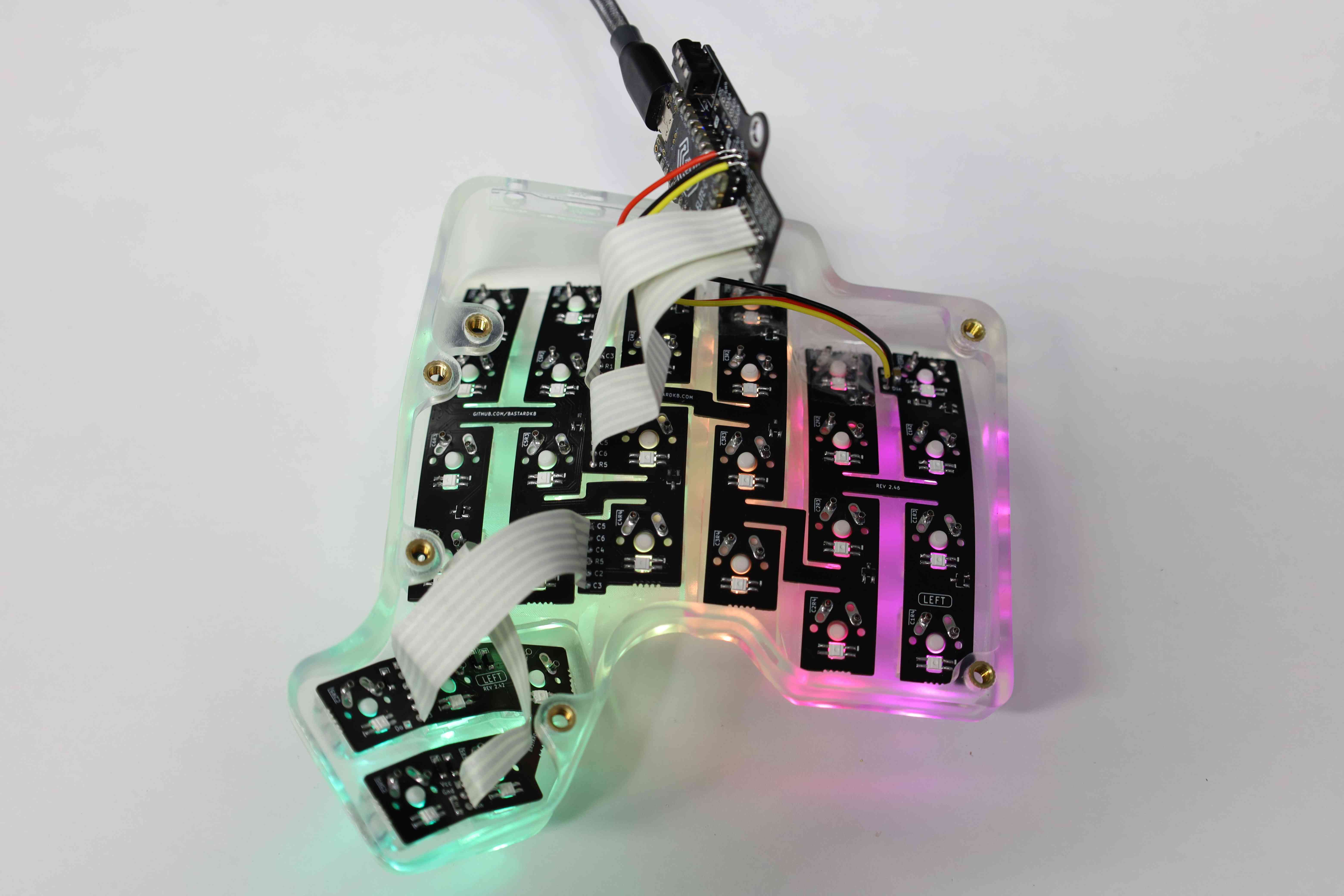
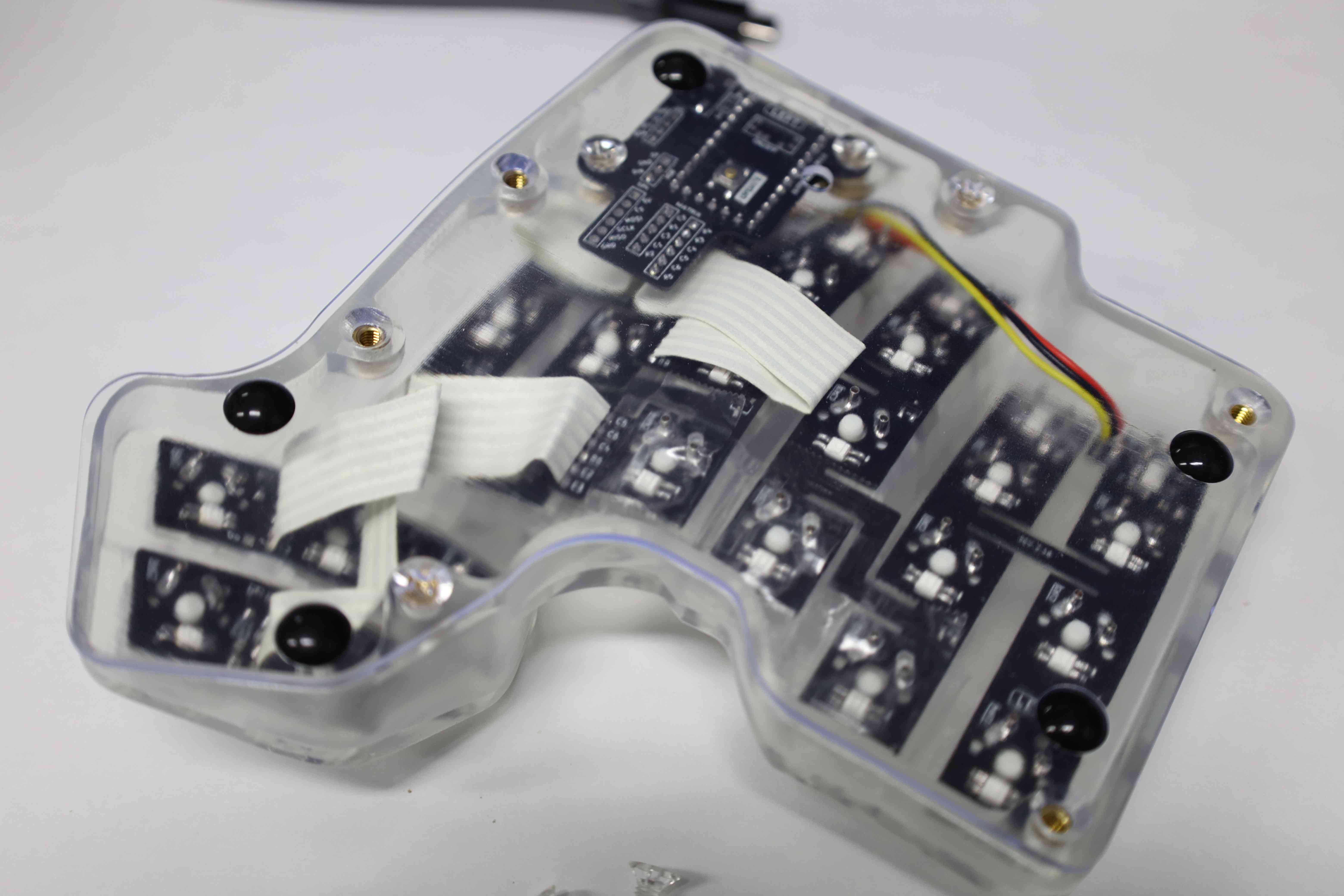
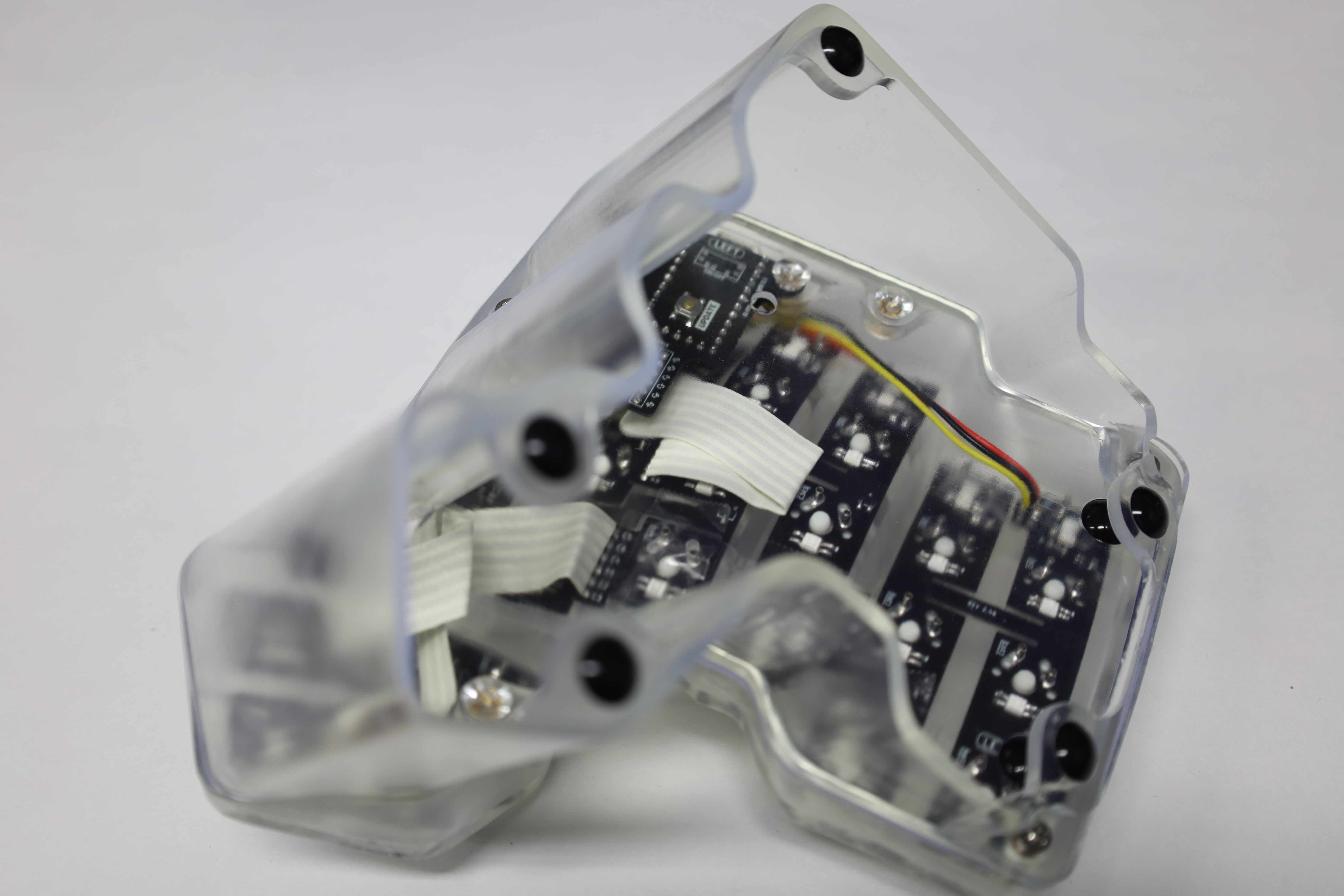
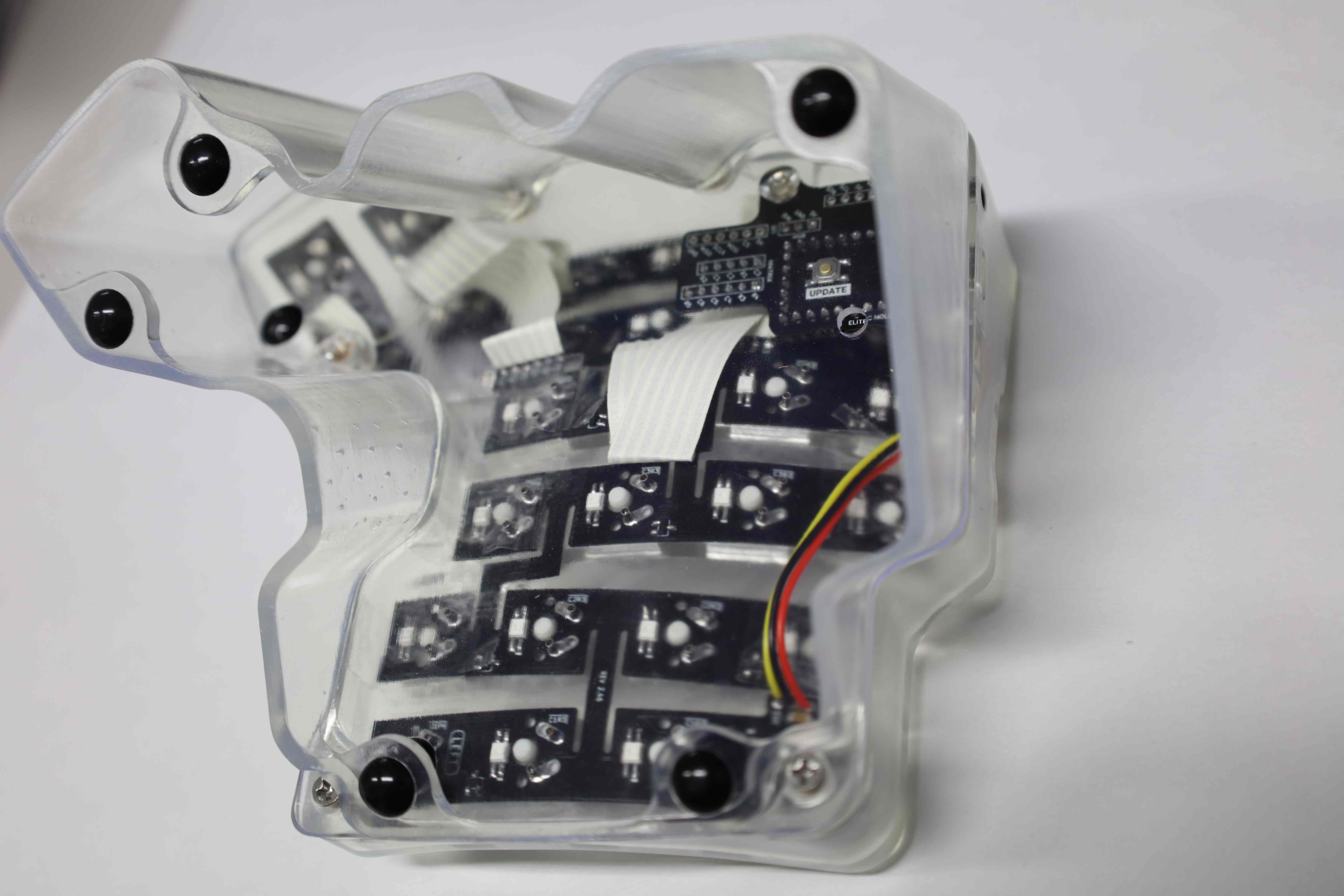
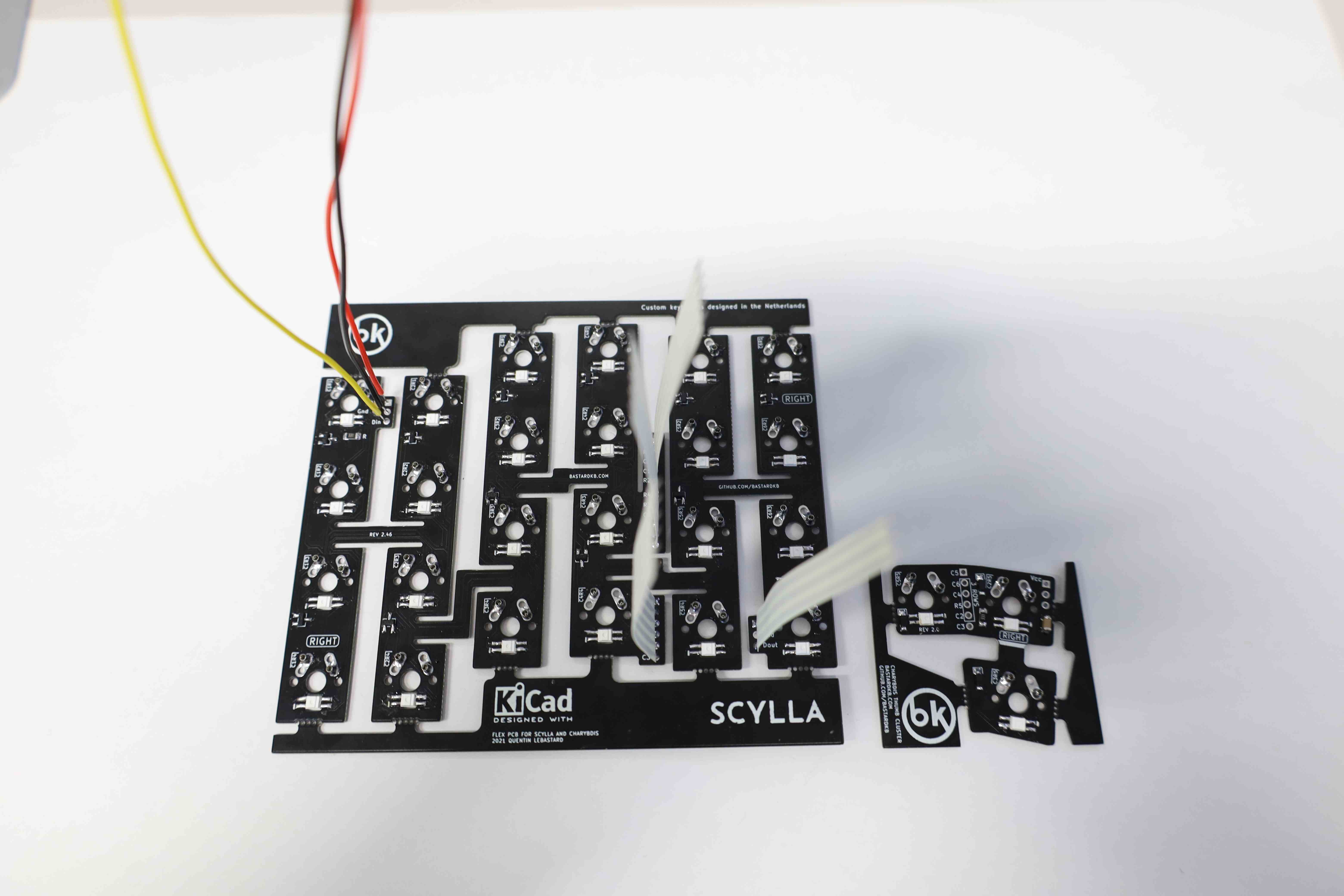
3.4. Ribbon cables and RGB cables
Next, the ribbon cable that connects the main PCB to the thumb cluster, as well as the MCU, can be installed. This step can also be tied with the RGB cables install as well, although RGB is an optional feature.
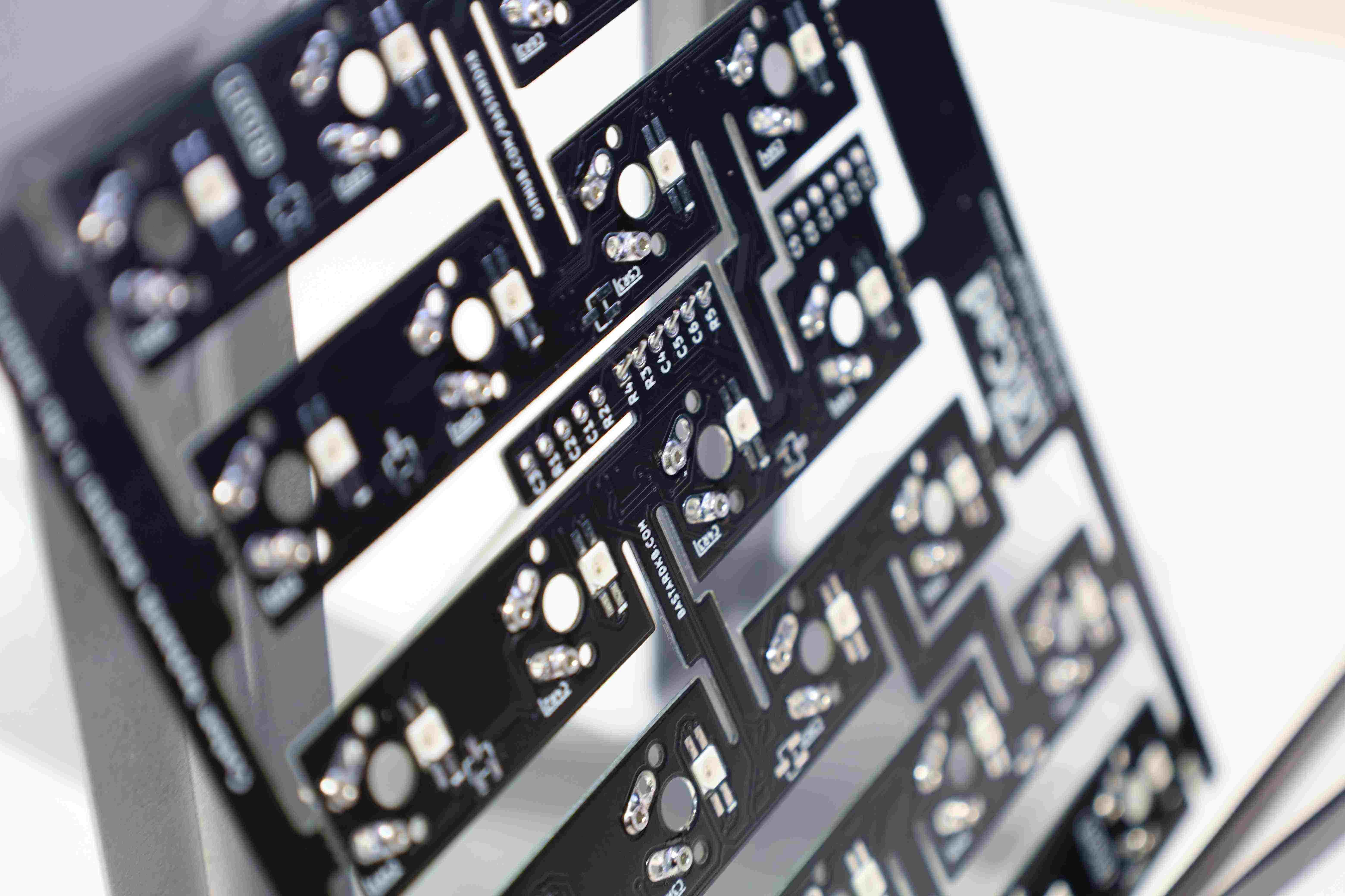
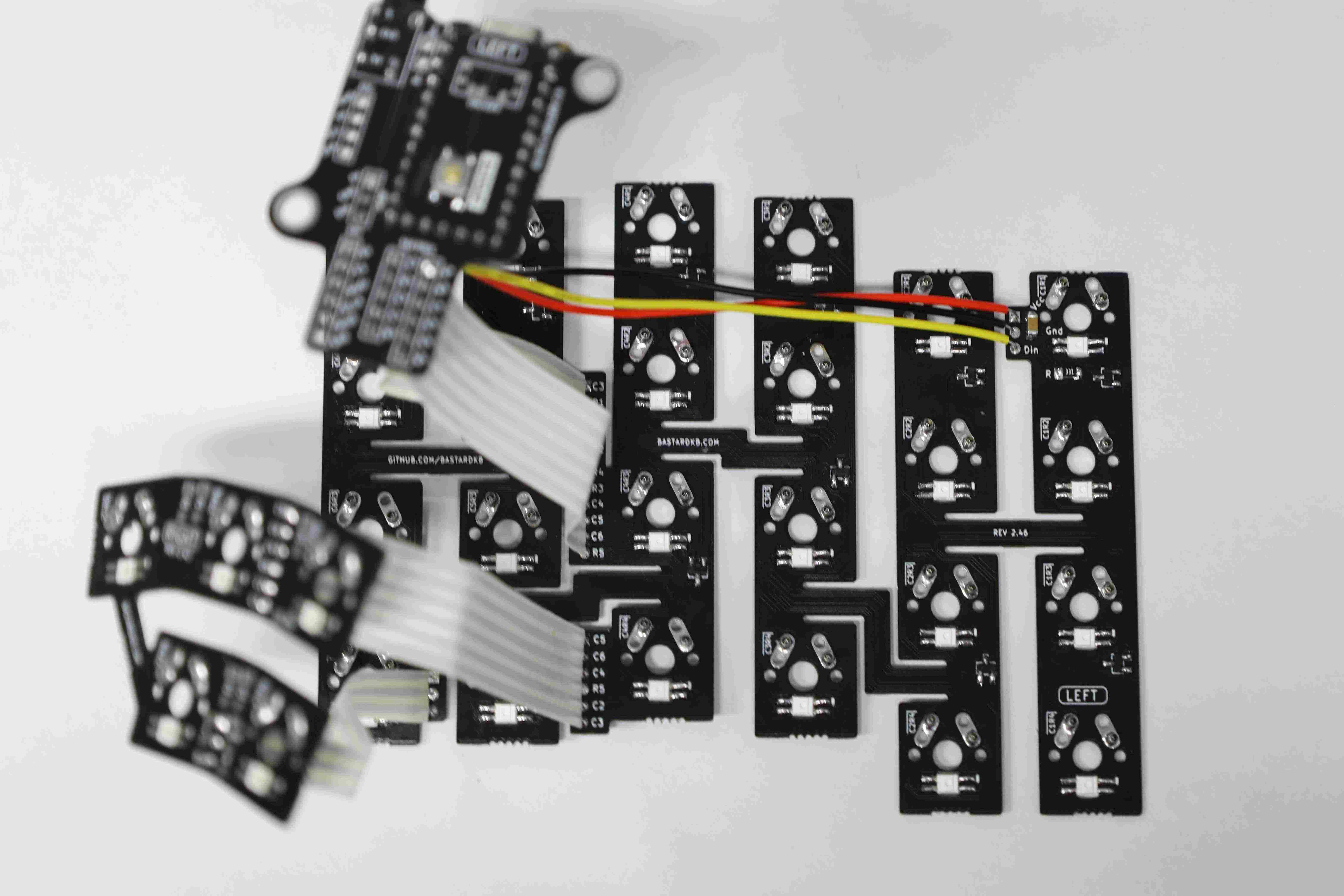
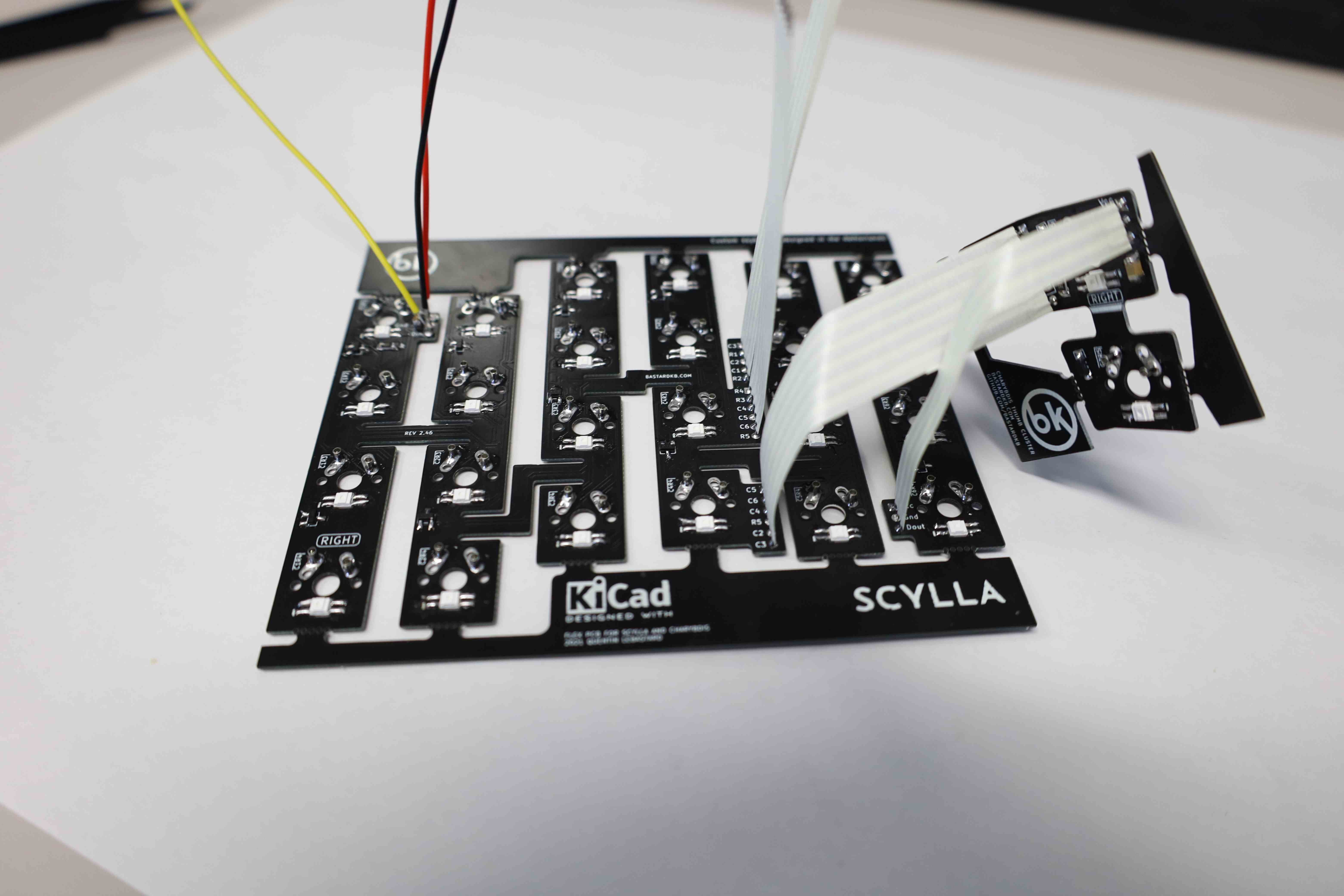
The building kit came with a band of ribbon cables that had to be cut into smaller bands of two sets of 6-6-5 wires, as shown in the picture below.
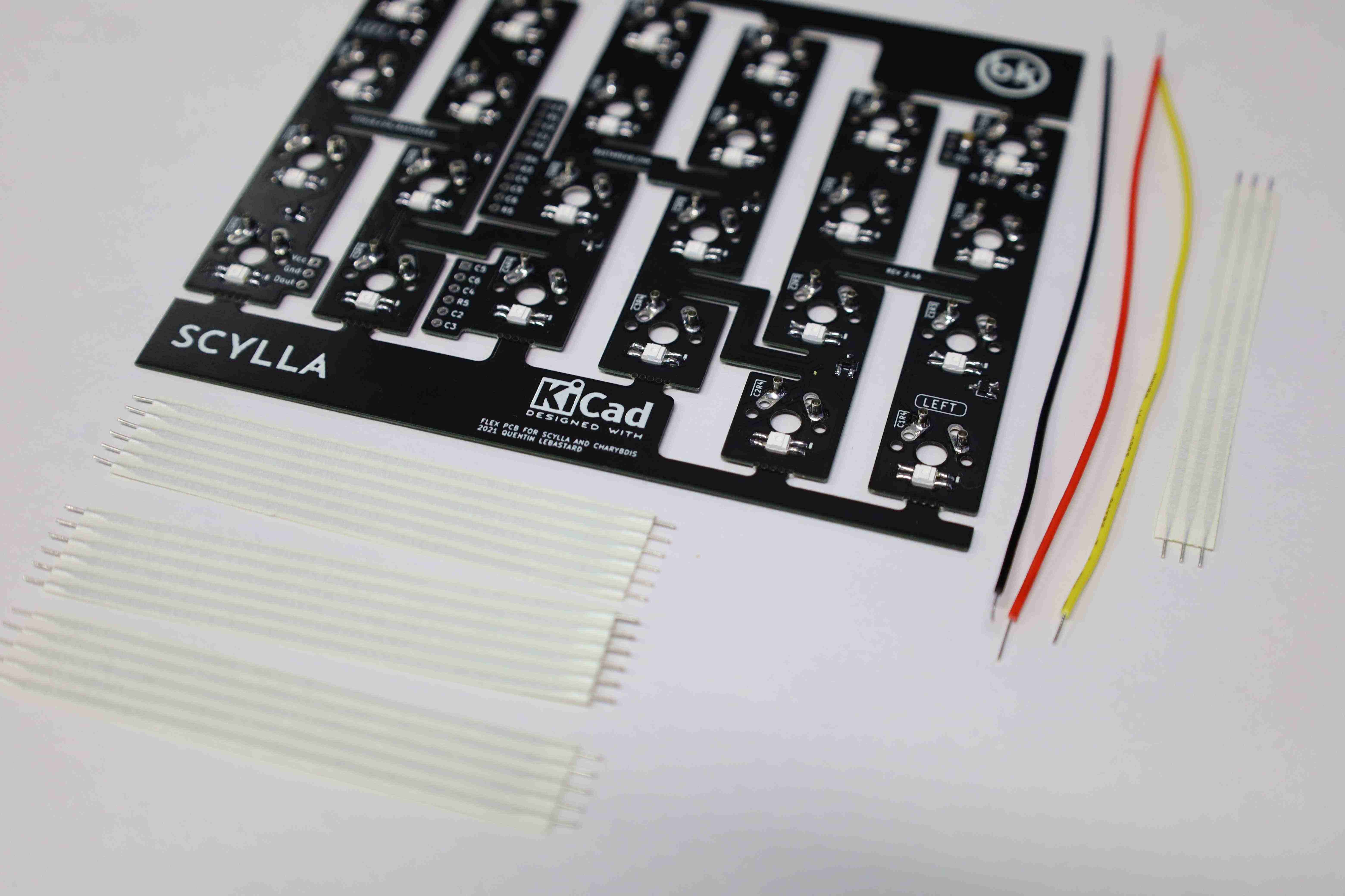
While it is convenient to use those ribbon cables during the build, nothing stops one from using any other cable type, as long as it conducts an electrical signal. Go crazy.
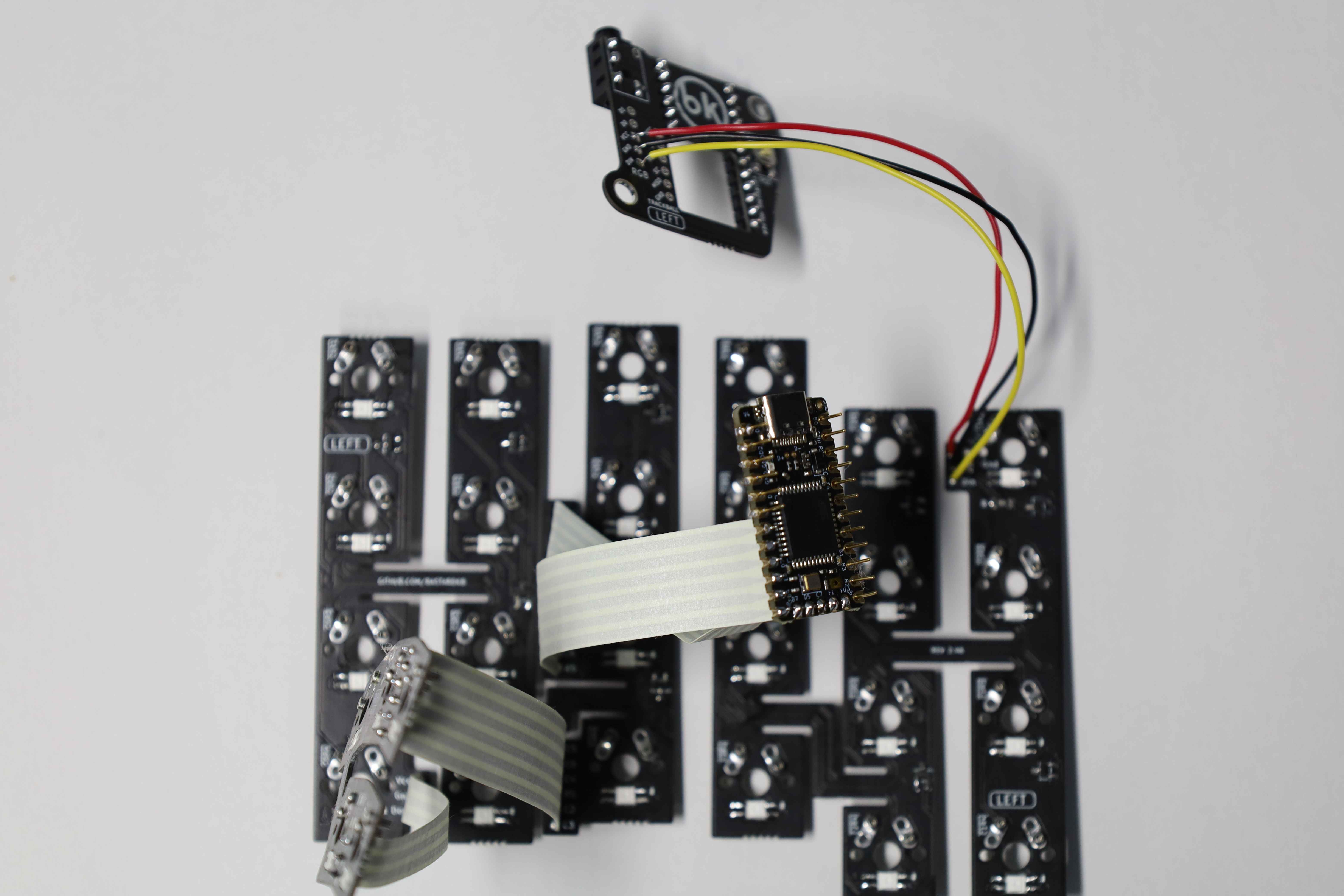
For a given side, the RGB cables come in two sets.
- a set of black (GND), red (VCC or 5V), and yellow (DIN / DOUT) to connect the PCB to the MCU
- and a set of ribbon cables with three wires to connect the main PCB to the thumb cluster one.
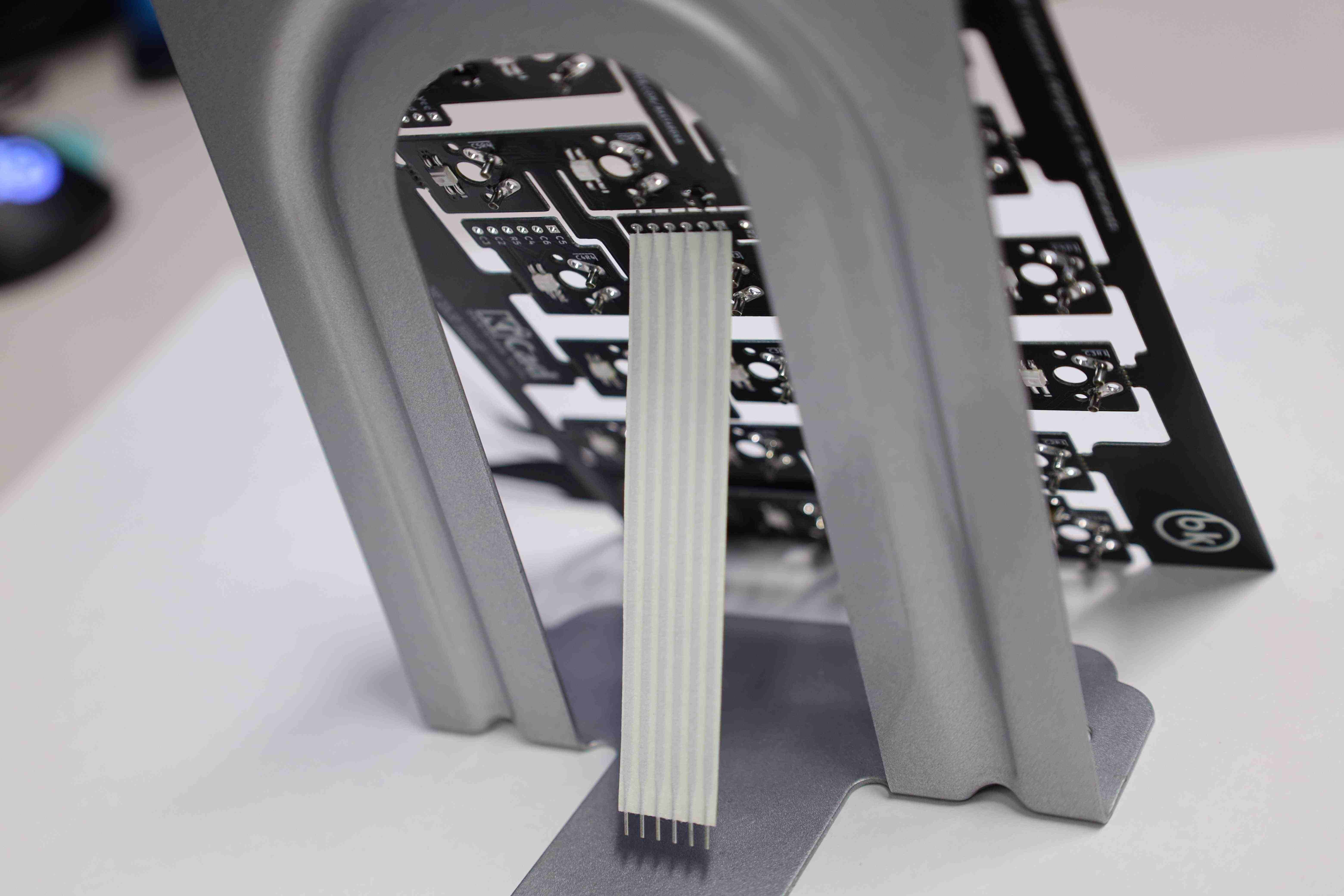
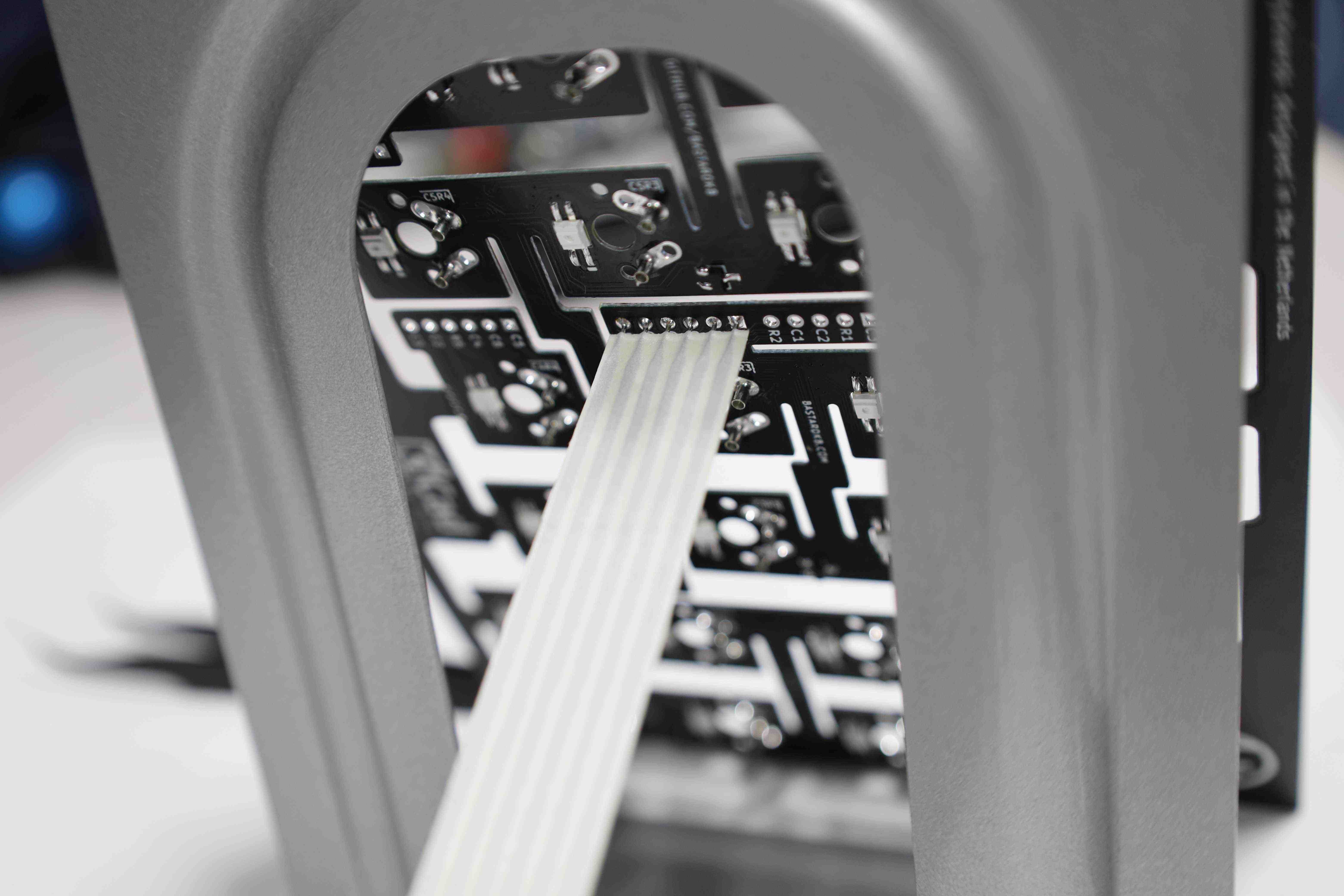
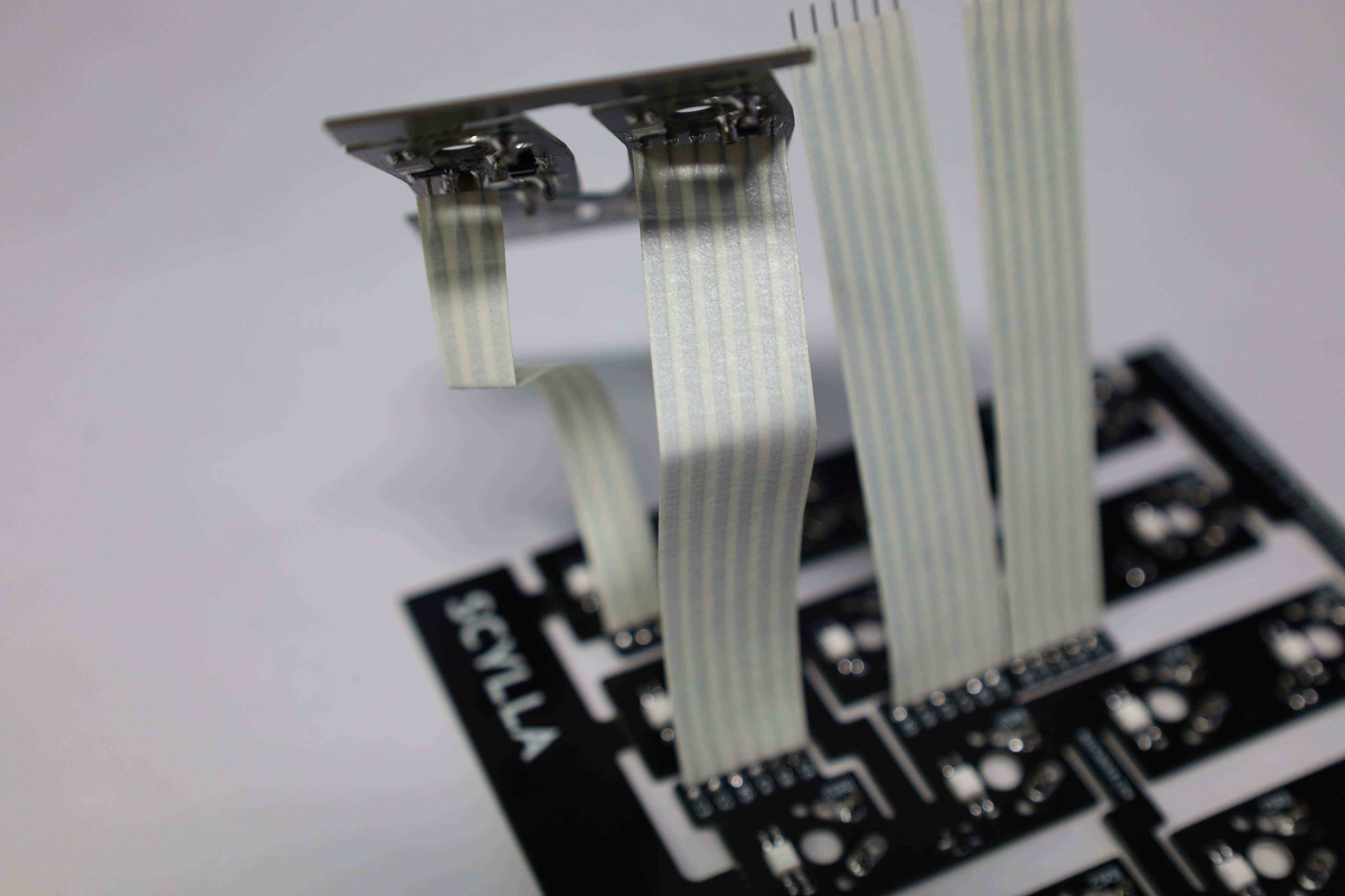
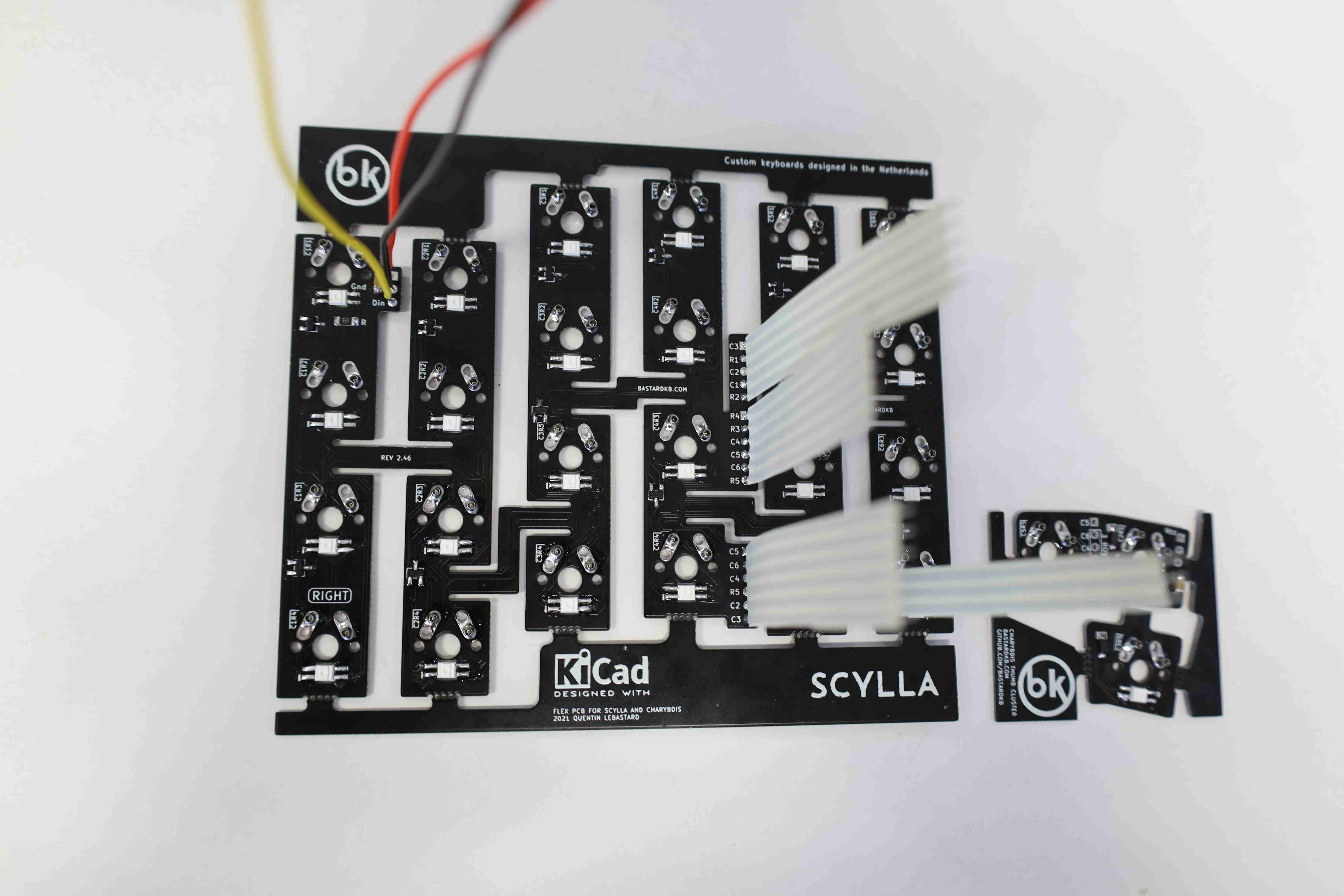
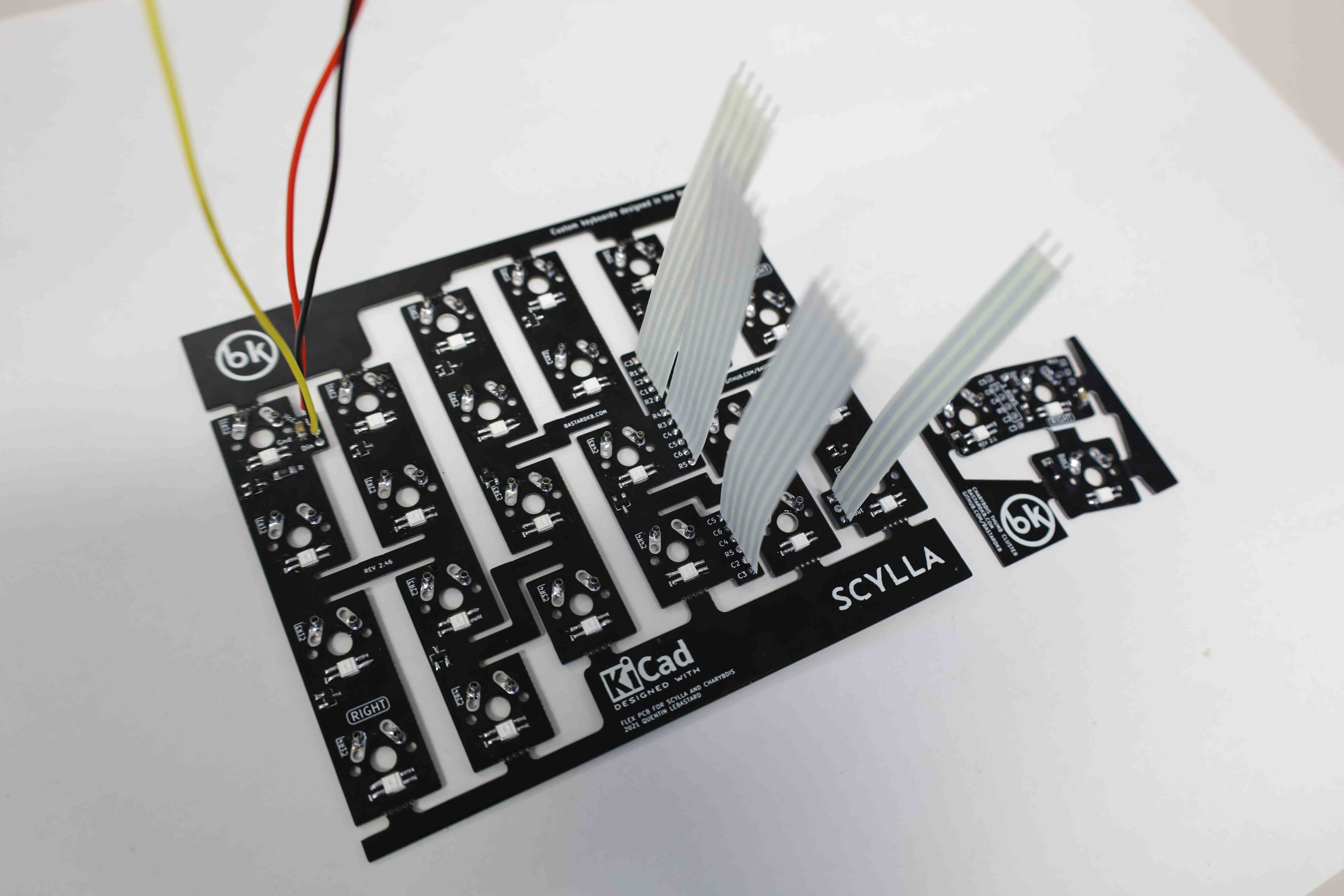
If building alone, it might be tricky to keep the ribbon cables in place while doing the soldering, so improving a support structure might come in handy. (In case one does not have those octopus-like helper clipping hands.) In this case, this is done using book-holding stands. In any case, cable installation is quite straightforward:
- match the number of wires in the ribbon cable with the number of wholes on the board,
- insert the ribbon cable from the backside (side opposed to the one where the switches will be plugged)
- tin one of the wires to its hole on the board while aligning the other. Once the tin hardens, the other wires can be soldered painlessly
- trim the sharp side of the wires to make the whole as flush as possible. Then the process is repeated for the other ribbon cables.

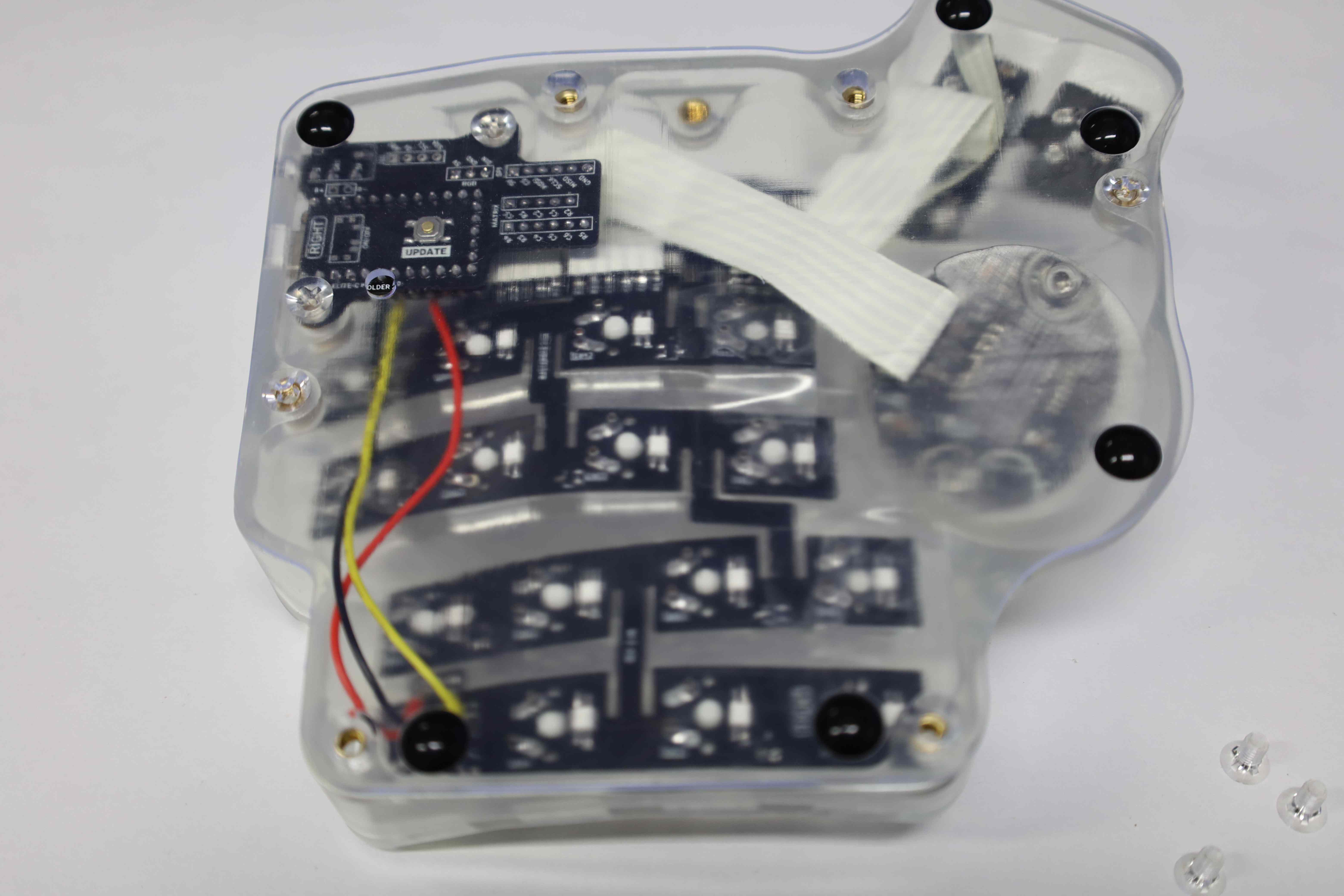
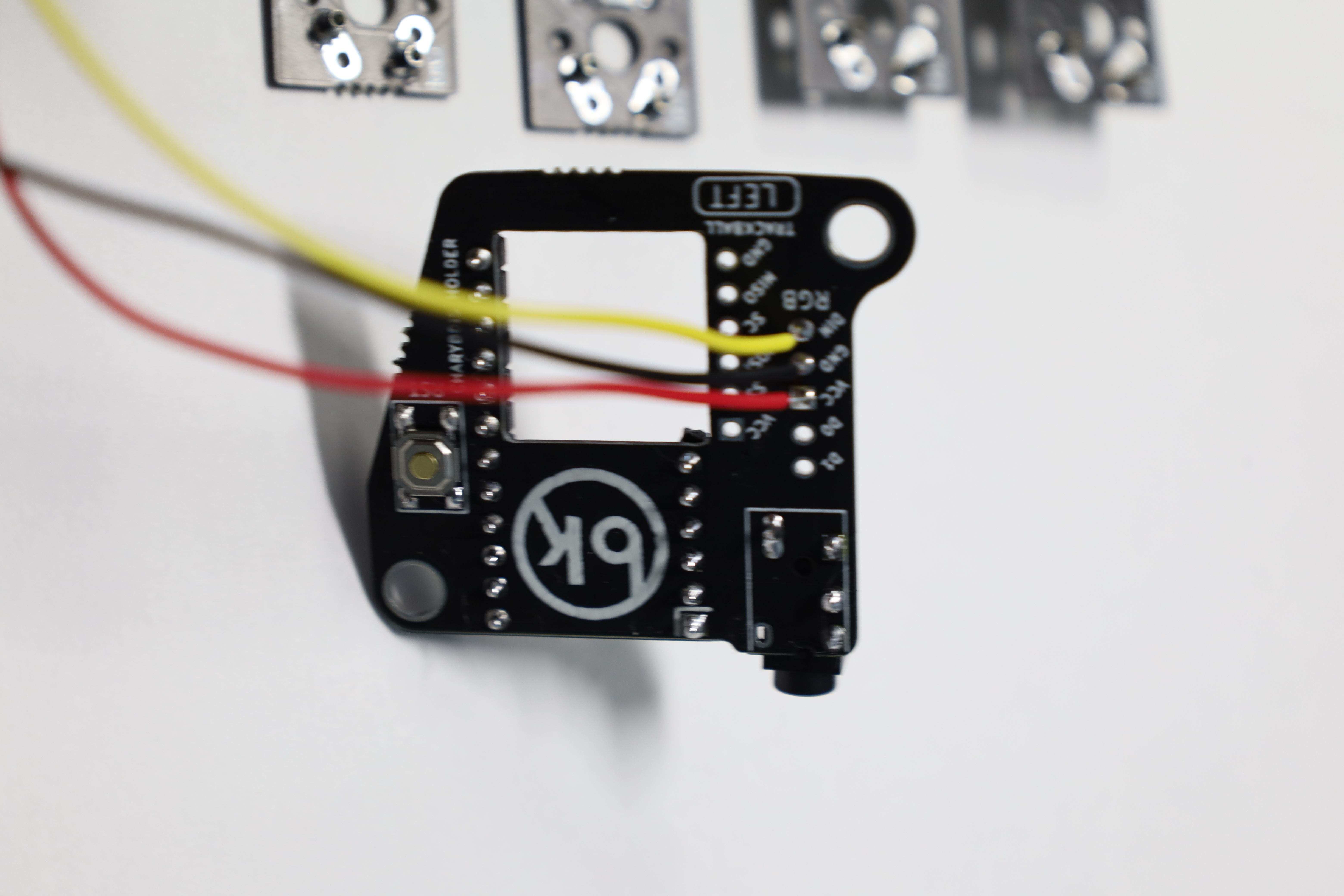
[RGB cables]
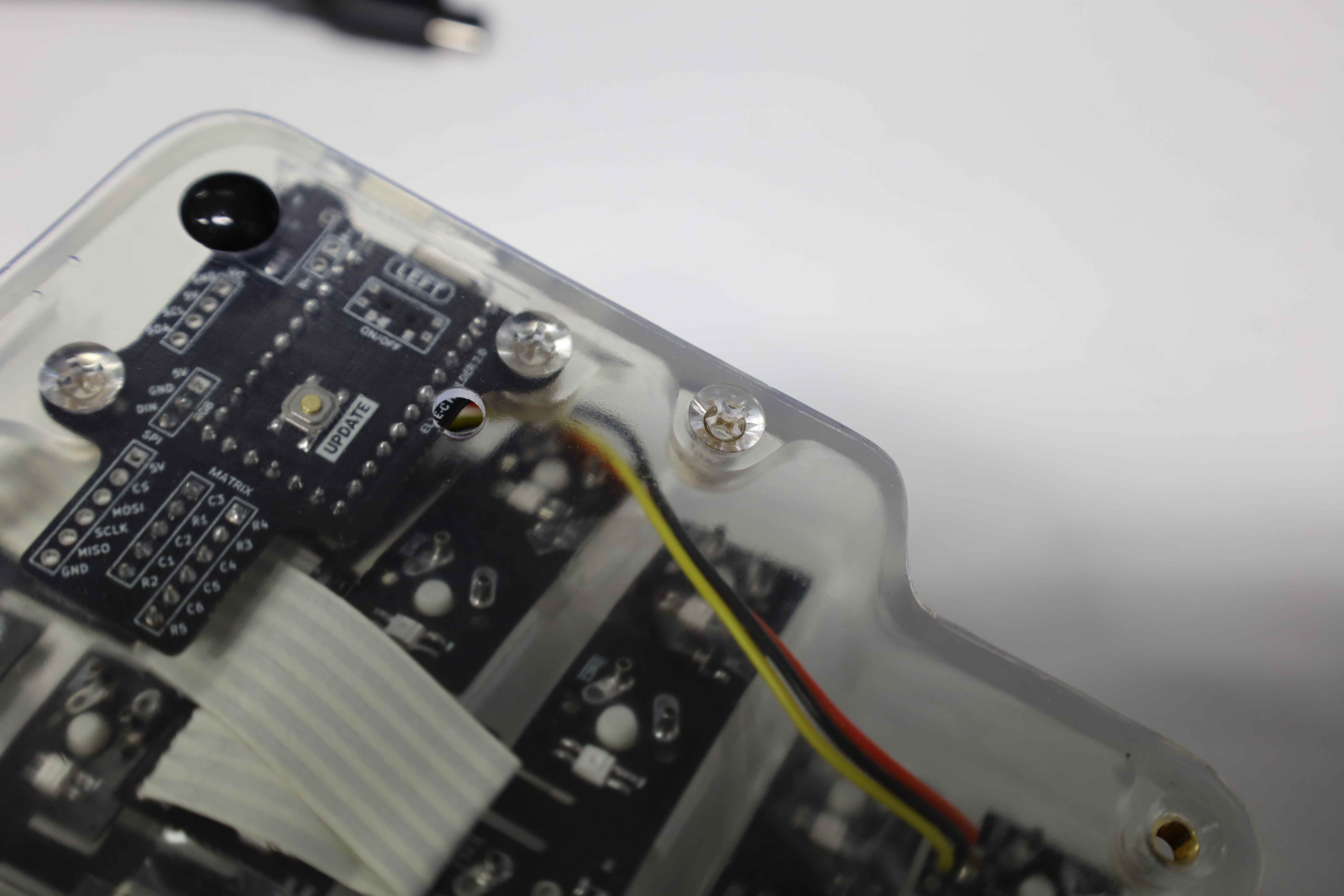
The 3 wires ribbon cable is to be installed on the backside of the board, bottom left on the picture below. For black-red-yellow triplet of cables is to be installed next to the capacitor and resistors, also on the backside of the board. As per electronics convention, match black, red, and yellow to GND, VCC or 5V, and DIN or DOUT.

3.5. Connecting the thumb cluster
DISCLAIMER Follow the official build guide for this particularly sensitive part. This post is to be used as a reference for a prospective builder, at best.
The Scylla left’s thumb cluster has to be connected with one of the 6 wire ribbon cables coming from the main PCB, and also the 3 wire ribbon cable in case of an RGB backlit key build.
As rules of thumb:
- the ribbon cables connect the main PCB side marked as (left) to the thumb cluster board side also marked as (left).
- align the R5 pin on the main PCB to the R5 pin on the thumb cluster.
For the RGB 3 wires ribbon cable, the wiring is pretty straightforward: from the main PCB to the thumb cluster: GND to GND, VCC to VCC, and the last one would be either DIN -> DIN or DOUT on the thumb cluster.
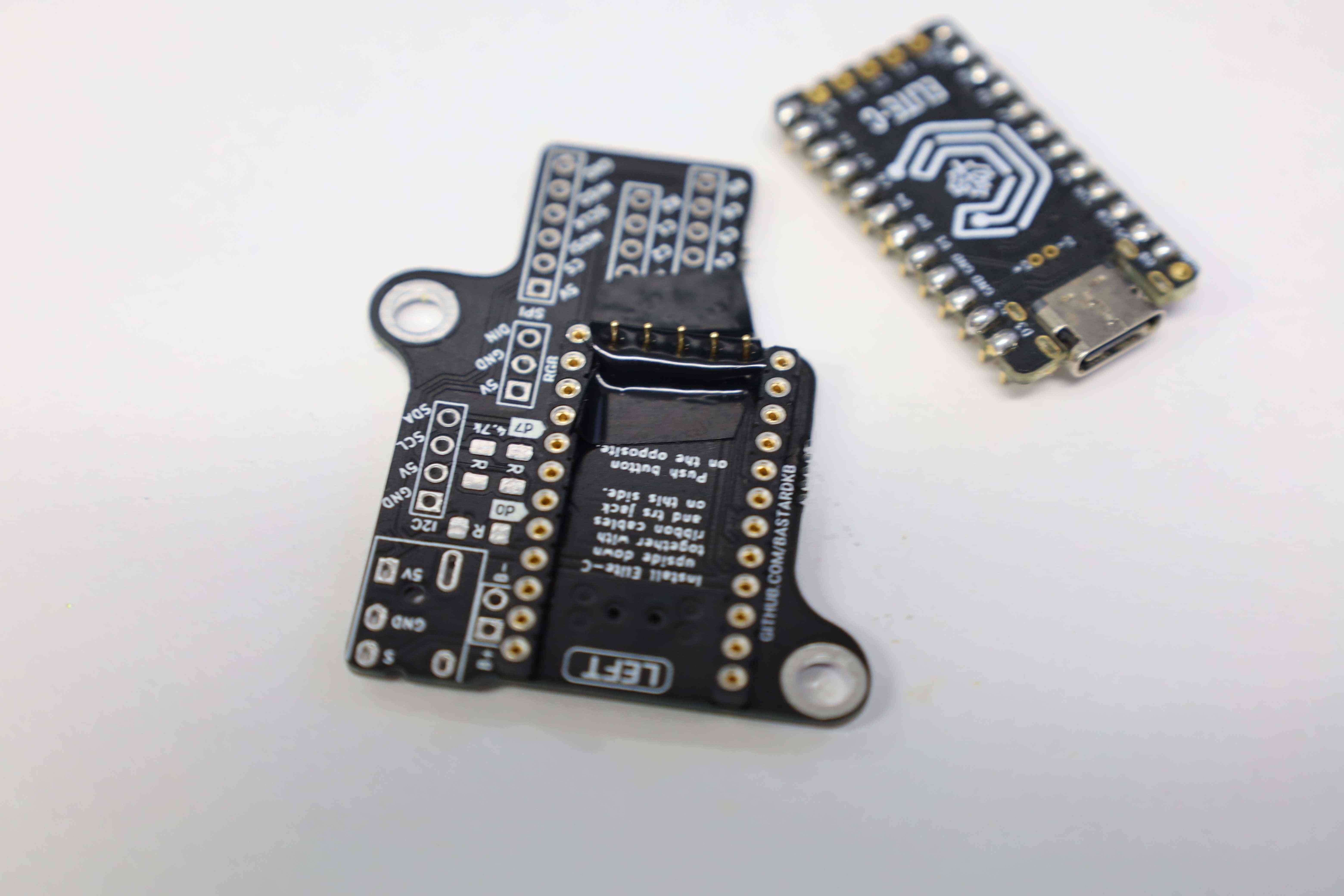
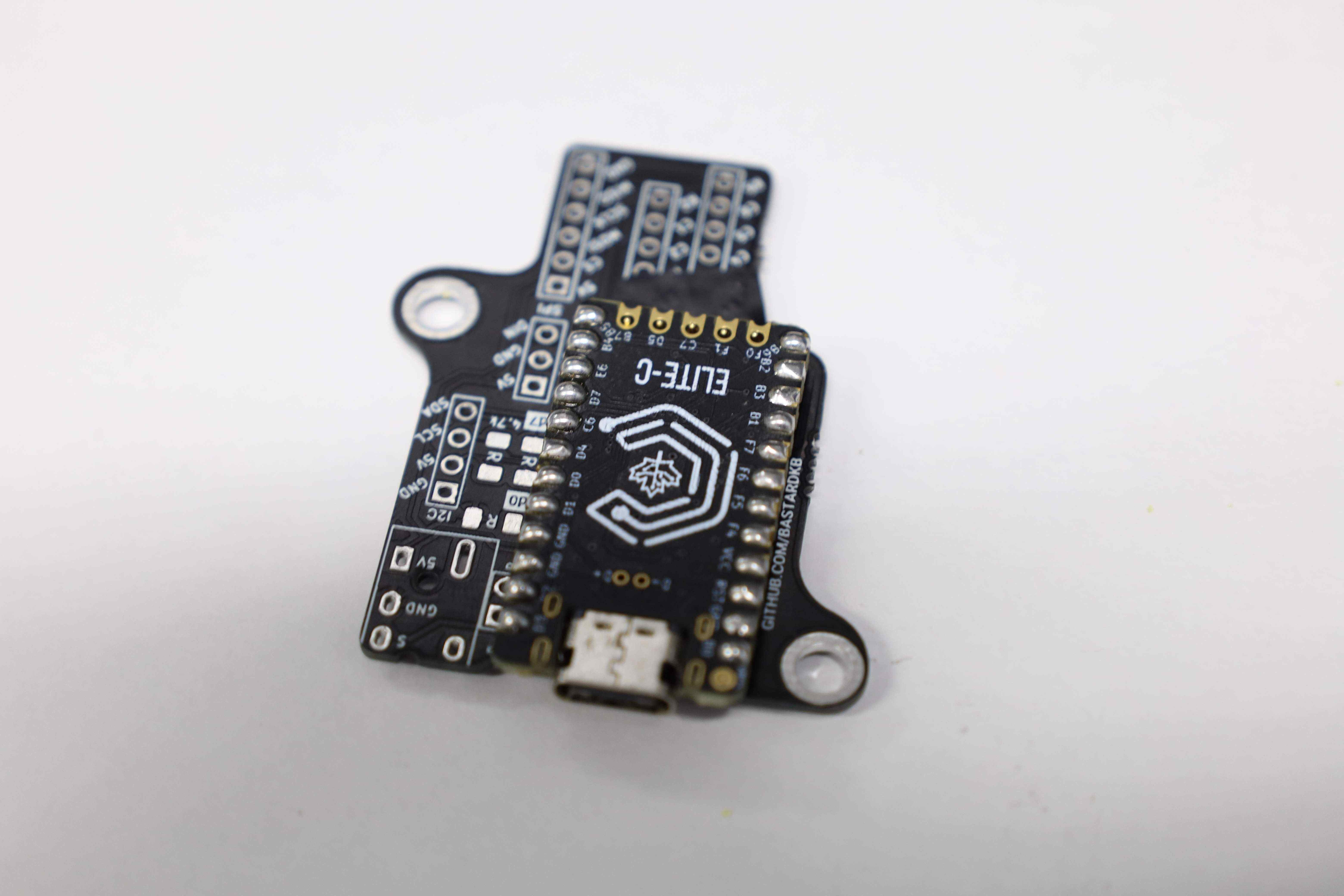
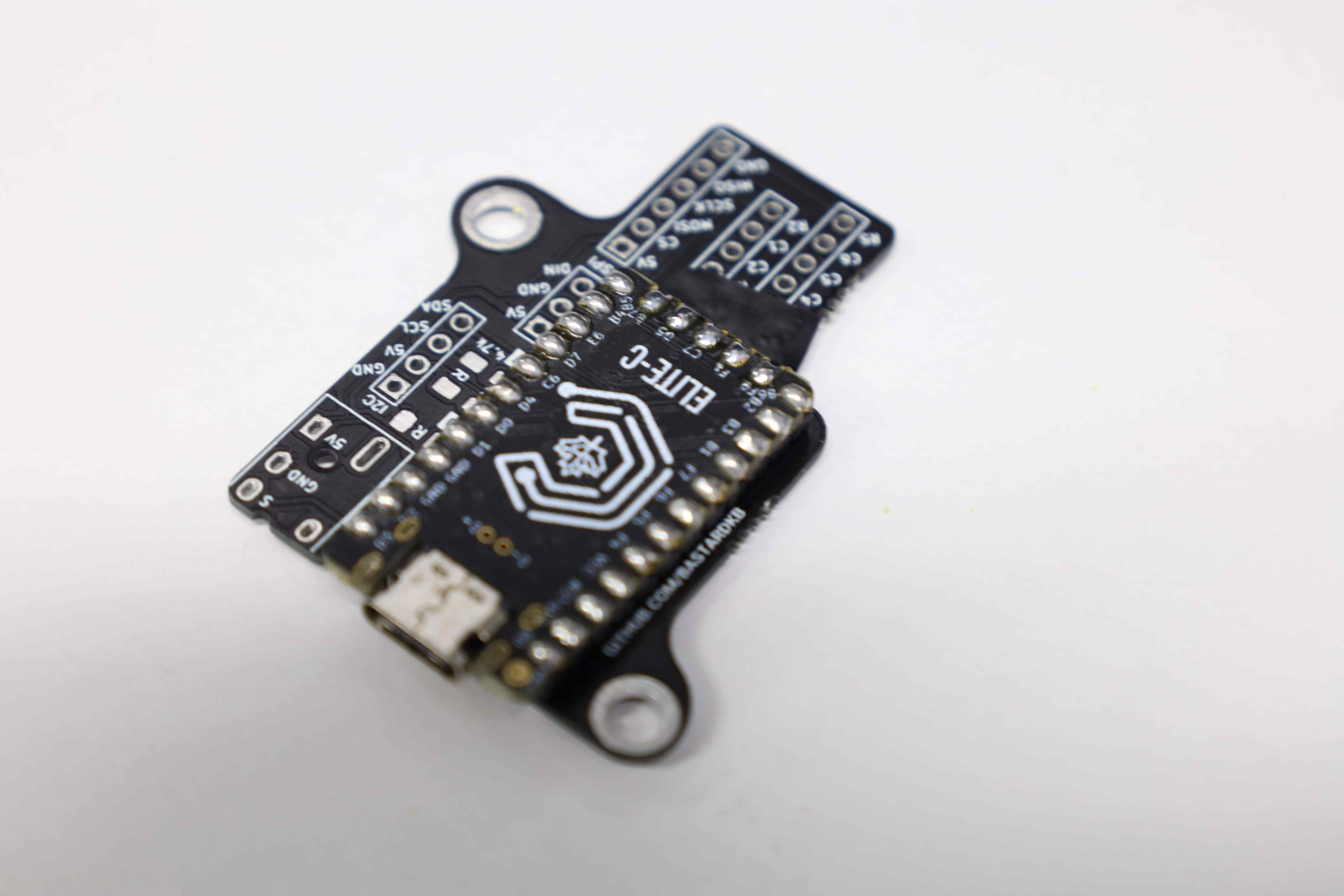
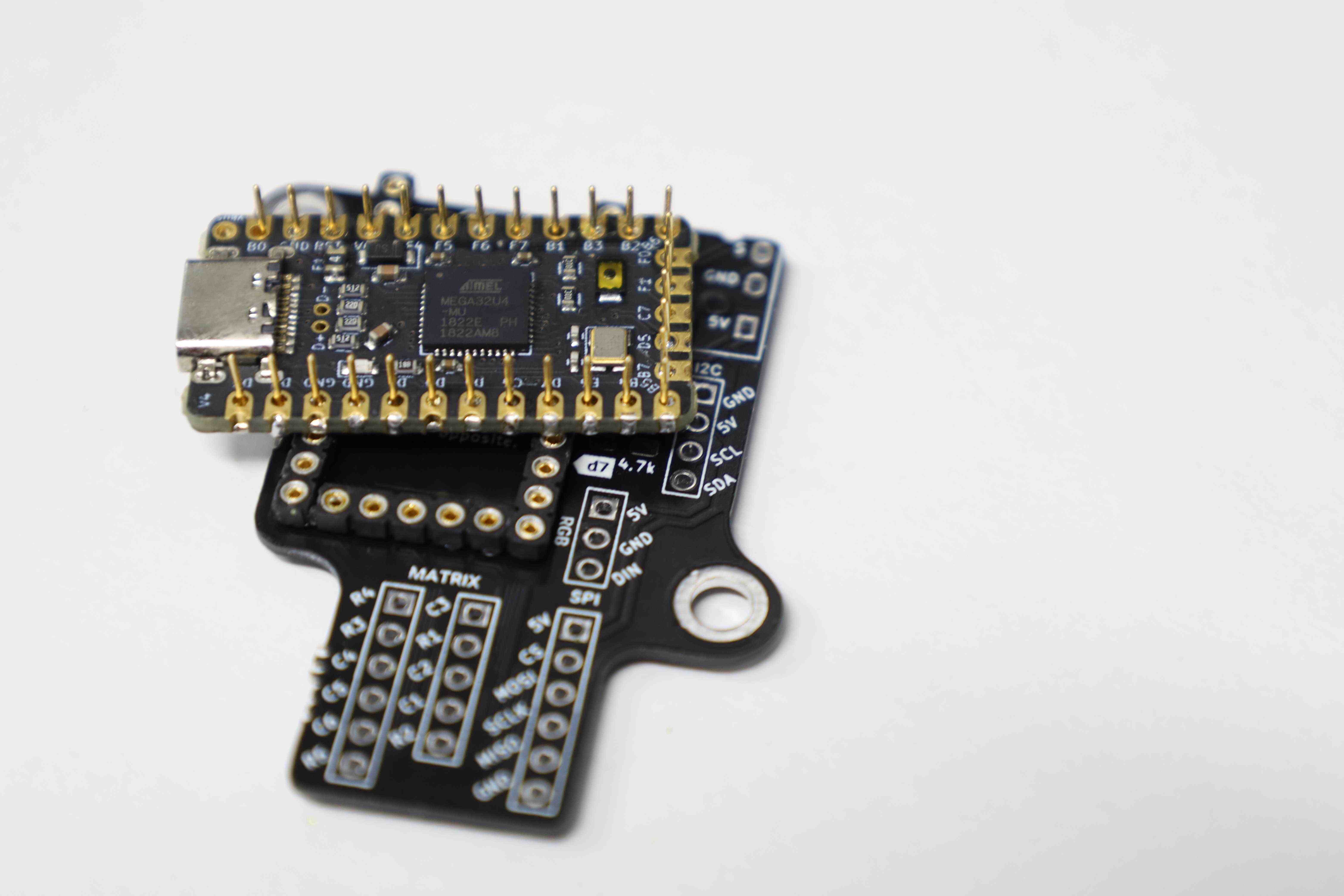
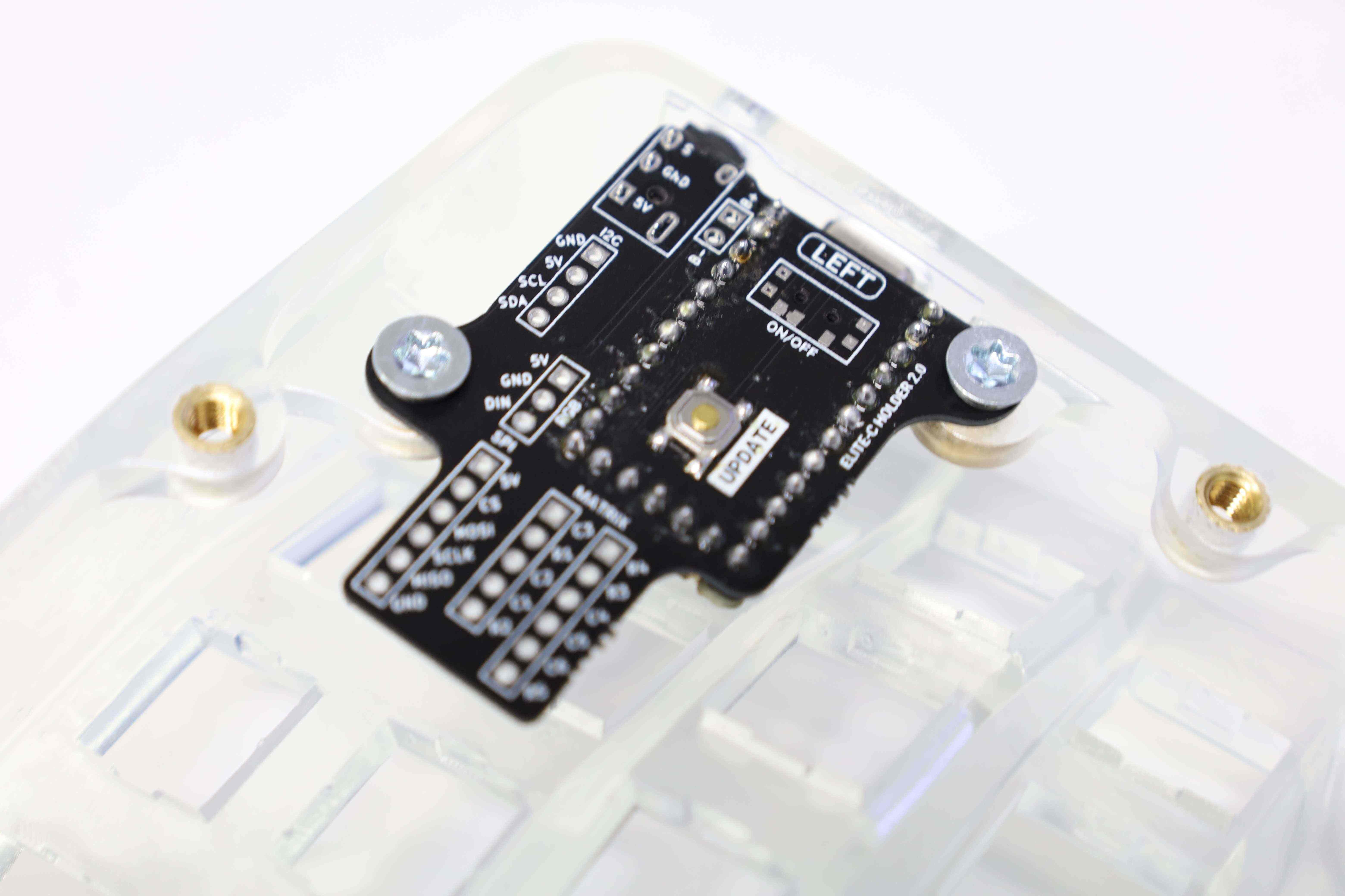
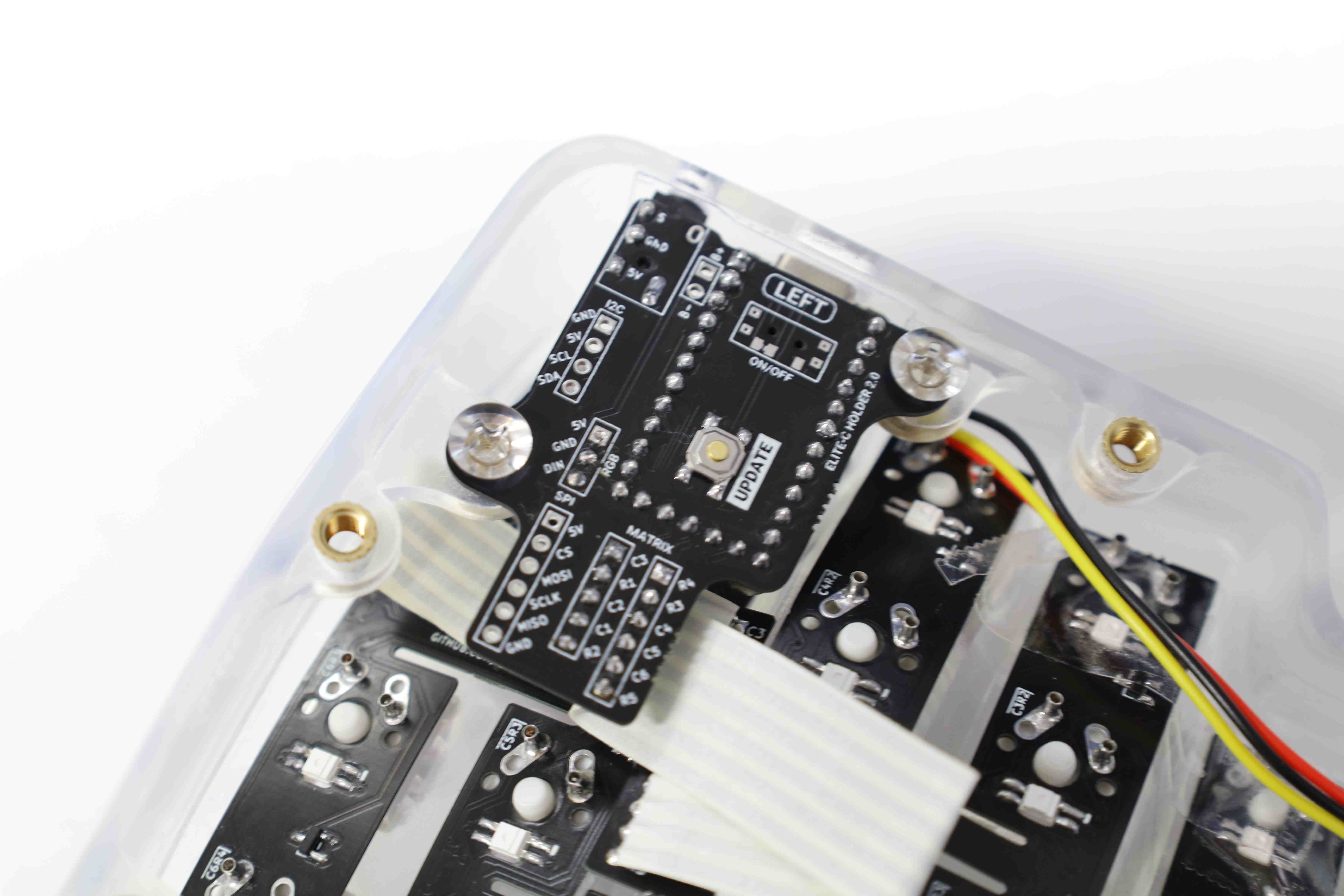
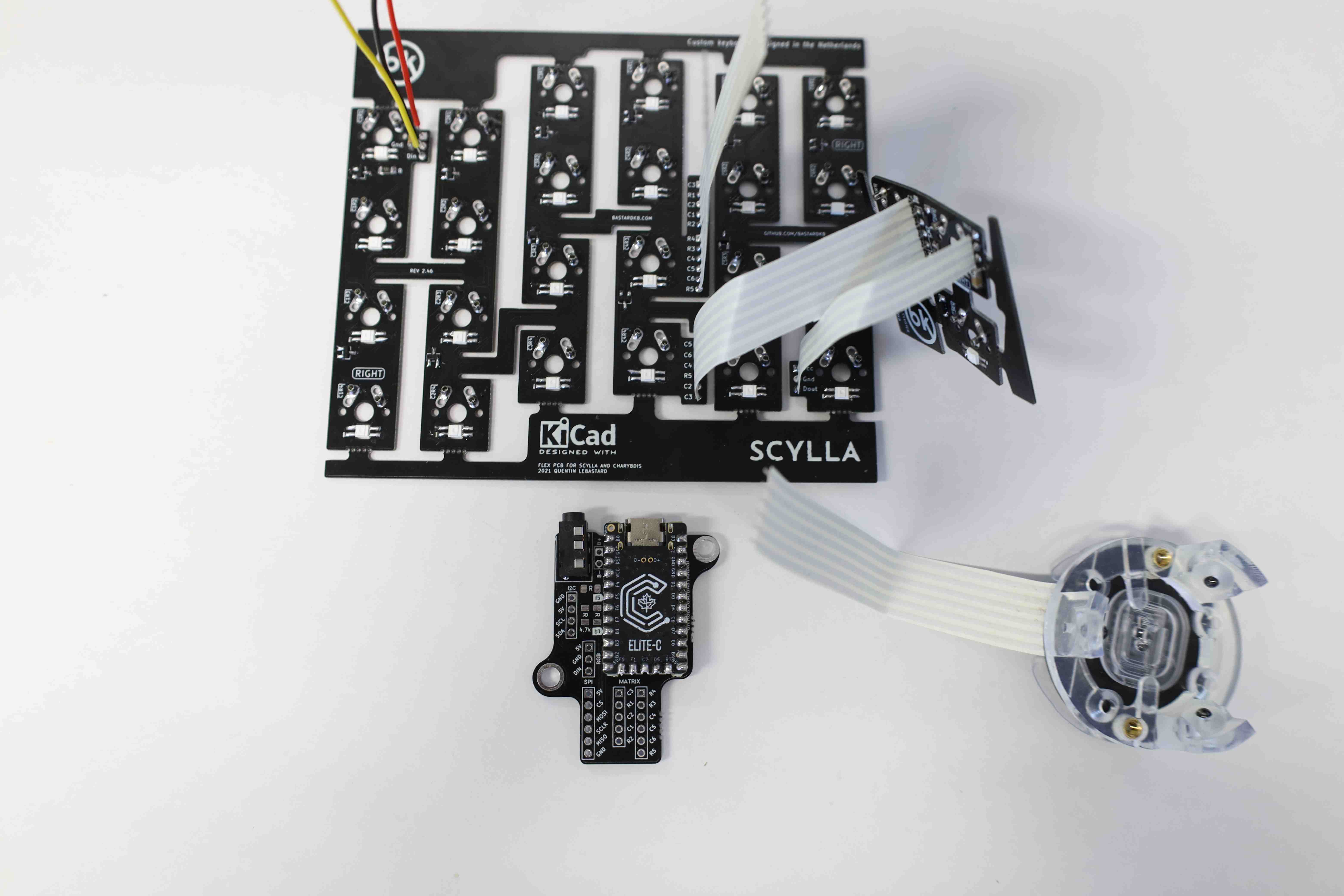
3.6. Installing the Elite-C MCU
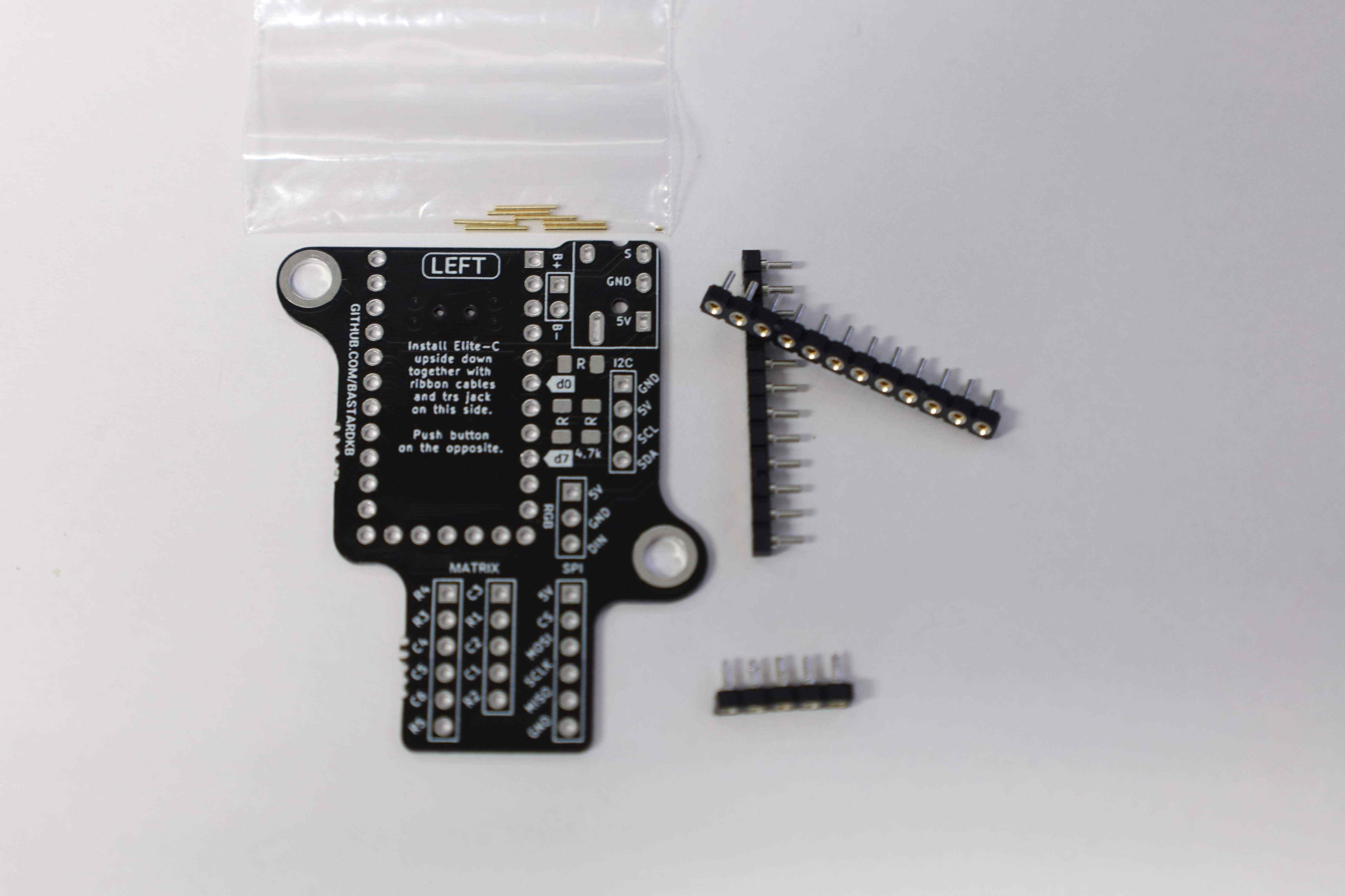
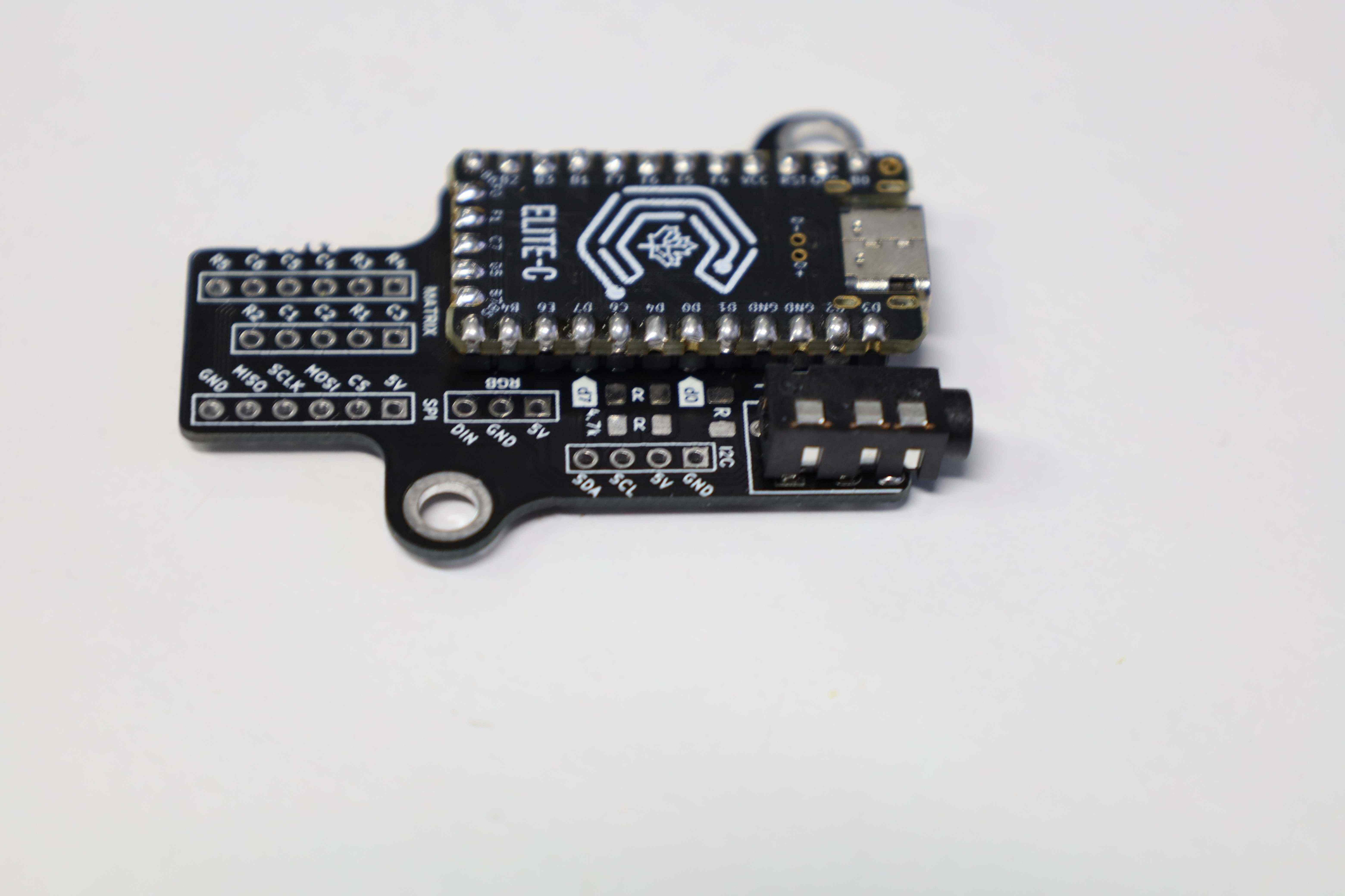
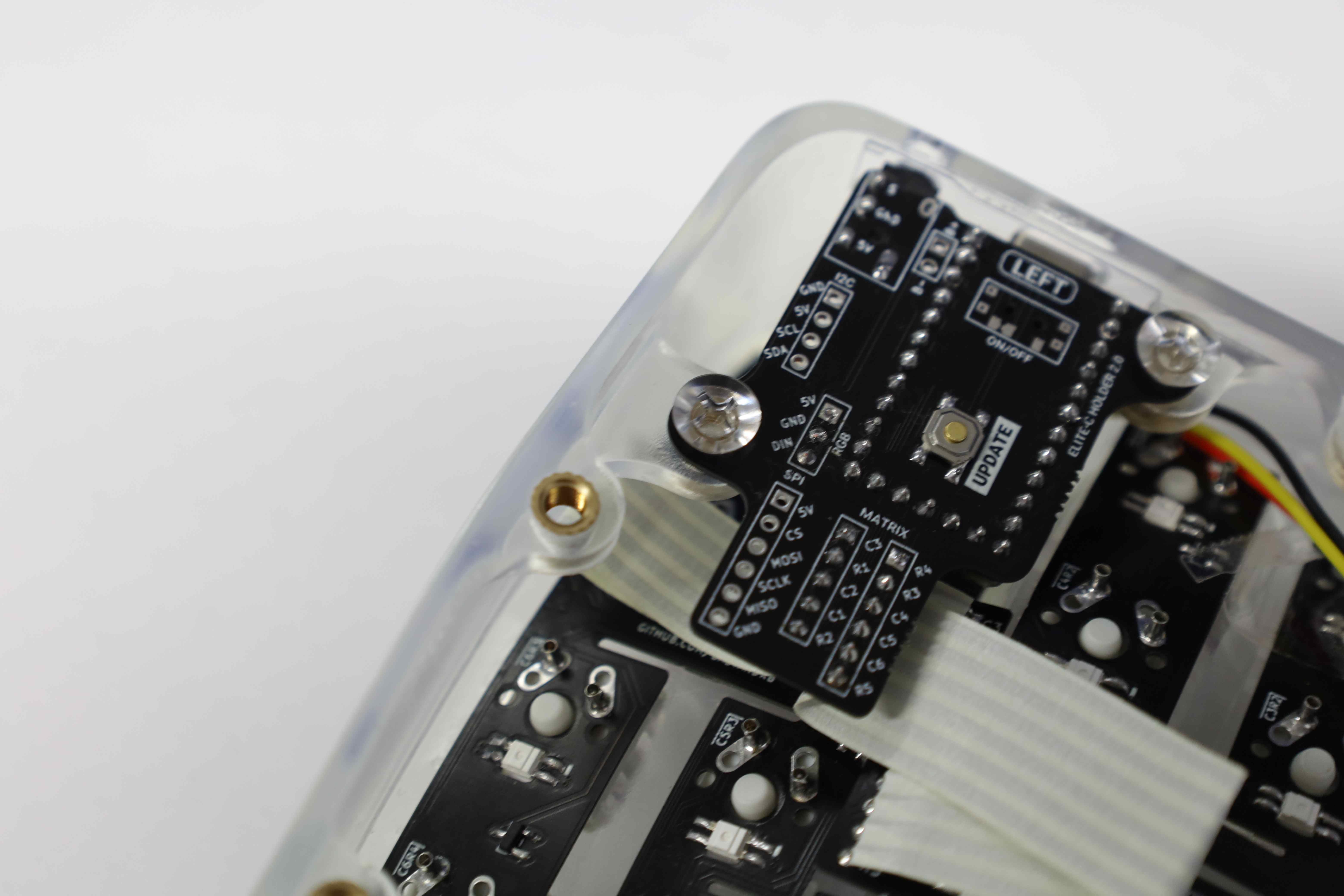
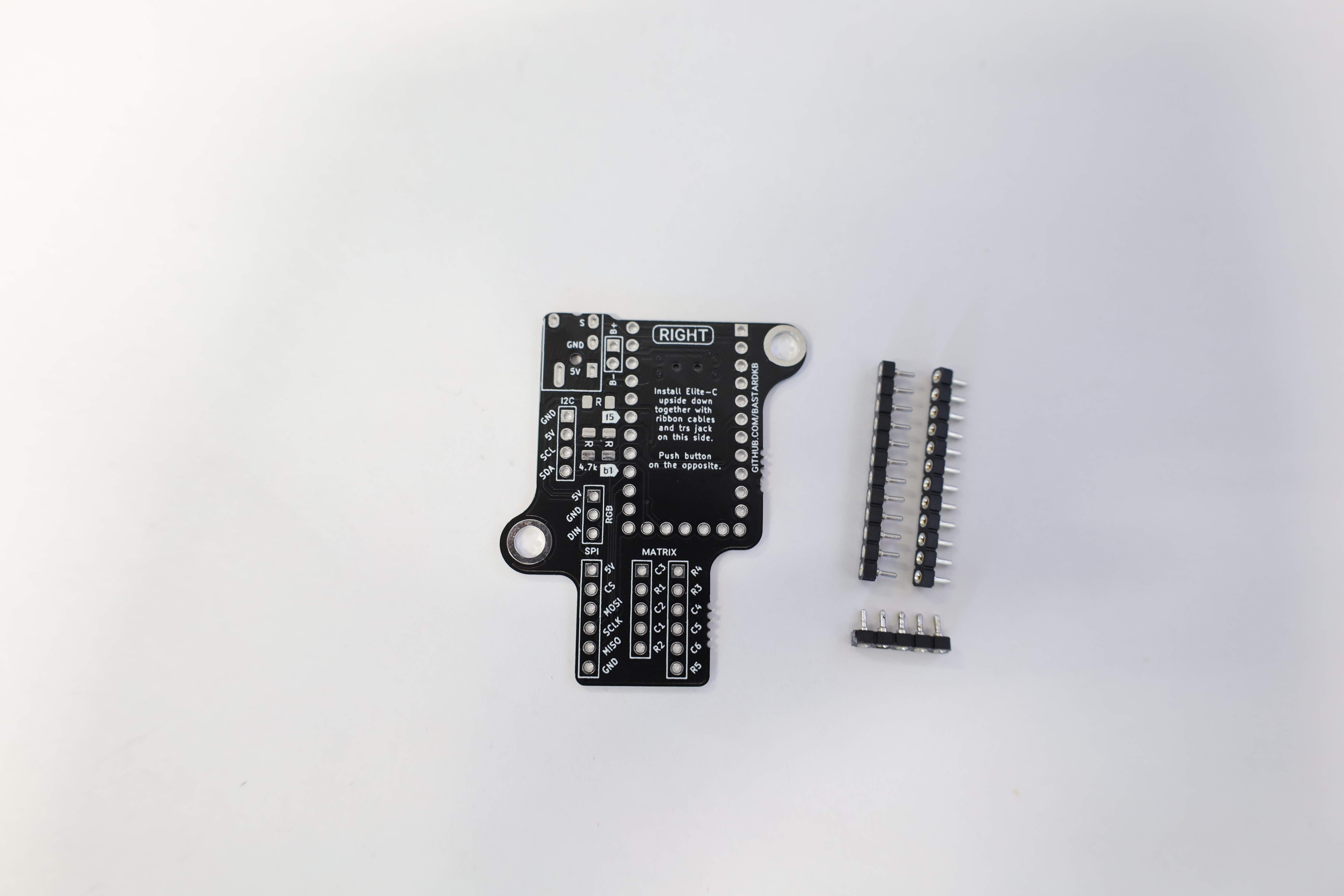
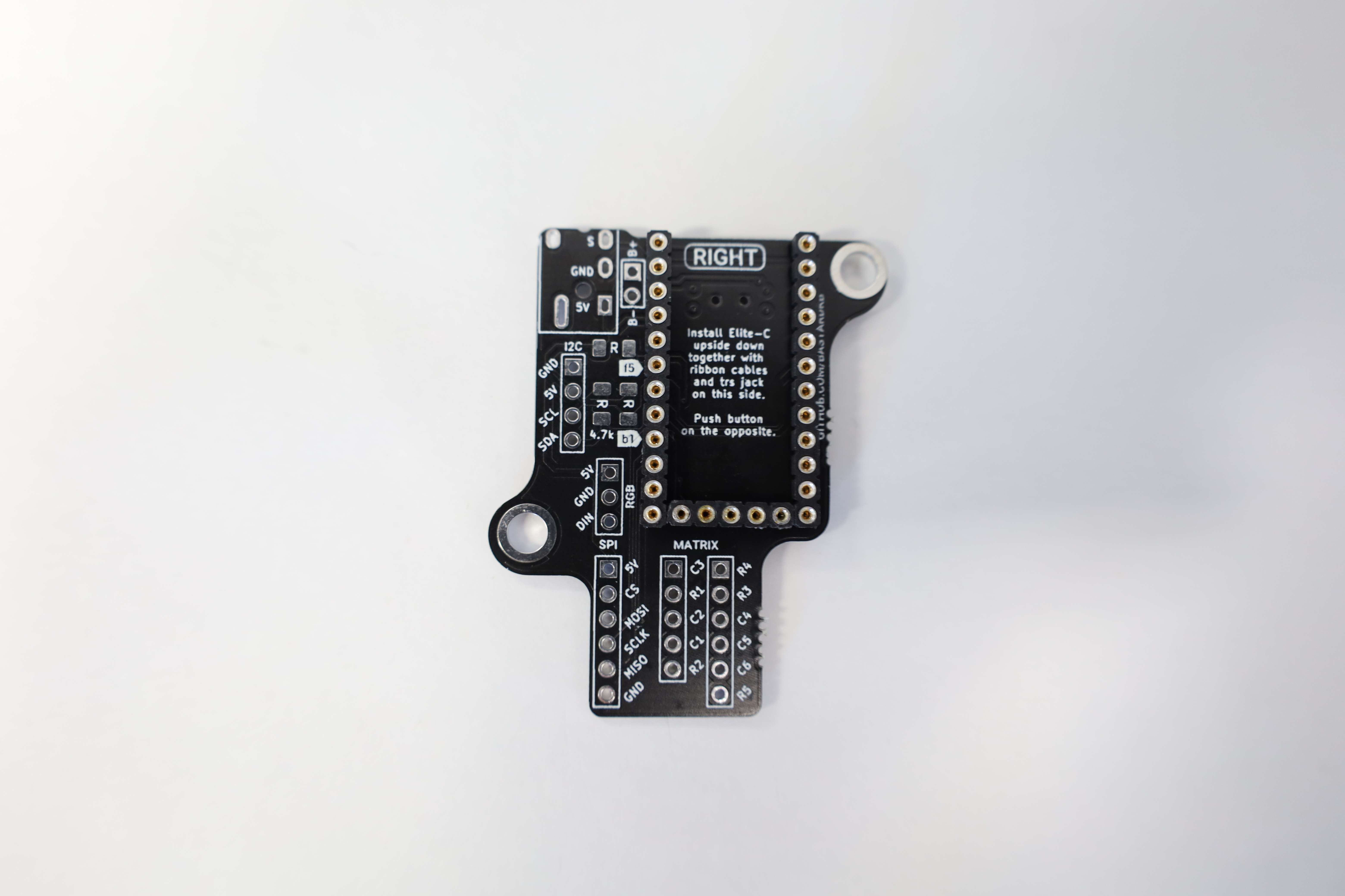
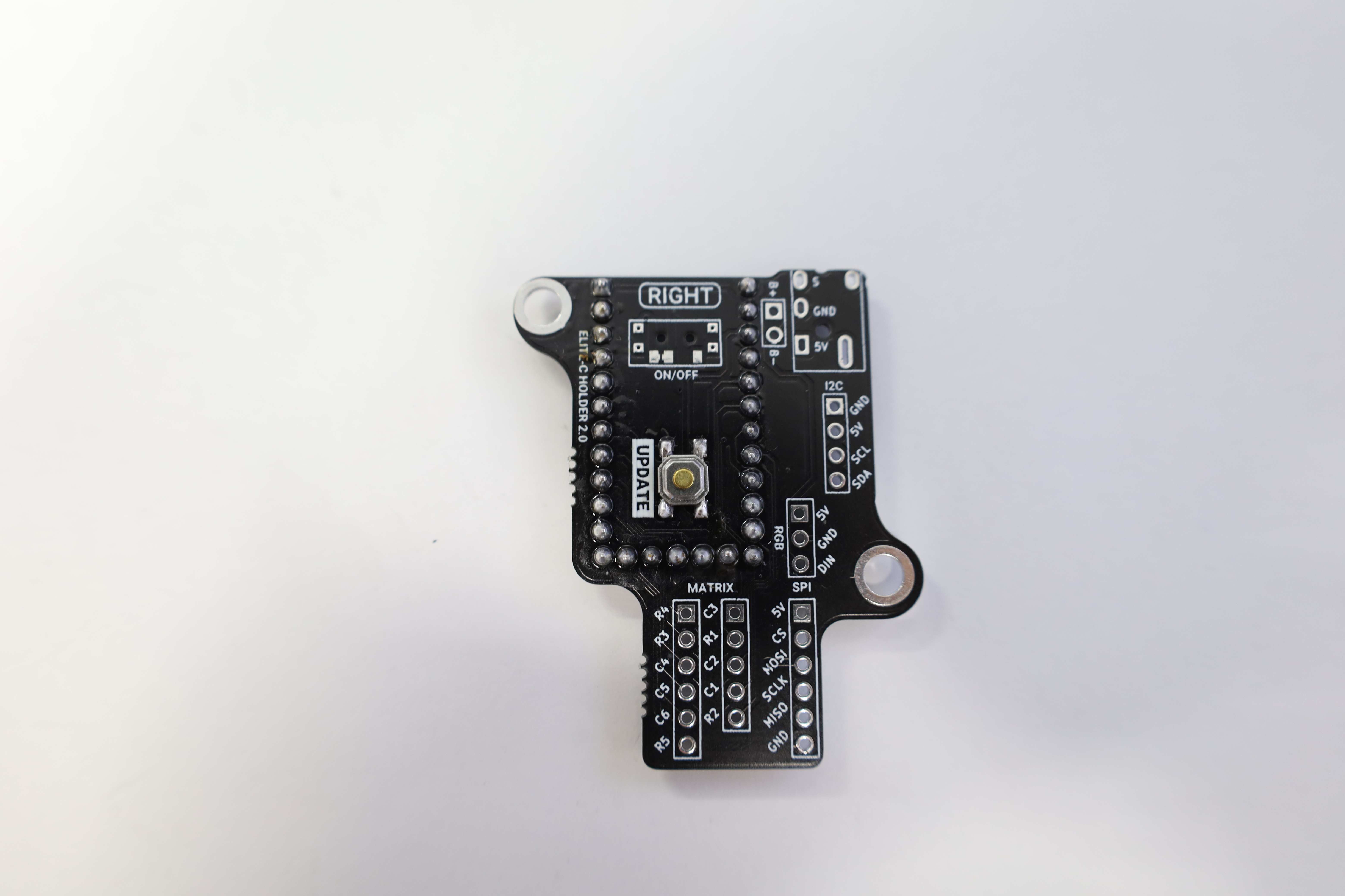
With the board’s related components installed, and the boards themselves partially assembled, the next step is to prepare the MCU shield and finalize the electronics of the keyboard.
This build (showcase 1) uses an Elite C as MCU, with the Shield v2. Meanwhile, the earlier build (showcase 2) actually uses a Shield v1. The Shield v2 enables easier and cleaner installation. Namely, unlike the v1, the shield has holes for all the pins that come from the MCU, and the ribbon cables do not have to be soldered directly onto the Elite C.
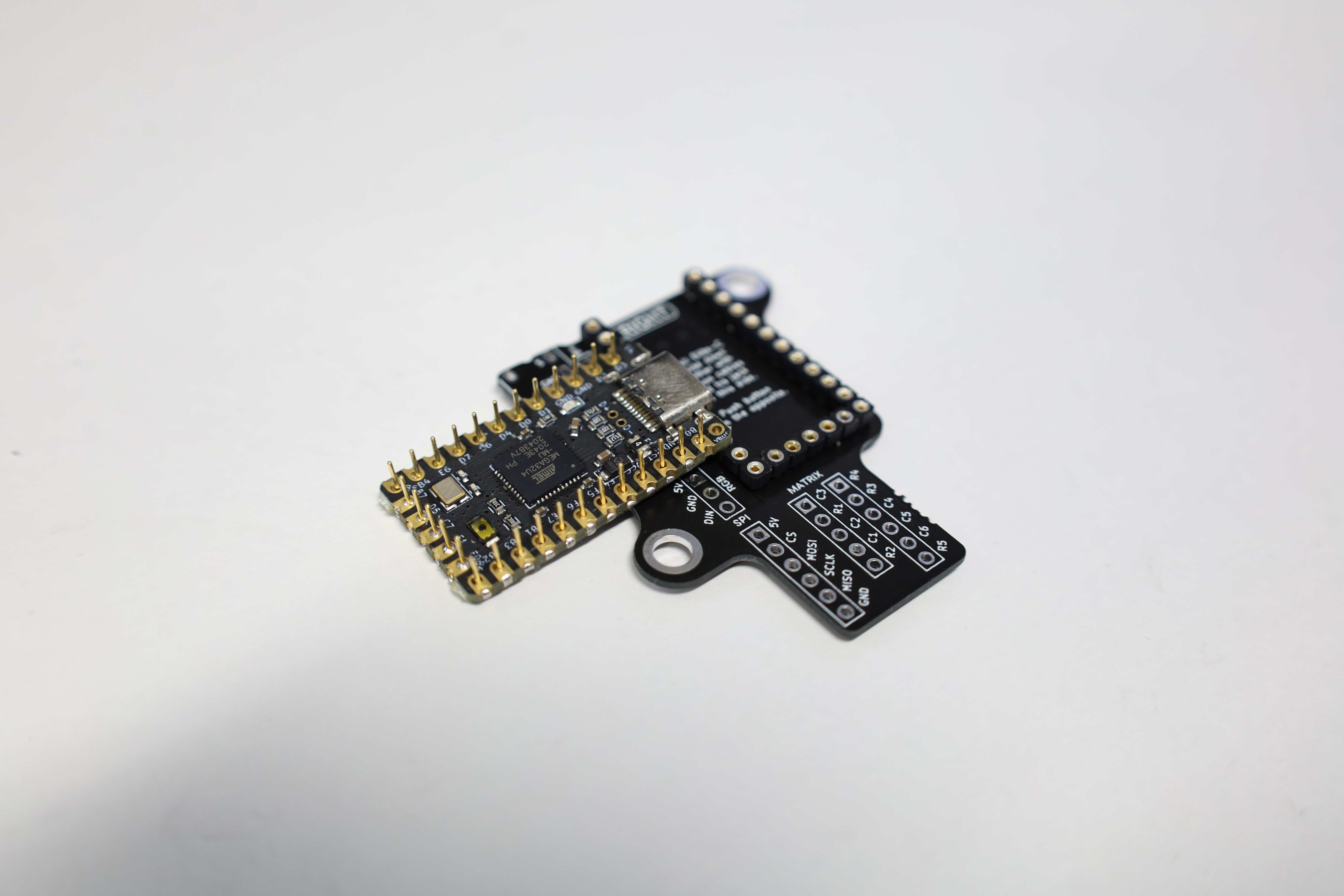
In this build, the MCU is socketed instead of directly soldered to the shield. This would allow easier repair, when the USB C port breaks for example, or when re-using the MCU in another keyboard build.
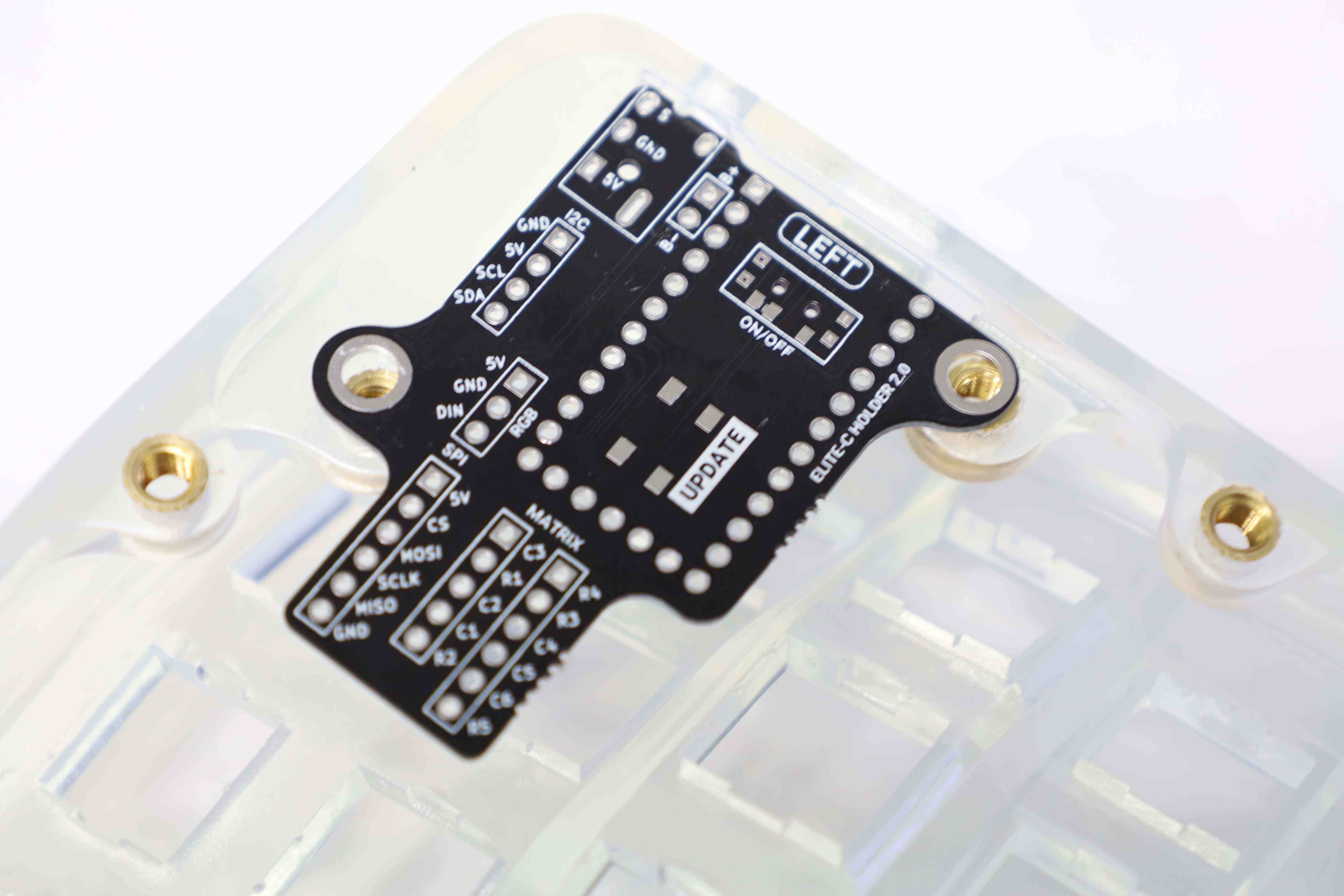
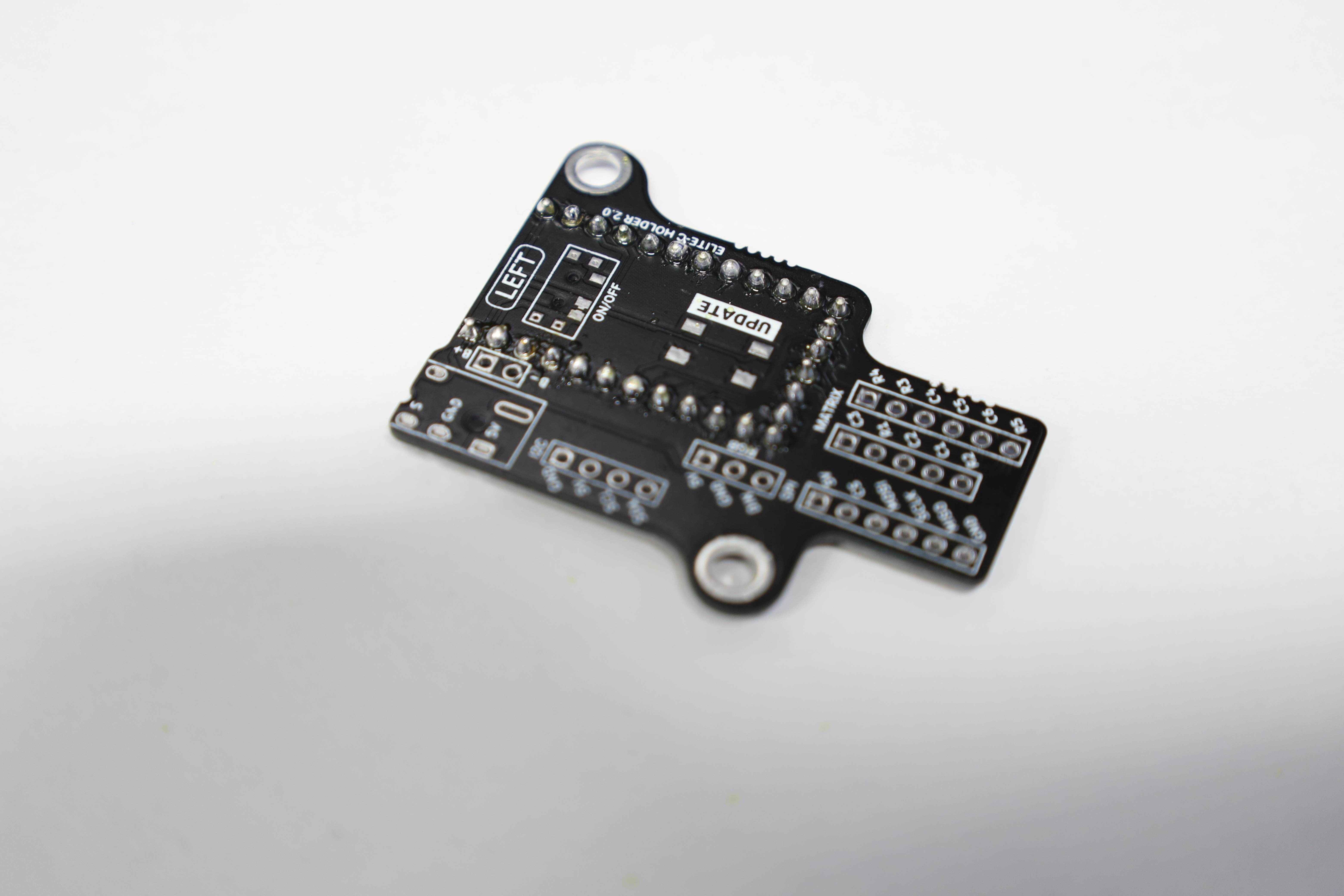
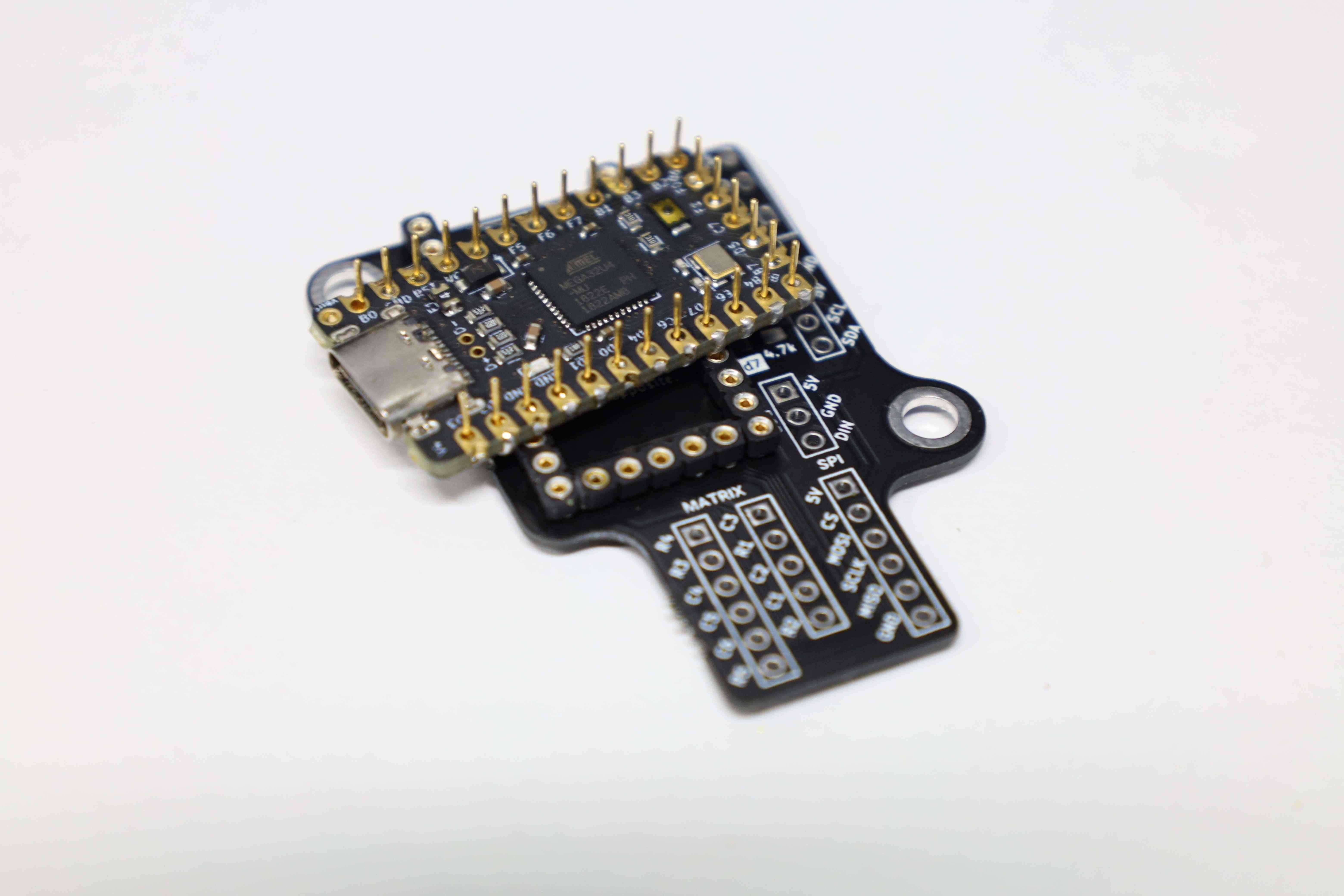
Installing the header sockets for the MCU is straightforward: insert, flip, and solder.
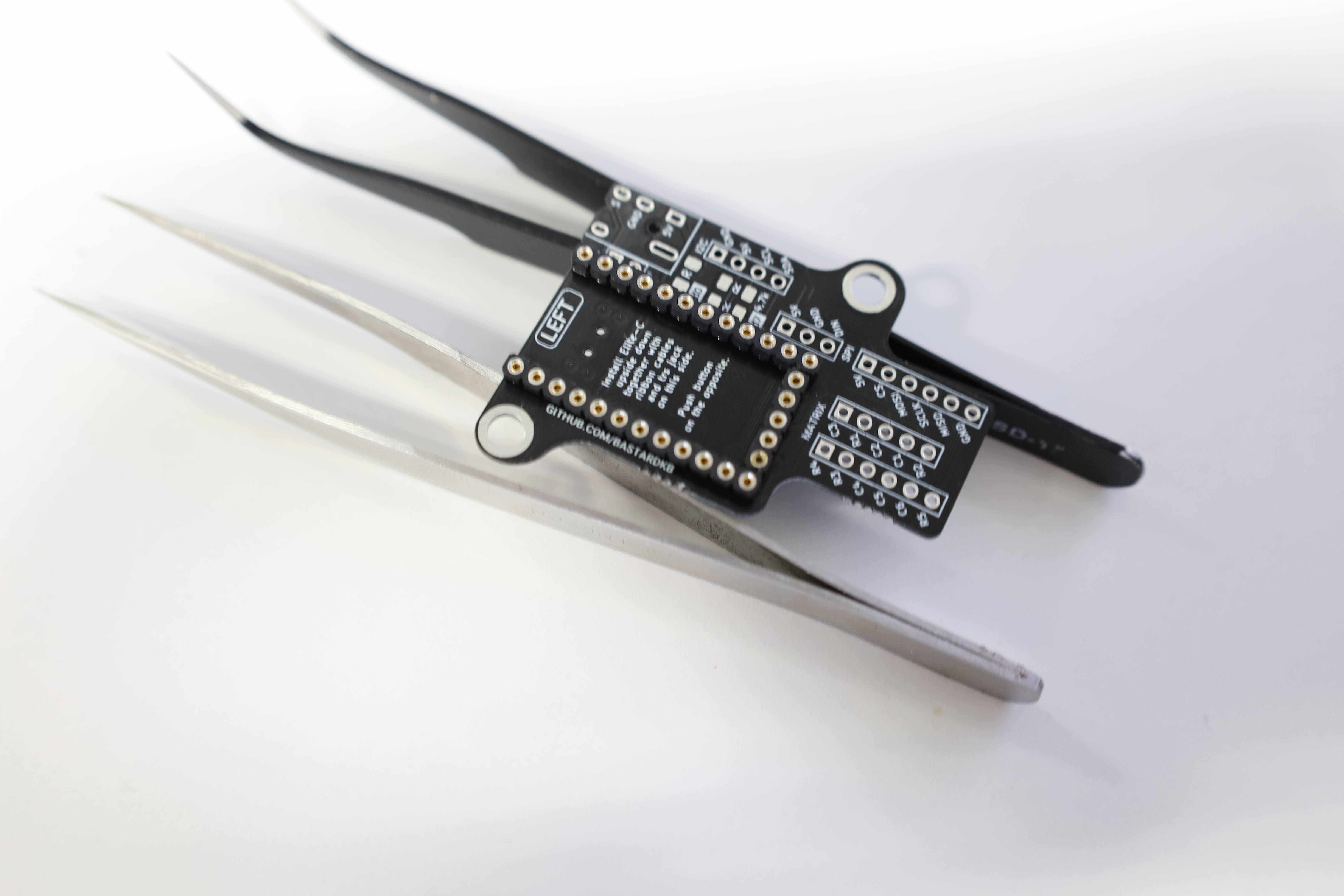


The Elite C used for this build is actually from the previous ErgoDash keyboard, where the pins were already installed into the lateral sides of the Elite C. Henceforth, only the bottom five pins have to be installed to complete this part.
When socketing for the first time, this guide from Splitkb was quite helpful.
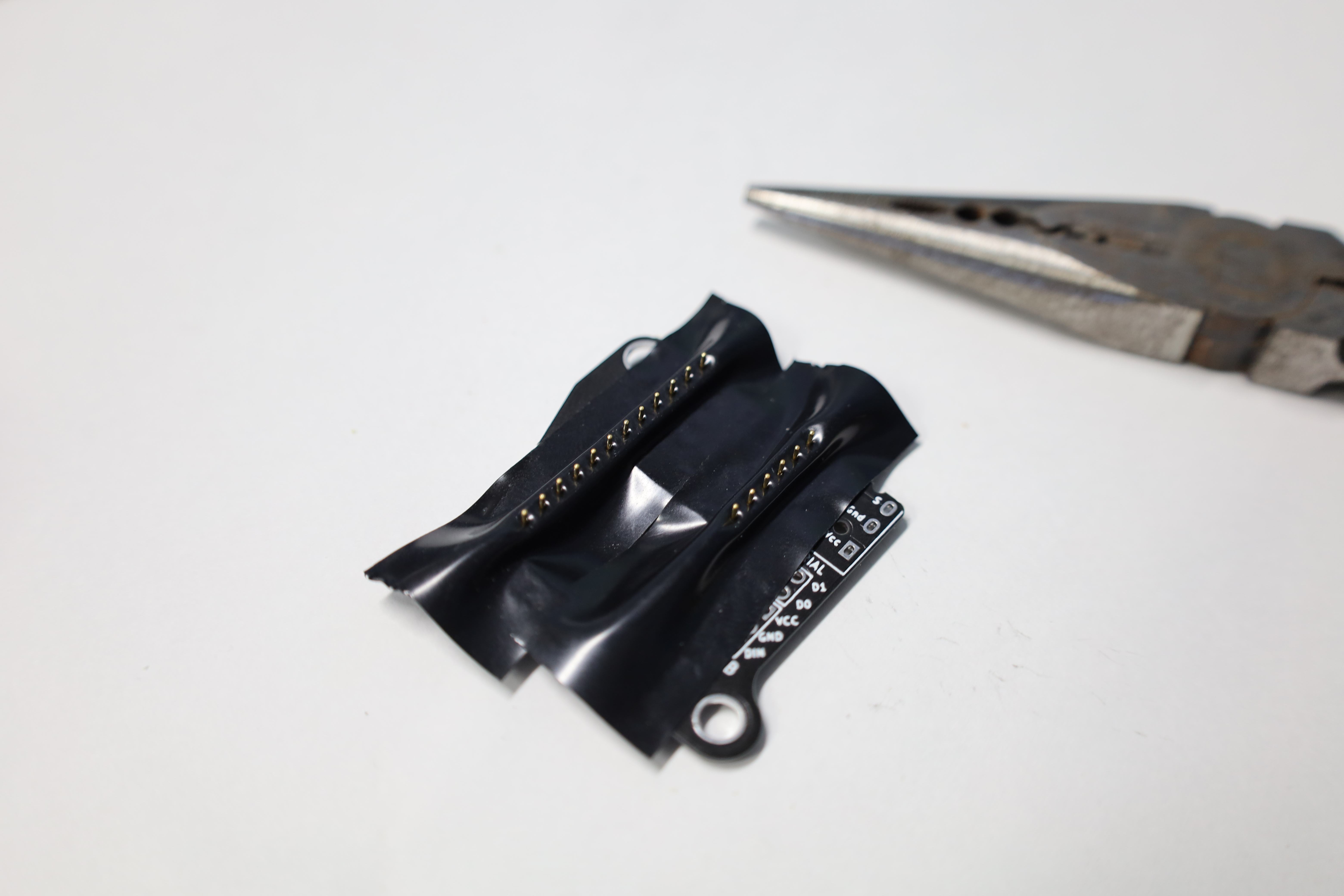
Before socketing anything, makes sure to add some tape between the header socket holes and the MCU. Otherwise, even when soldering the pins on the other side of the MCU, some tin will likely find its way in between the hole and the side of the pin that sits inside, completely defeating the purpose of socketing in the first place. A lesson that cost an ELite C was learned…
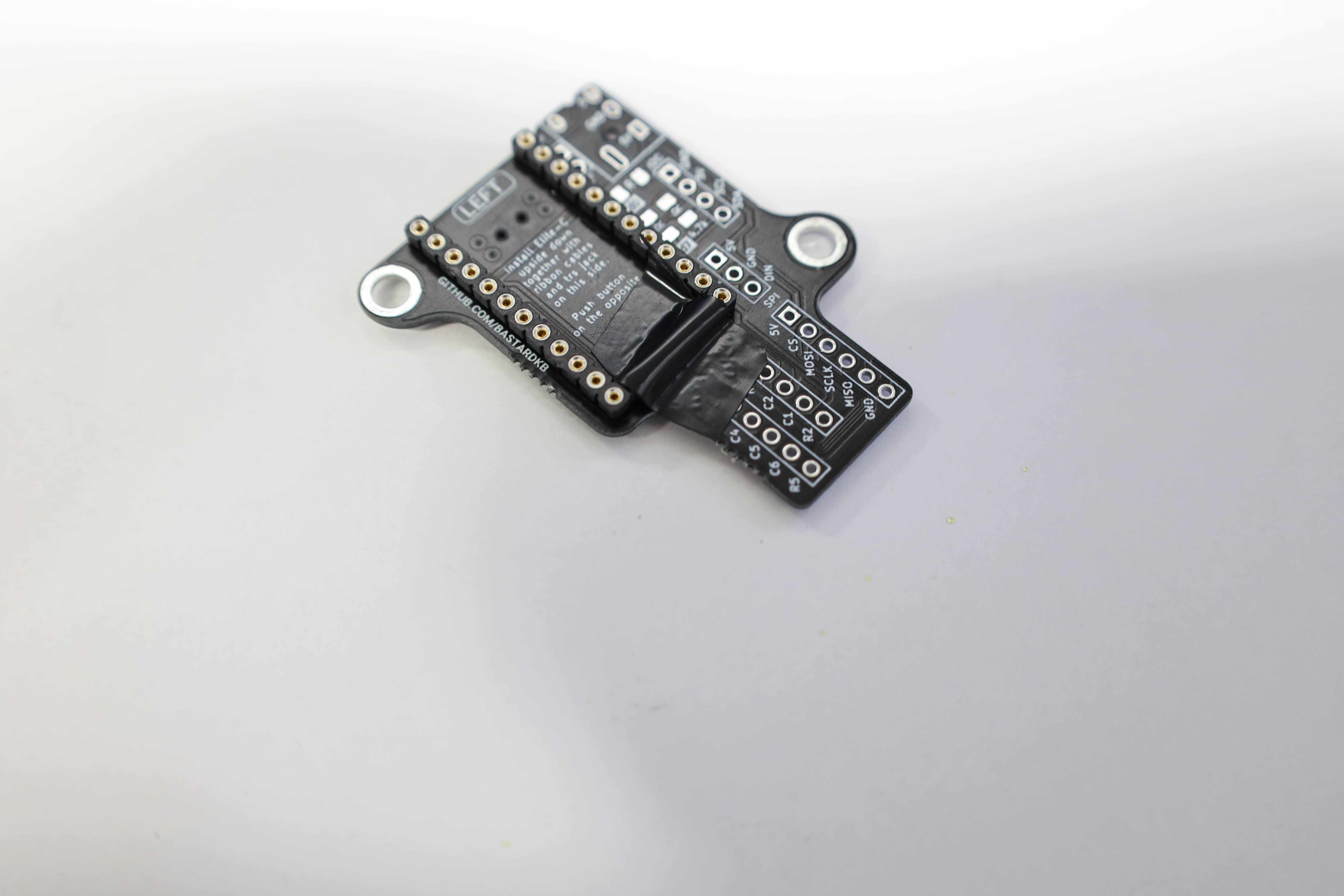
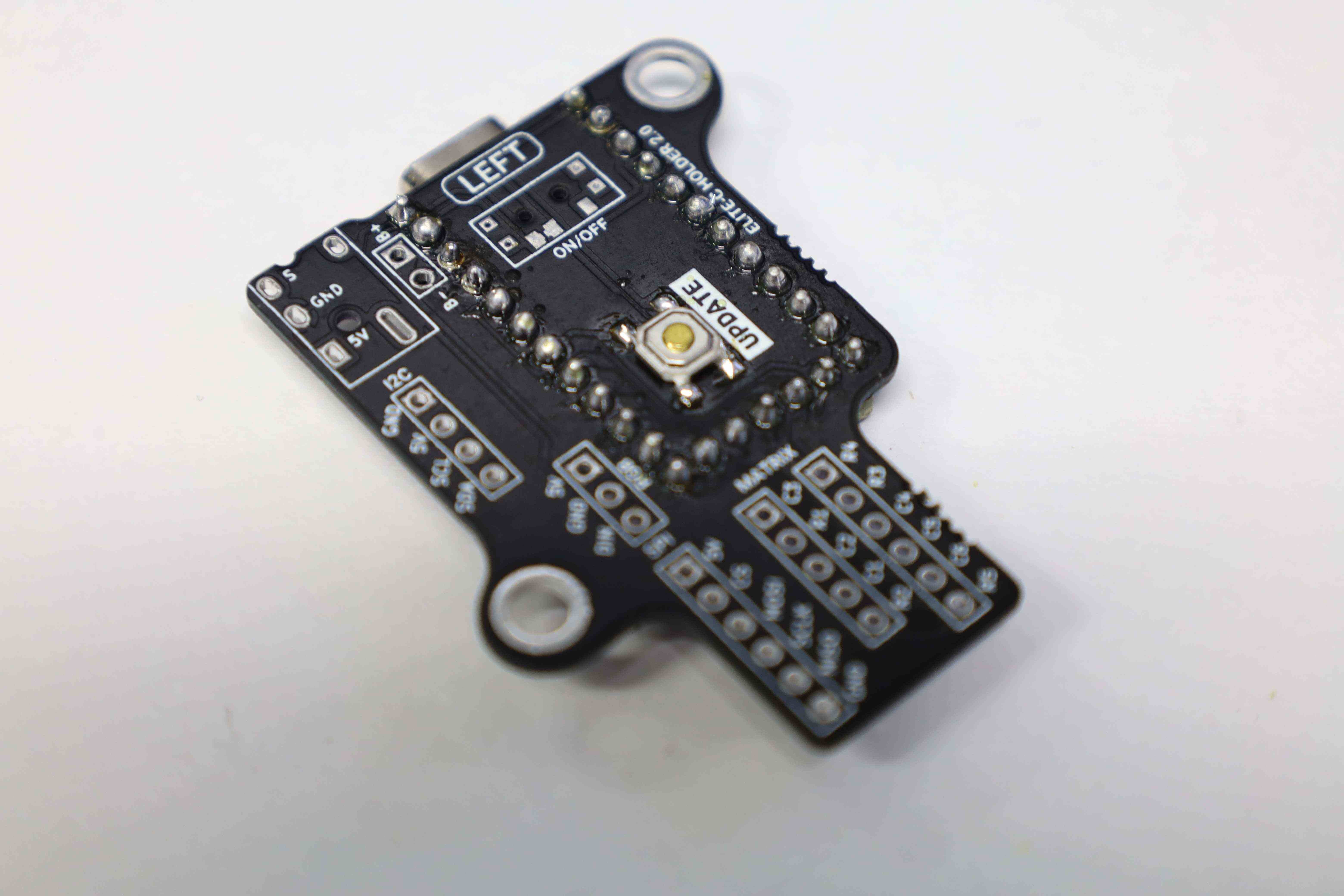
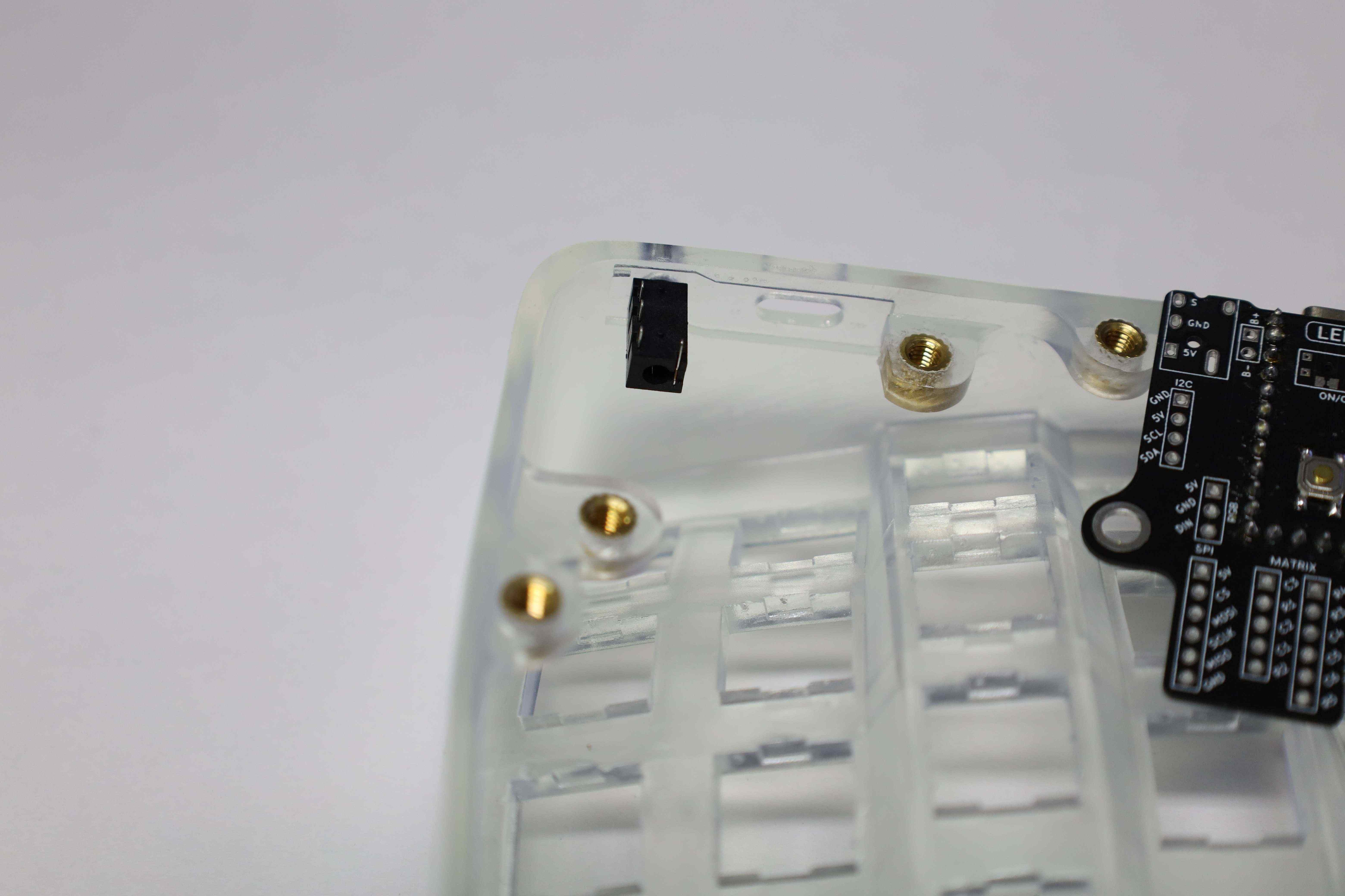
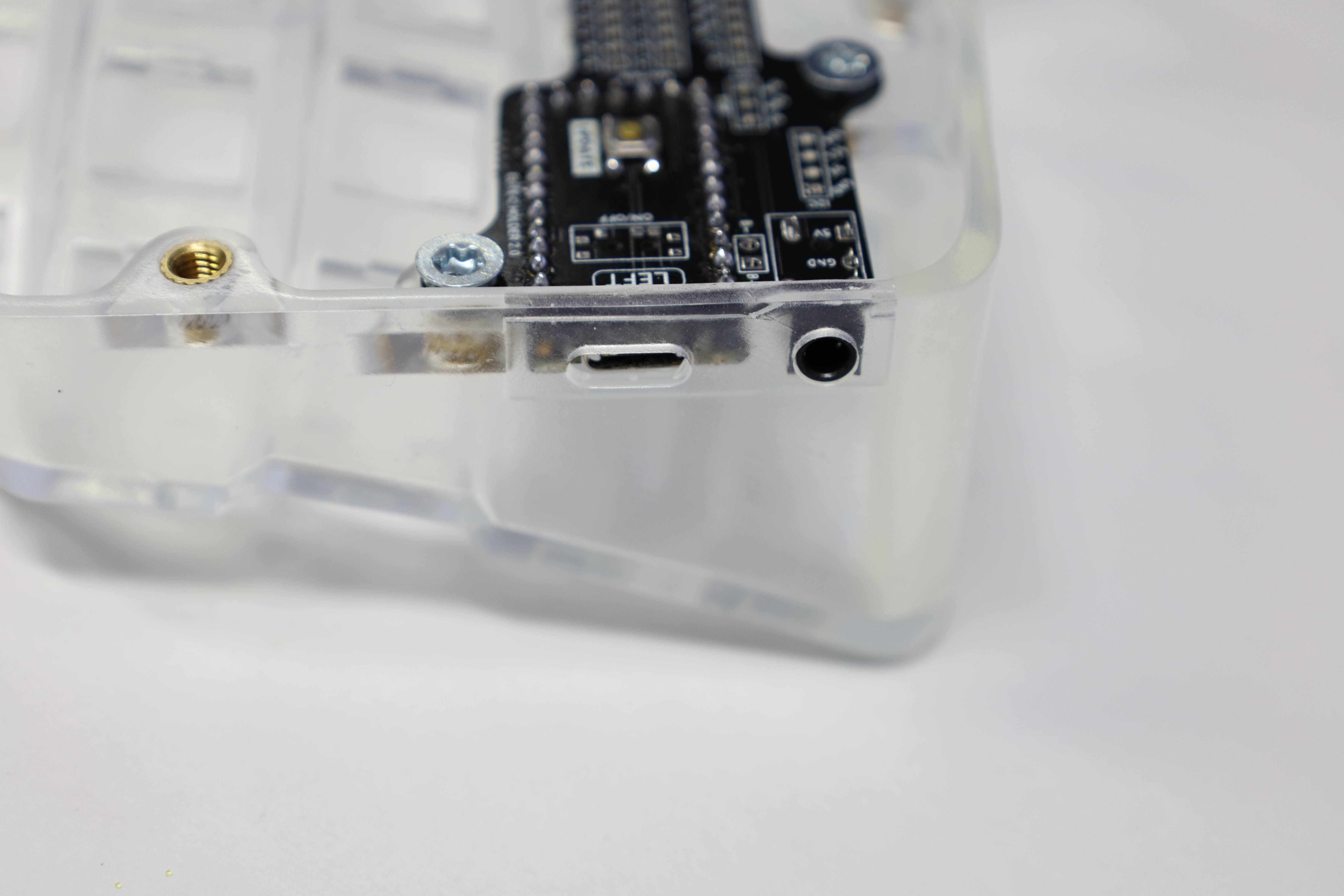
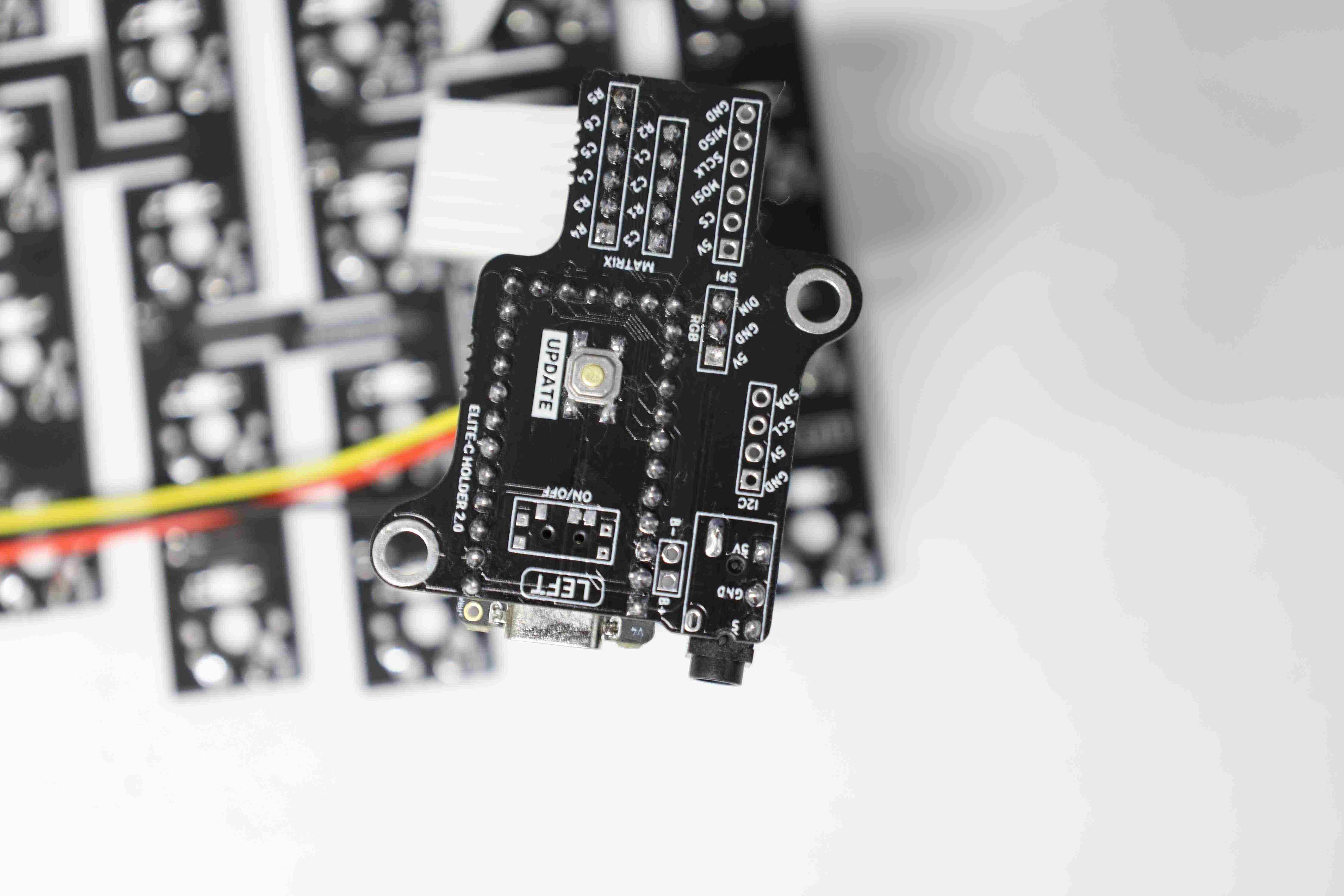
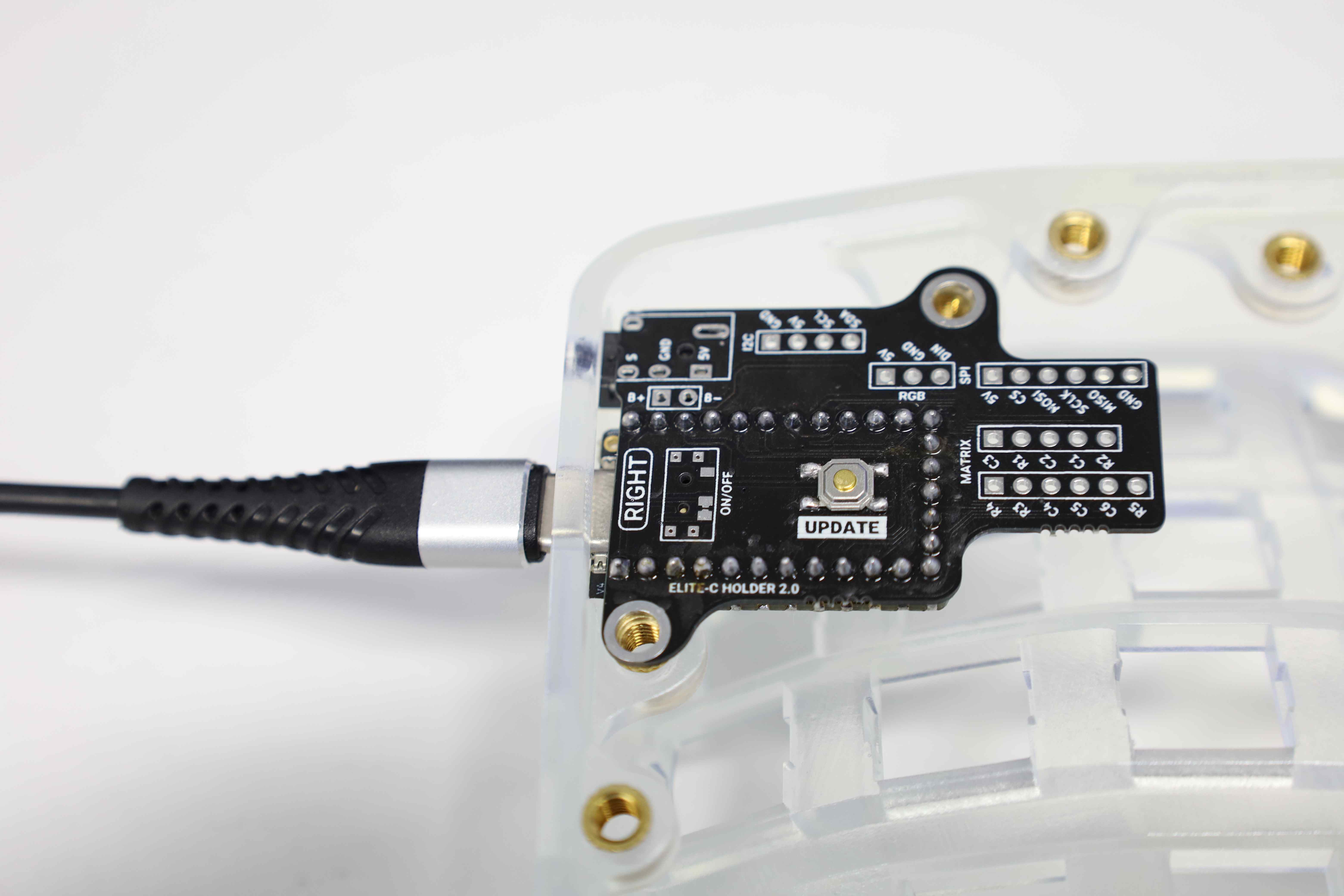
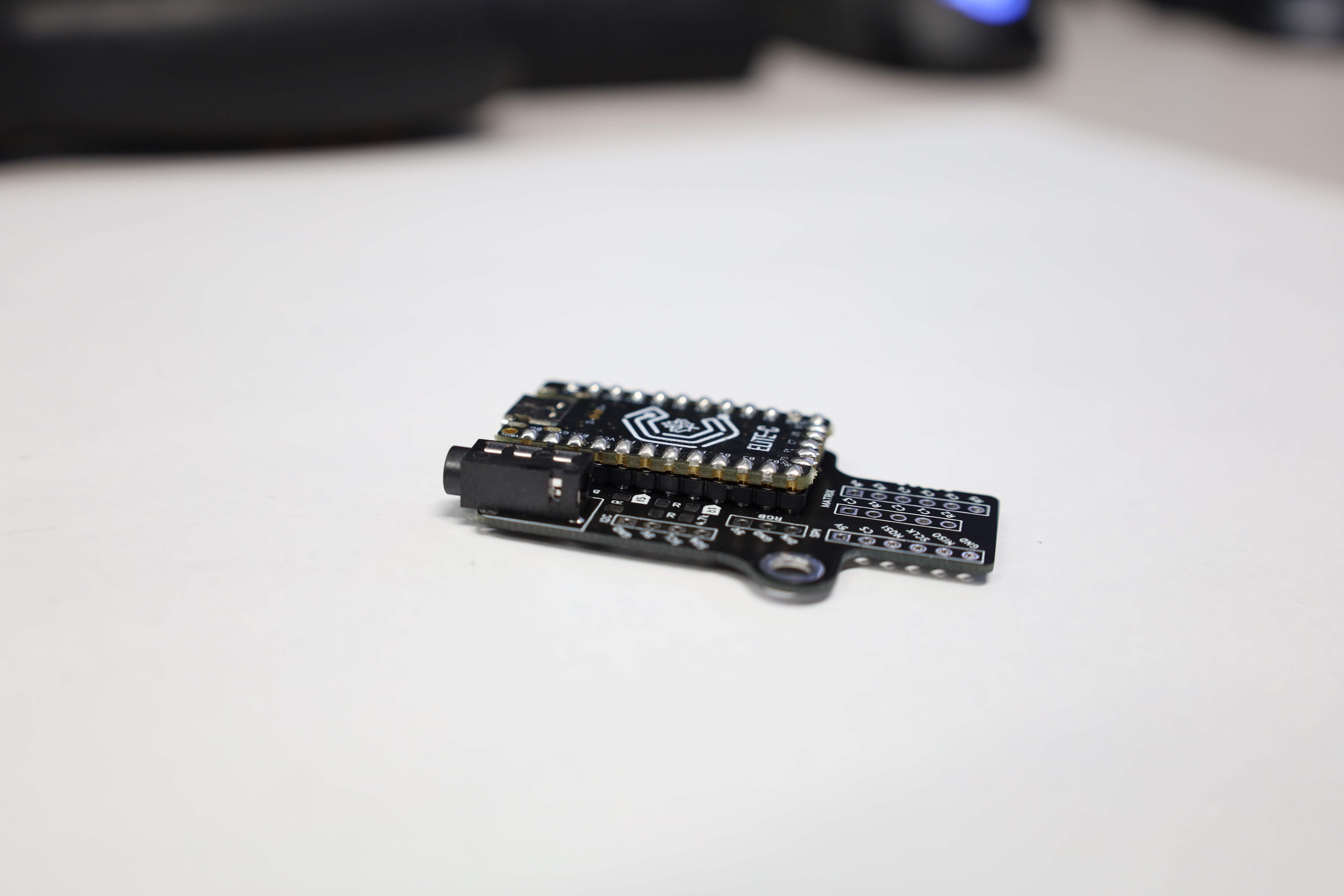
With the Elite C setup, only the reset button, as well as the TRRS jack remain.
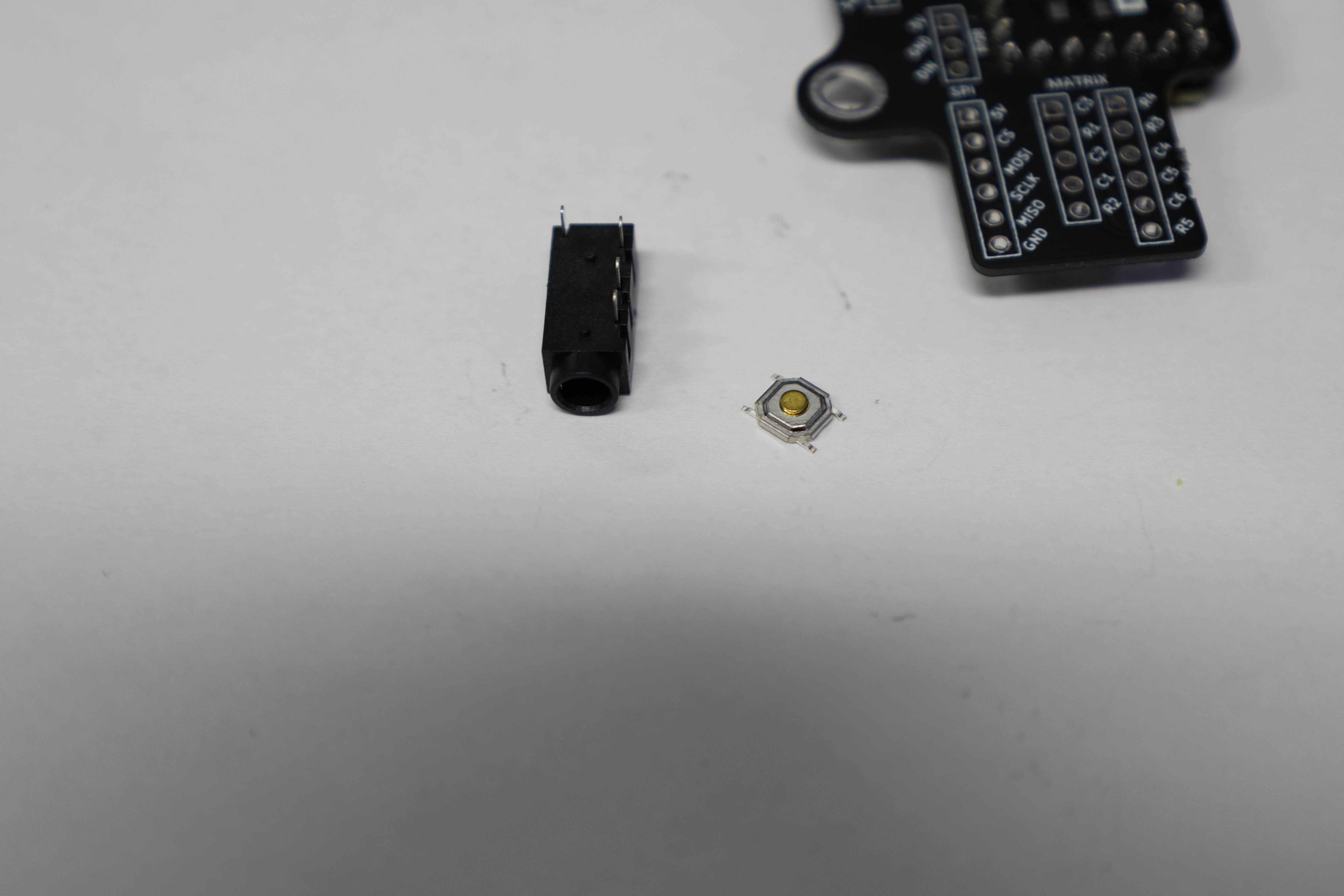
Soldering the button is straightforward.
The TRRS jack, however, is better installed directly into the case. Then, the shield is made to fit with the position of the jack, while at the same time aligning the USB C hole in the case. Just to be sure, it might be desirable to also plug in the cable to make sure that everything is aligned toward the end goal of the build.
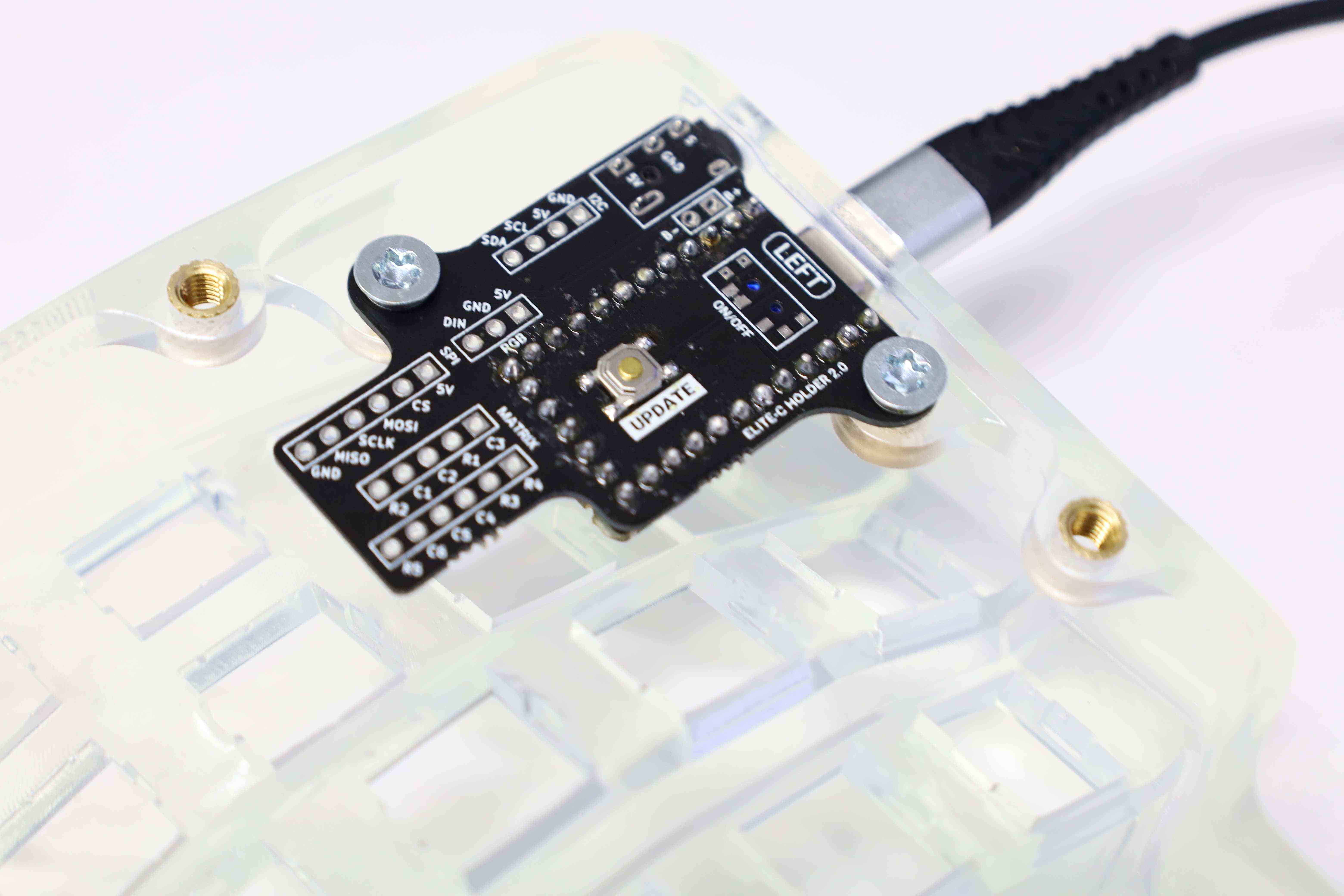
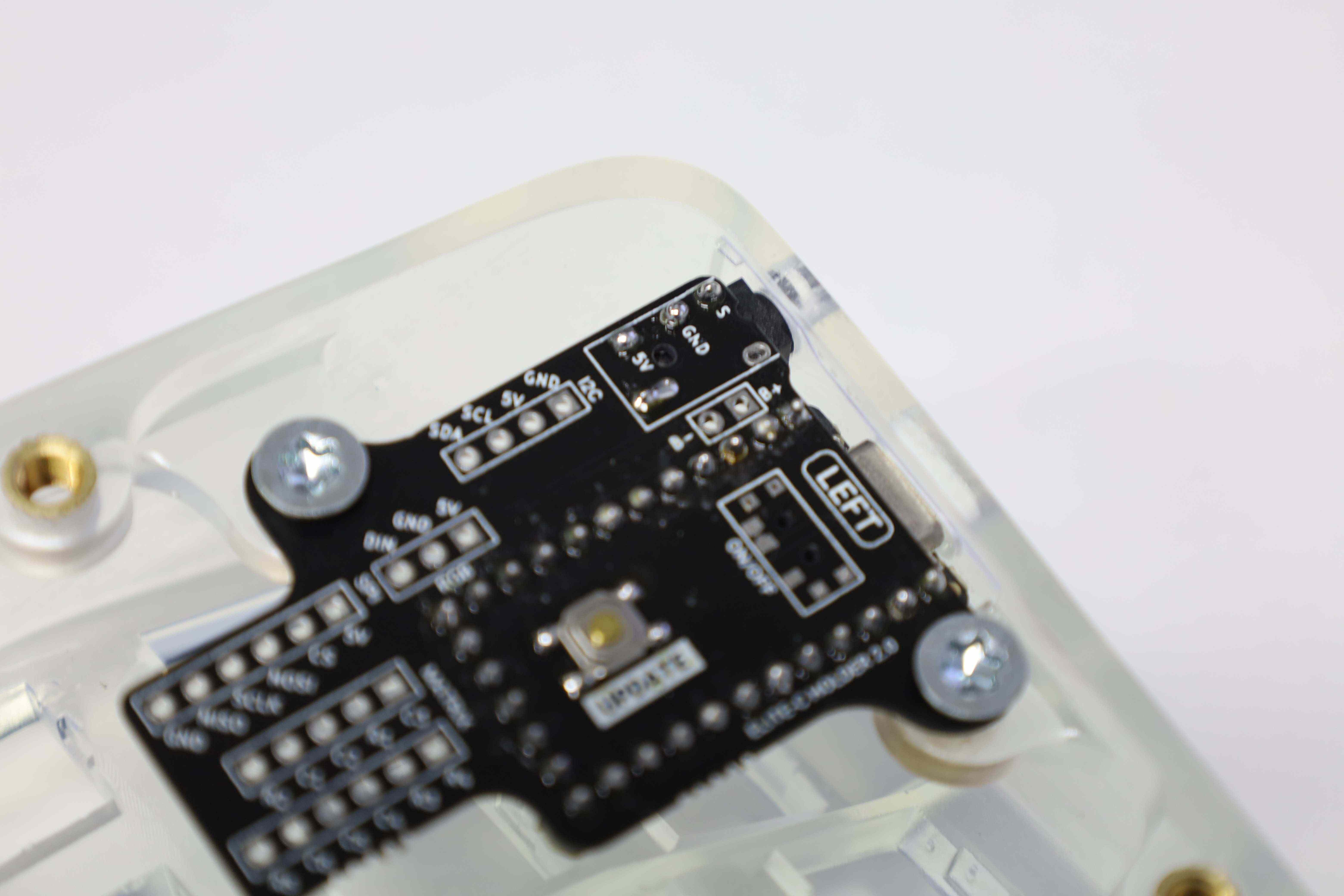
The MCU shield is now ready to be incorporated with the other parts of the board.

The build guide provides the details on how to solder the ribbon (and potentially RGB) cables going from the main PCB to the MCU shield. For Shield v2, it suffices to align the legends on the main board and the MCU shield. For the Shield v1, the build guide provides the correspondence between the legends on the PCB, and the ones on the Elite C where the ribbon cables have to be soldered directly.
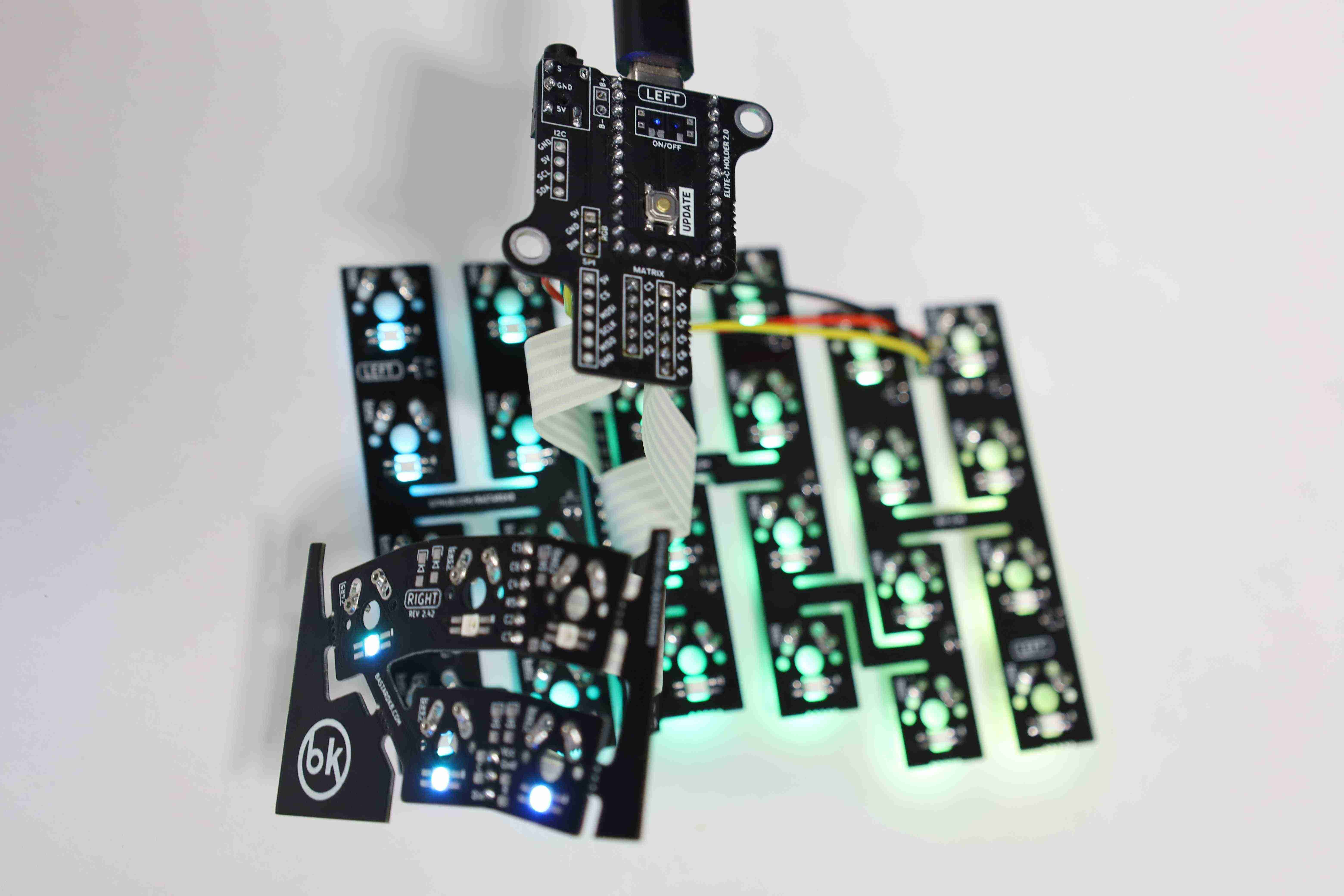
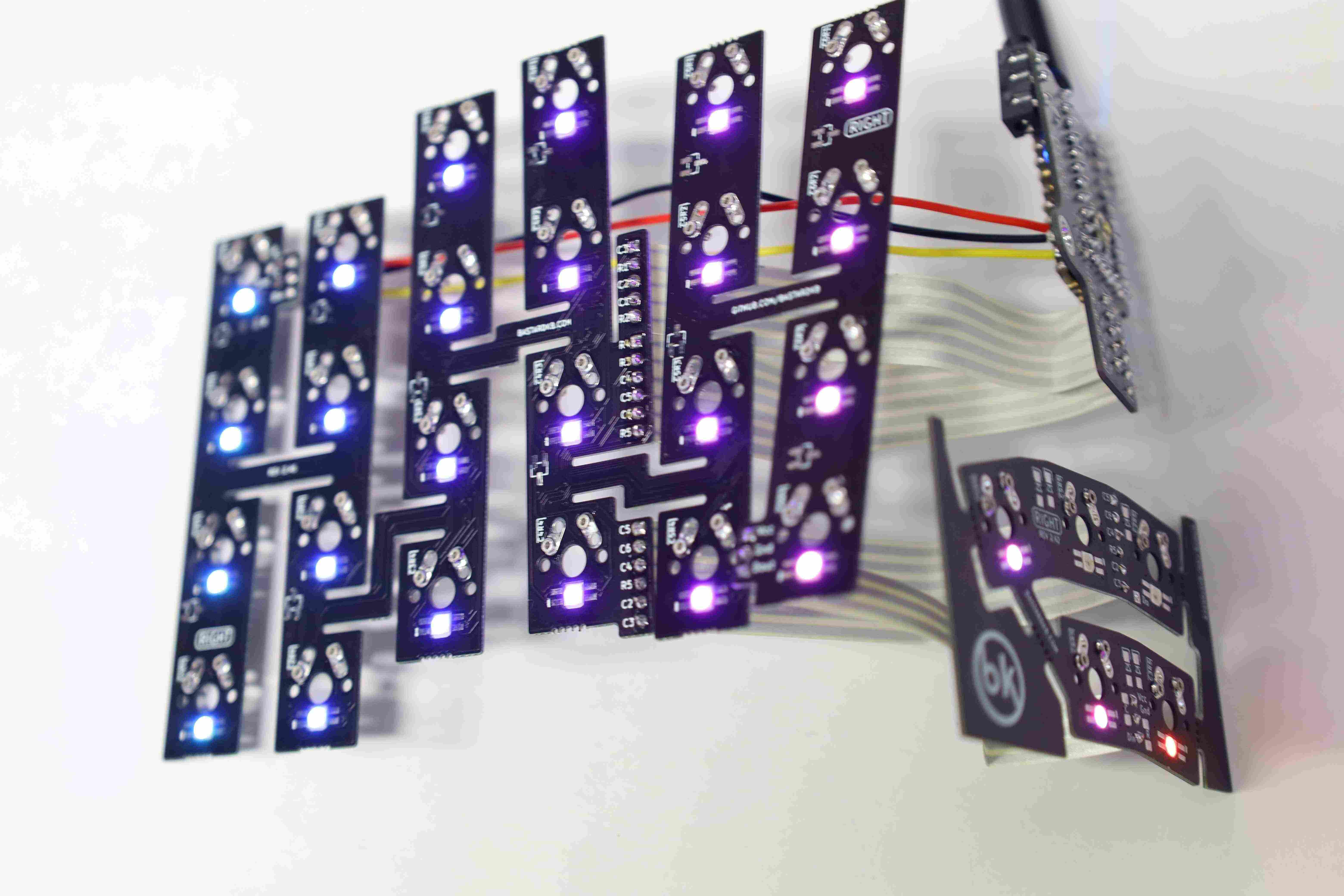
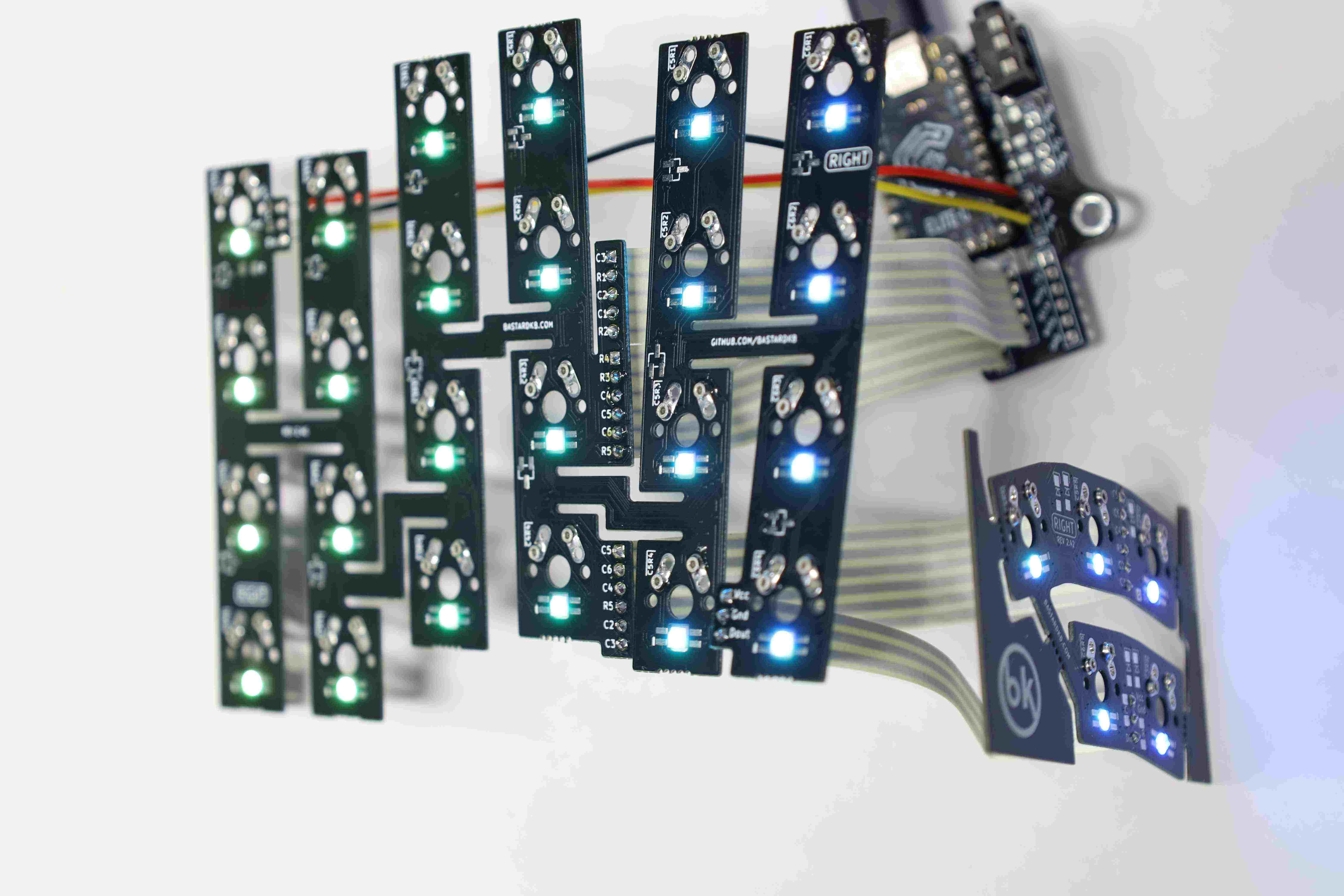
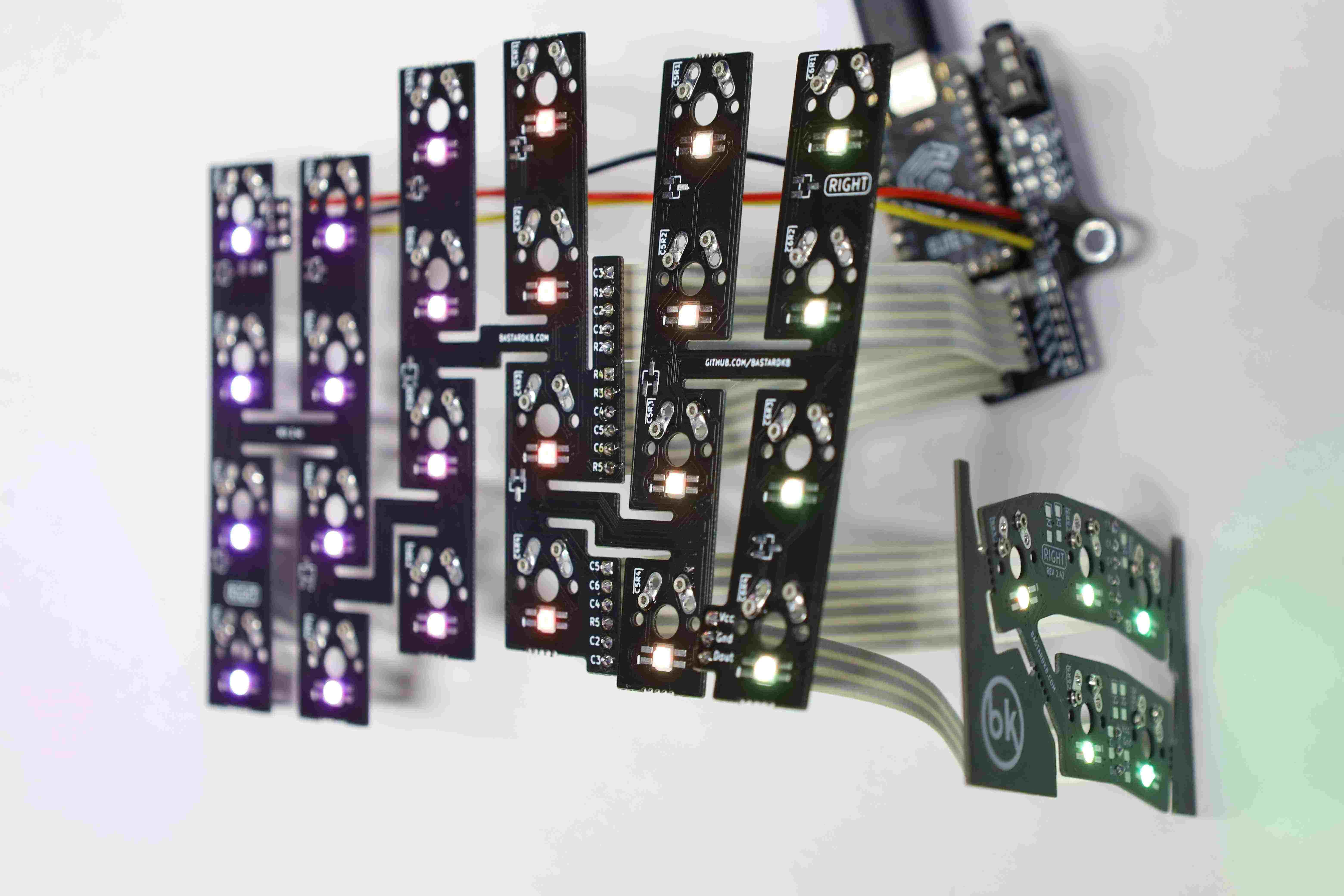
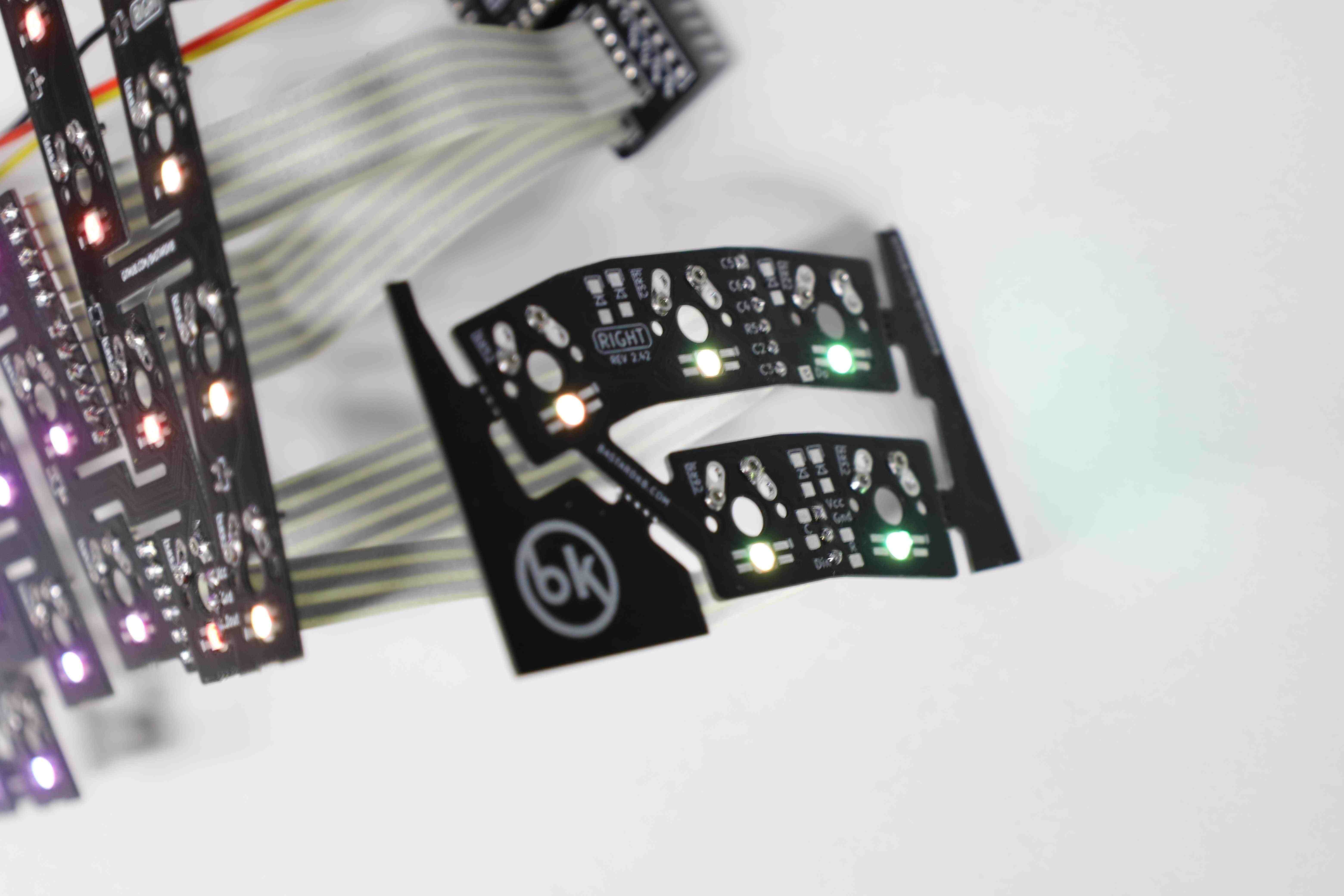
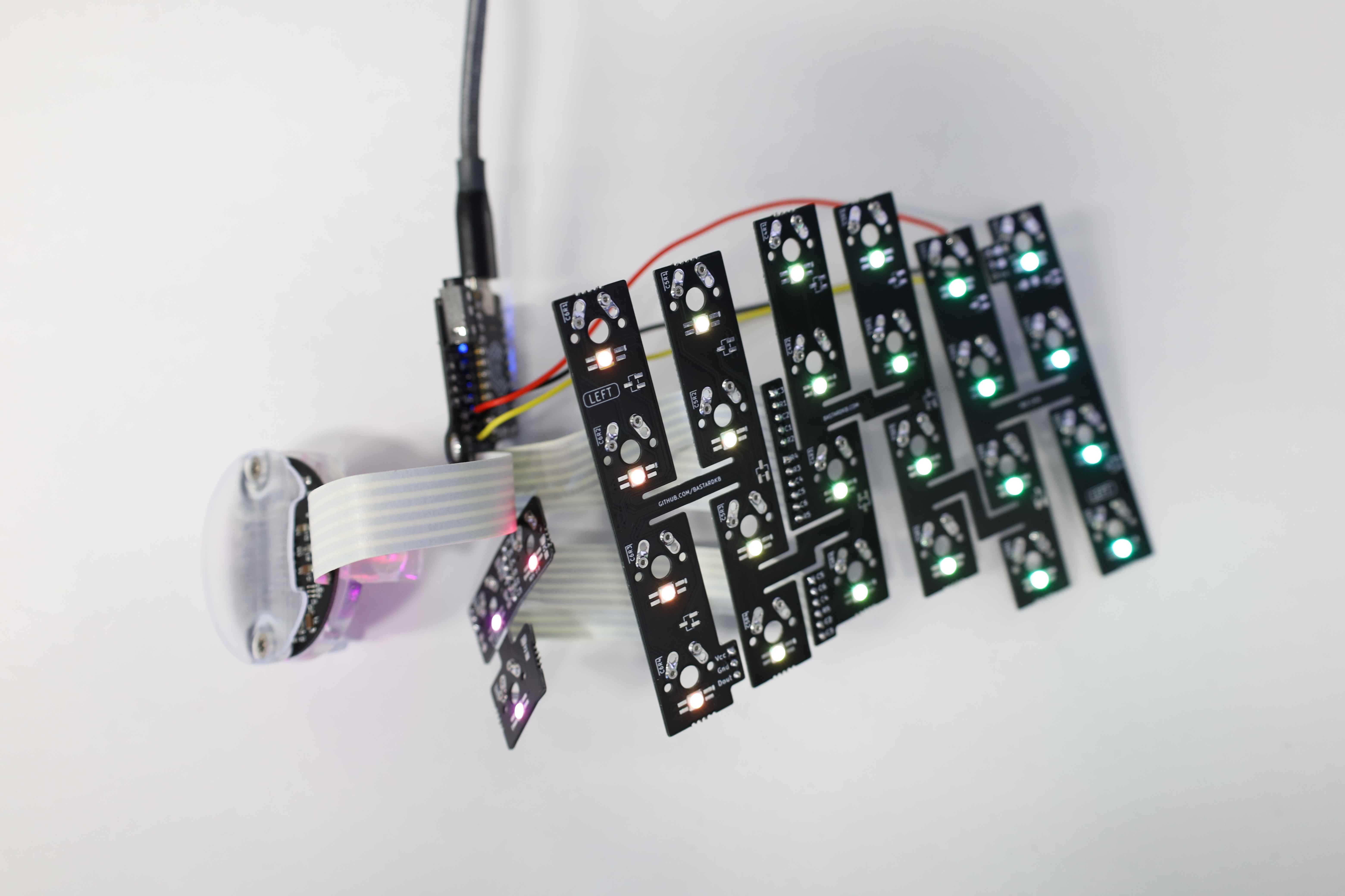
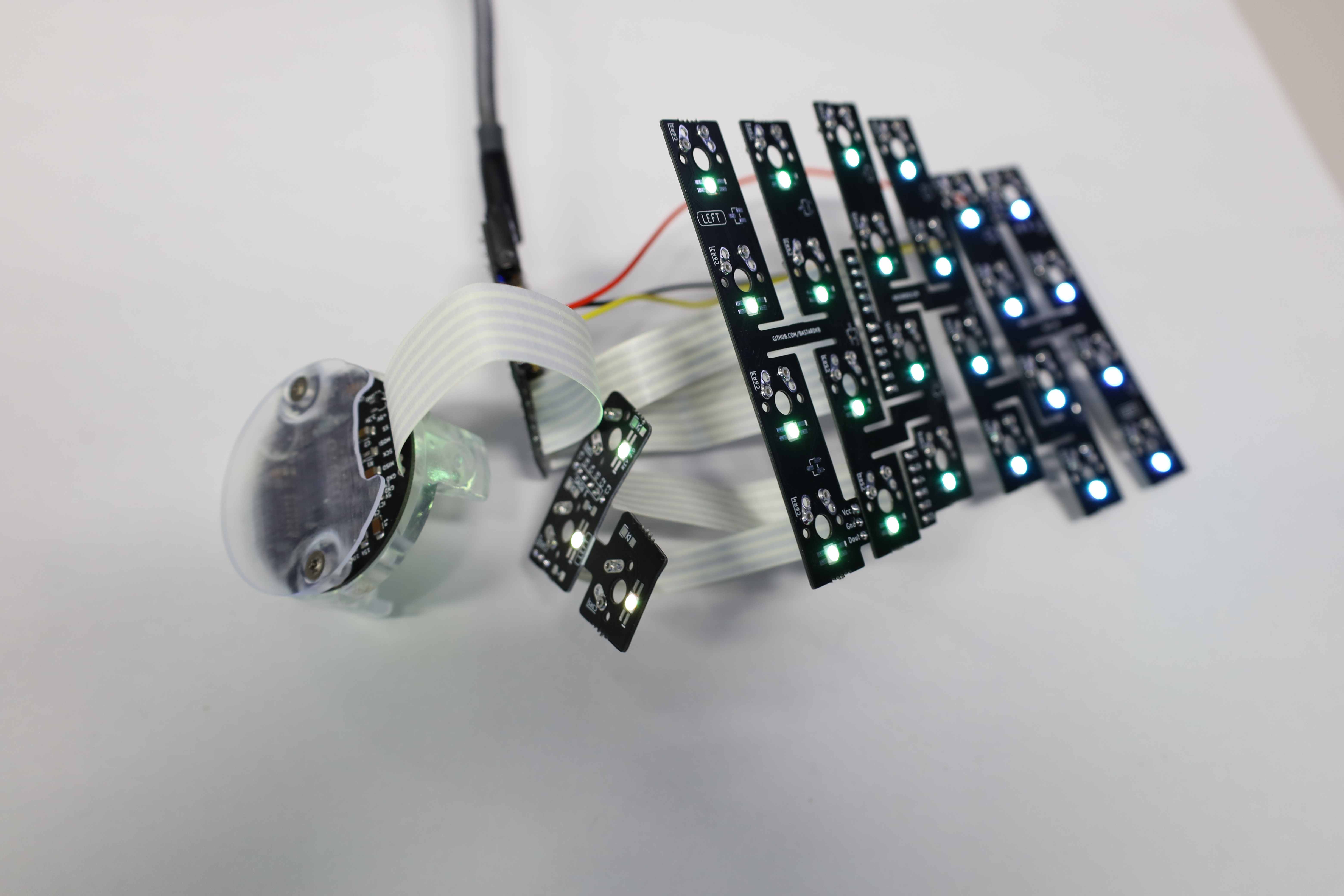
3.7 Preliminary testing
At this stage, it is worth testing the assembled board to make sure that all the keys and the RGB LED (if installed) work. The RGB should light up as soon as the USB C cable is plugged into the MCU. During this build, we can observe that two of the LED on the thumb cluster were not working properly. Carefully replacing them with new ones did the trick.
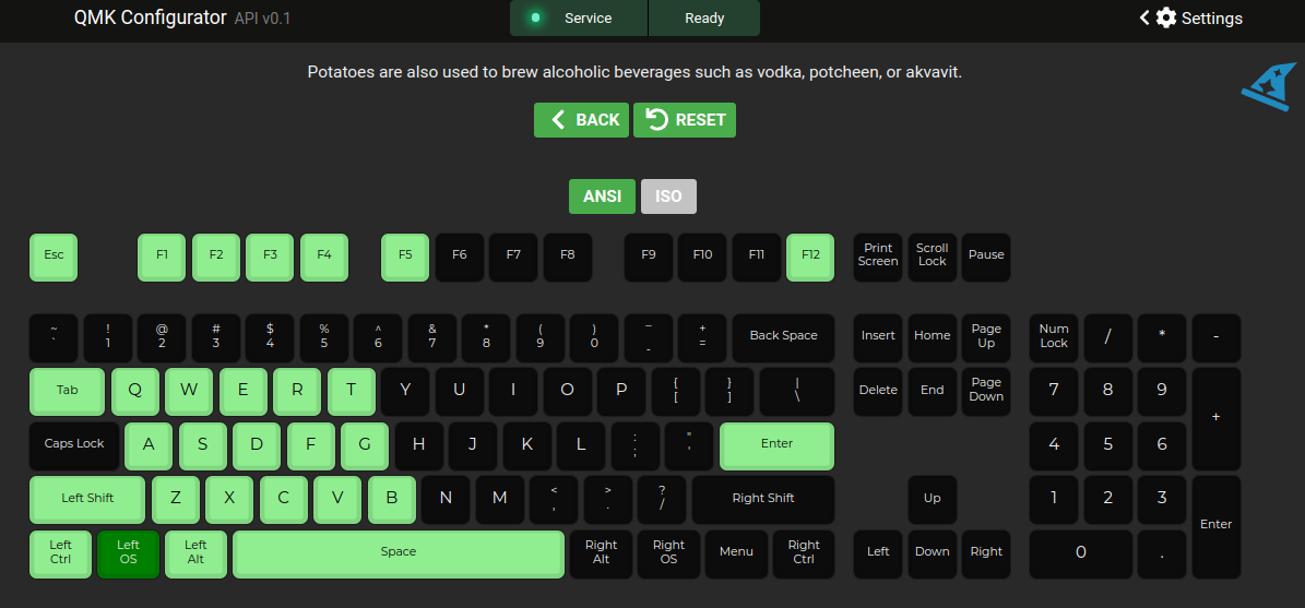
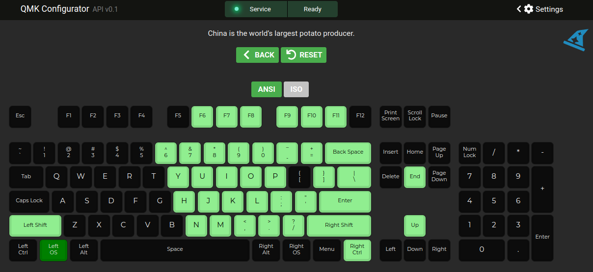
To test the key, one might first need to flash either the default or a custom firmware that allows checking that all the keys on this site are working. (Note that Elite C shipped with the kit likely have the default firmware flashed by default. If it was sourced from another party, however, the firmware will need to be flashed manually.) This can be done by manually shorting the holes for each key switch slot with a conductive tool, and checking that the corresponding keystroke is properly registered. To this end, a tool such as the QMK Configurator’s test feature might come in handy


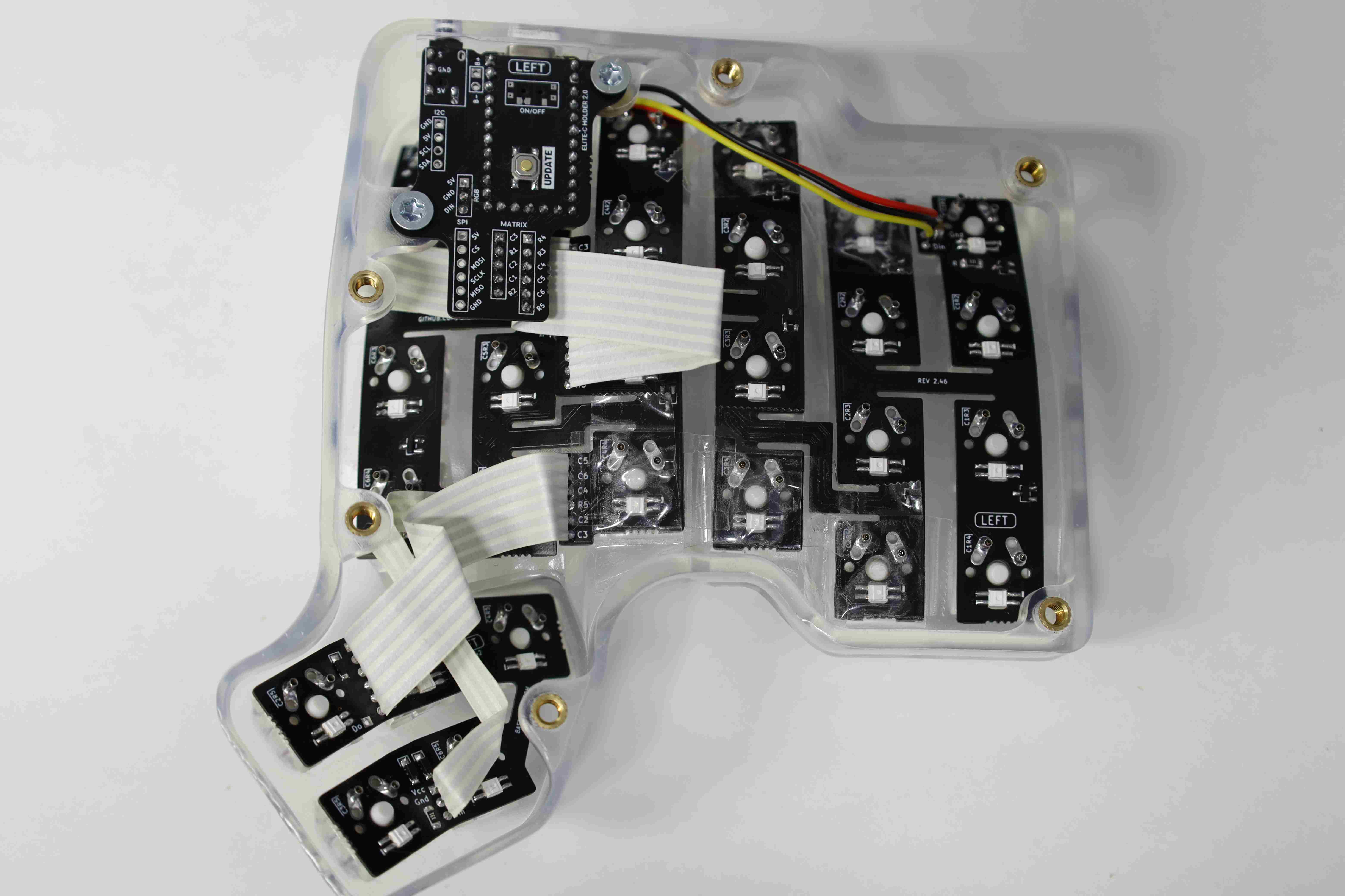
3.8 Case assembly
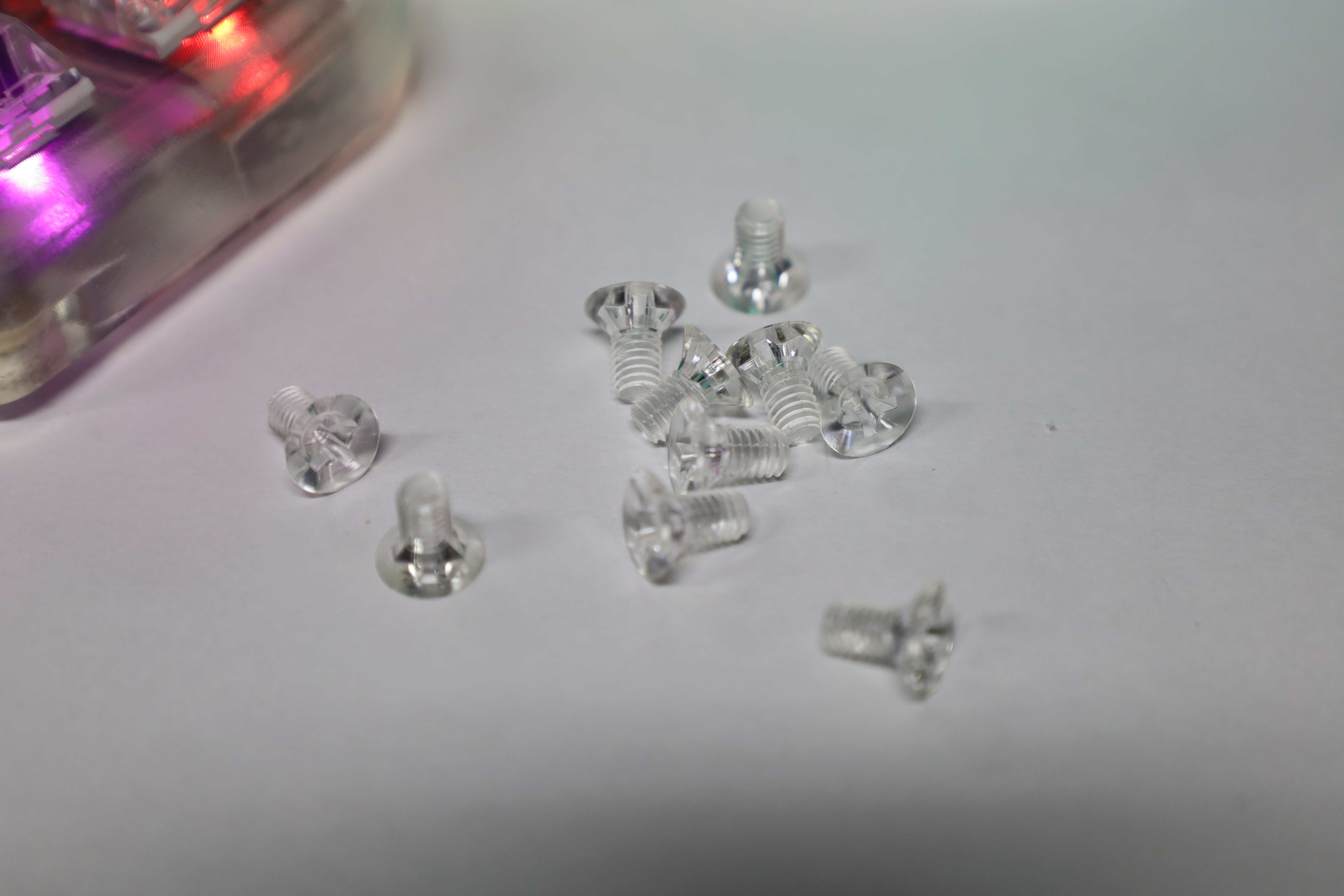
Once it is ascertained that the electronics are working properly, the next step is to combine them with the case. This is also a good time to clean up the solder joint and any remaining flux with some isopropyl alcohol (IPA).
To complement the clear 3D printed case, some clear resin screws were also sourced.
As mentioned in the Mill-Max installation section, the top and bottom rows’ flexible PCBs are prone to lose contact with the switches which are supposed to hold said PCBs to the case. This was remediated by applying a generous amount of gorilla tape, as to not alter the transparent aesthetic too much. While hot glue is also another viable solution, it is not as aestheticaly clean as the gorilla tape variant: the hot glue blob stands out through the clear case.
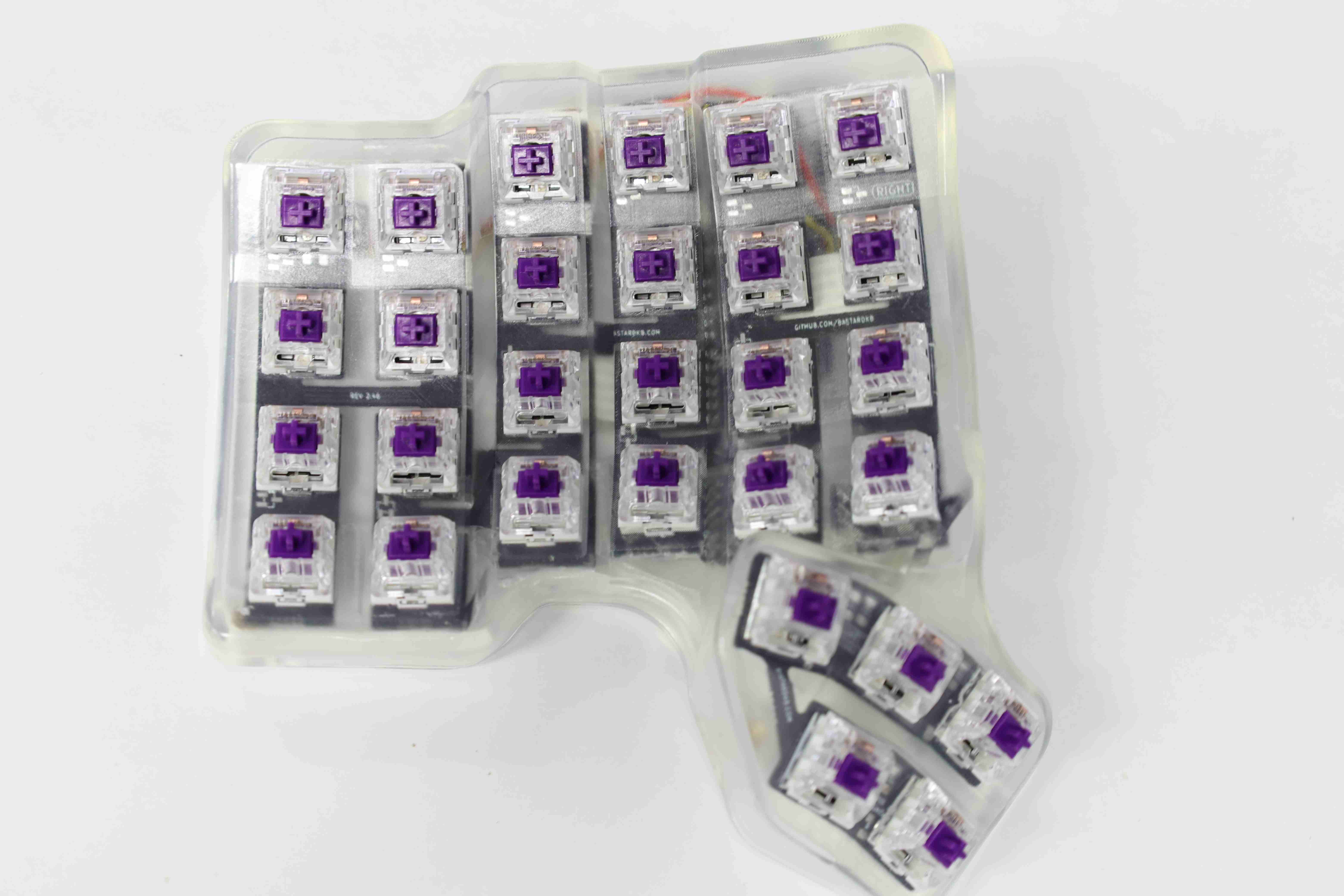
While mounting the switches, it might also be worth testing once in a while that everything is still working as expected.

Once the switches are mounted and confirmed to work, the bottom of the case can be closed up, either with simple bottom plates, or the 30 degrees tents.

After closing up the case, we test the cable connection and the key switches.


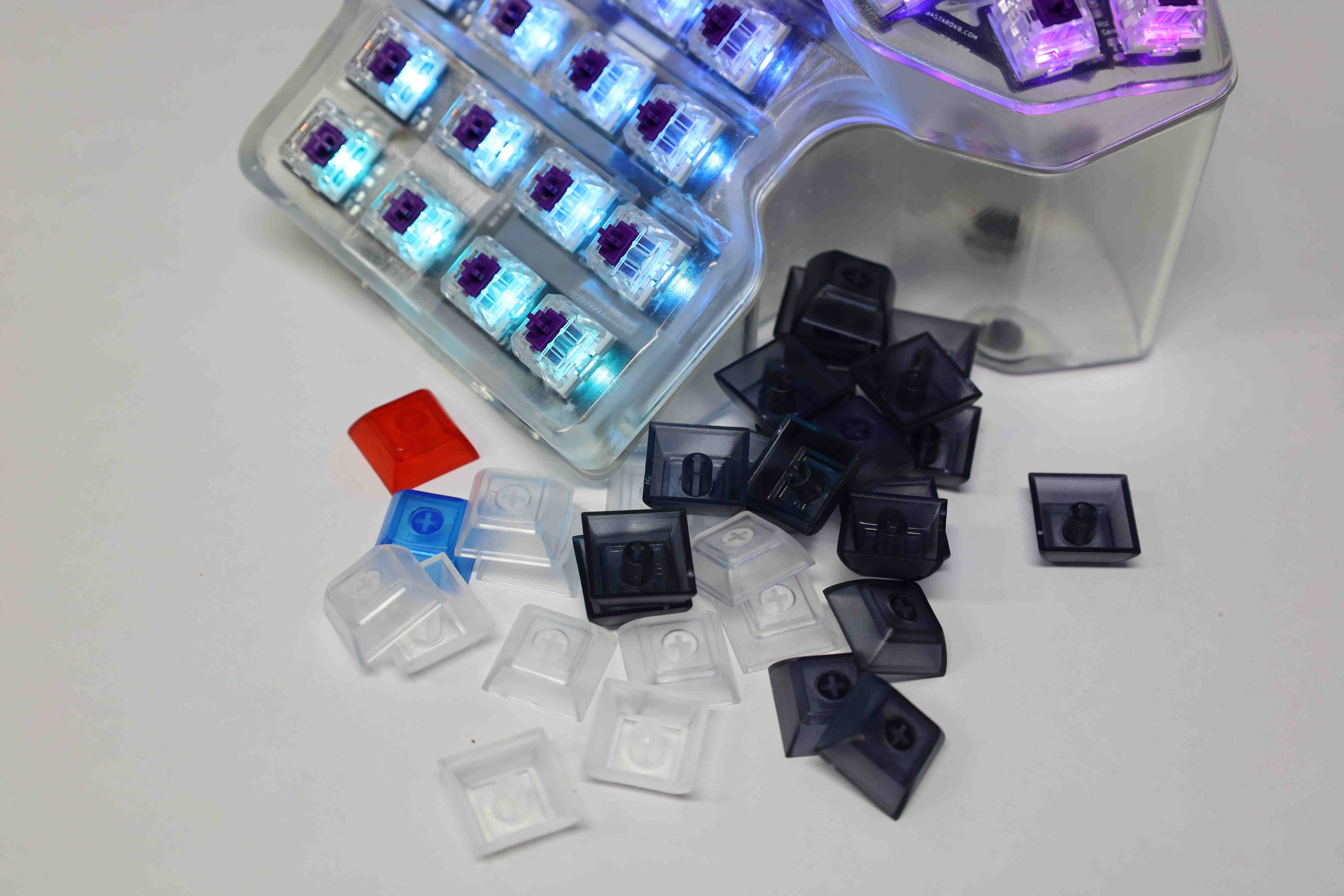
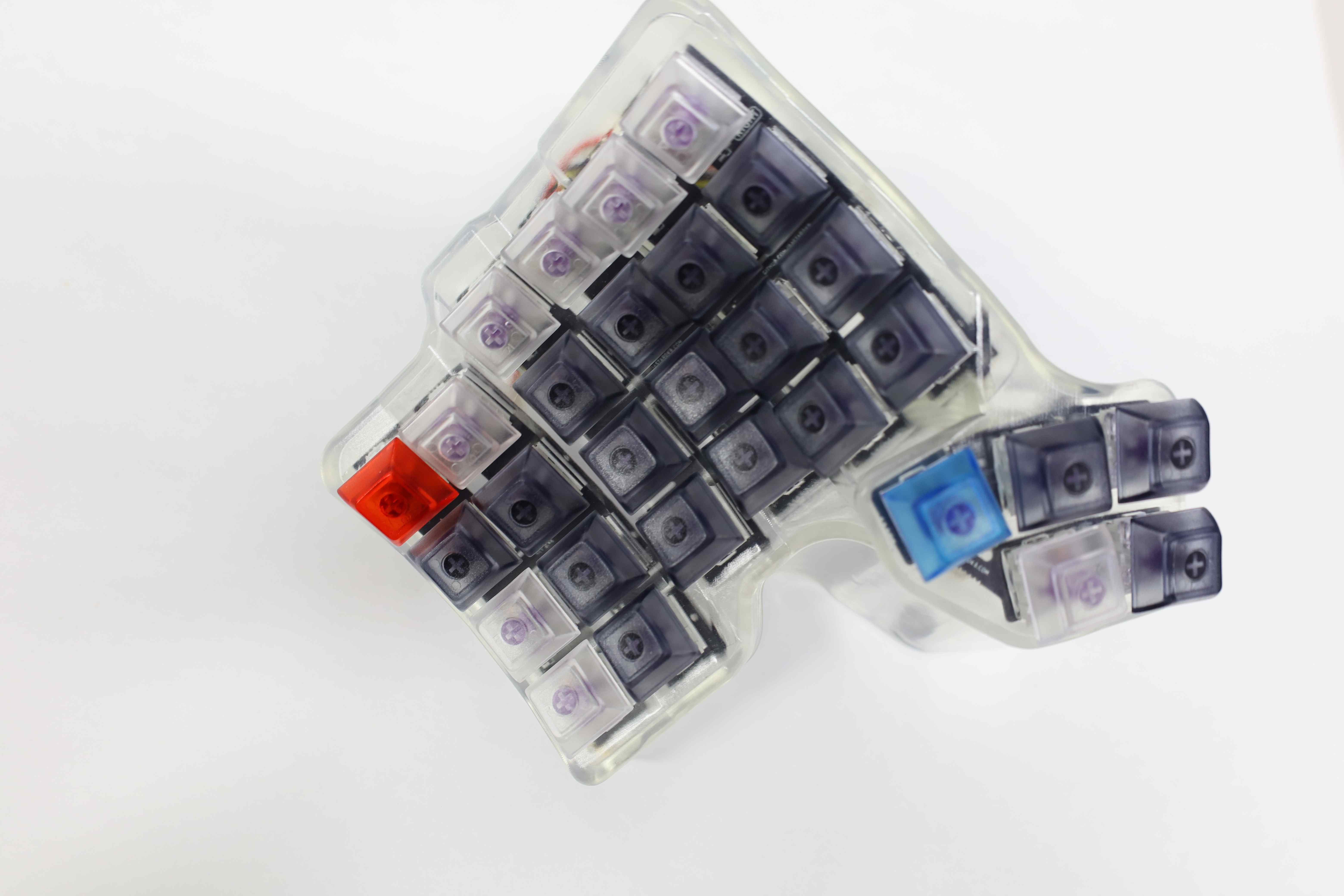
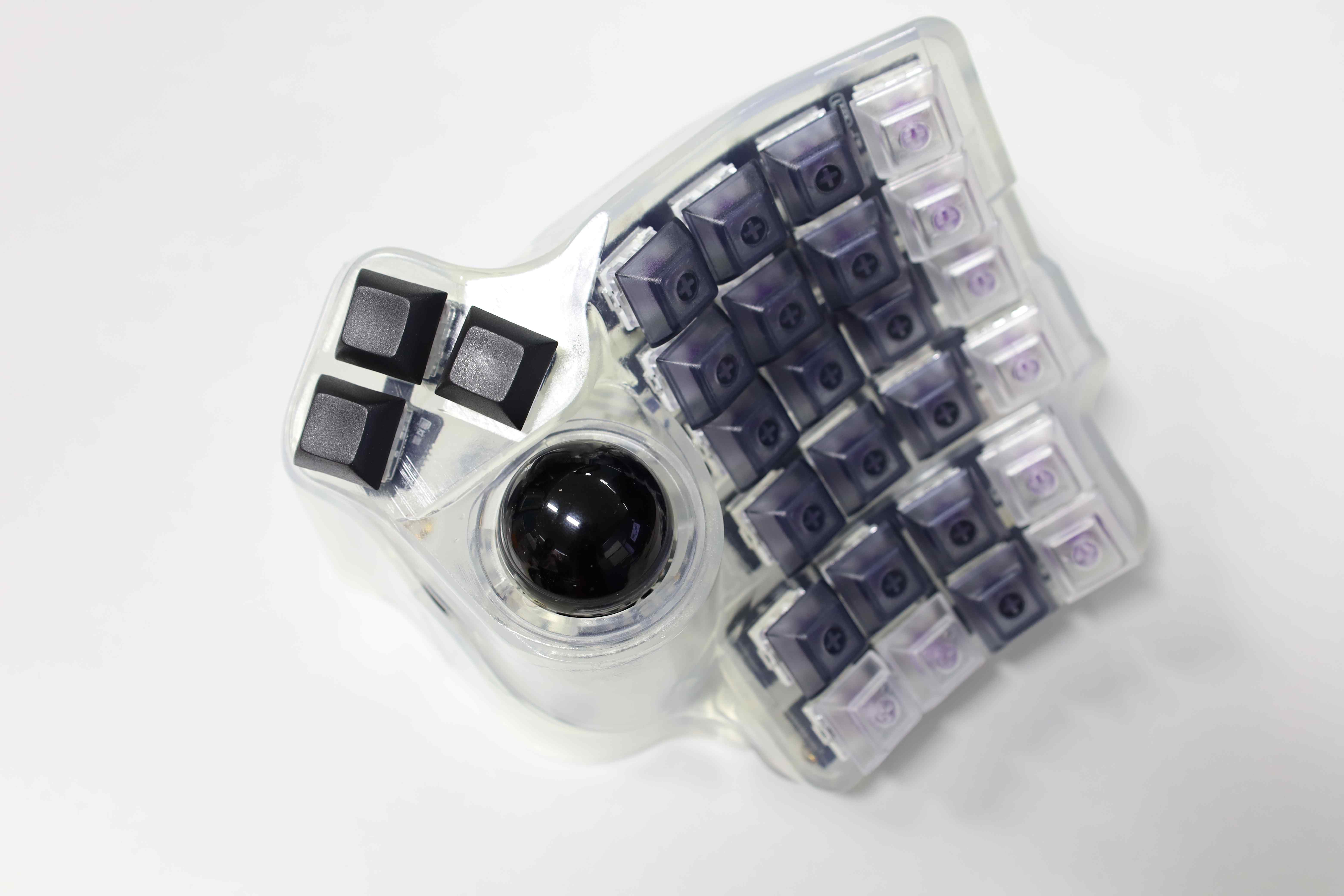
We can finally proceed to the last step of adding the keycaps. This build uses DSA Blank Transluescent caps of various colors, as an attempt to compliment the clear case.


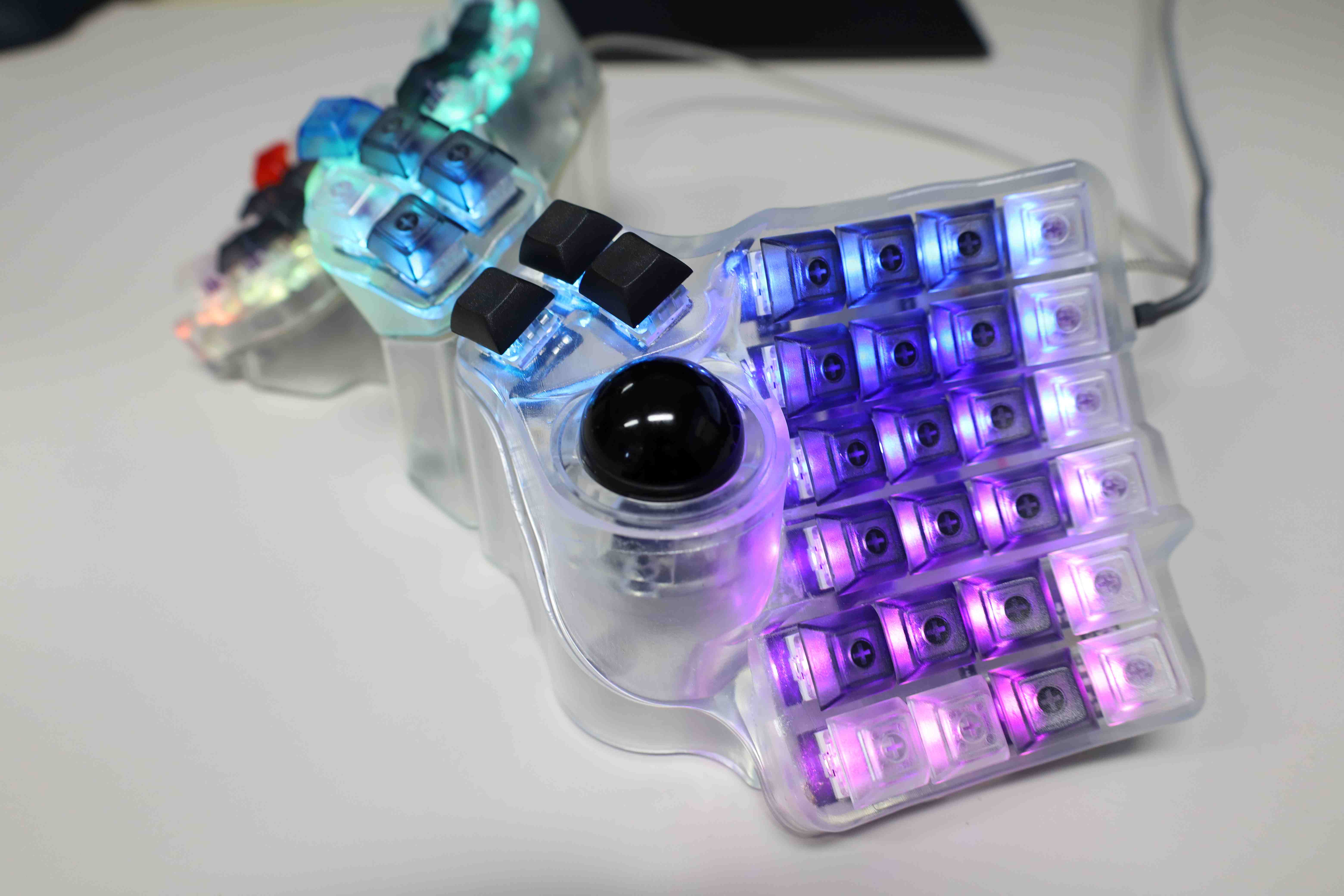
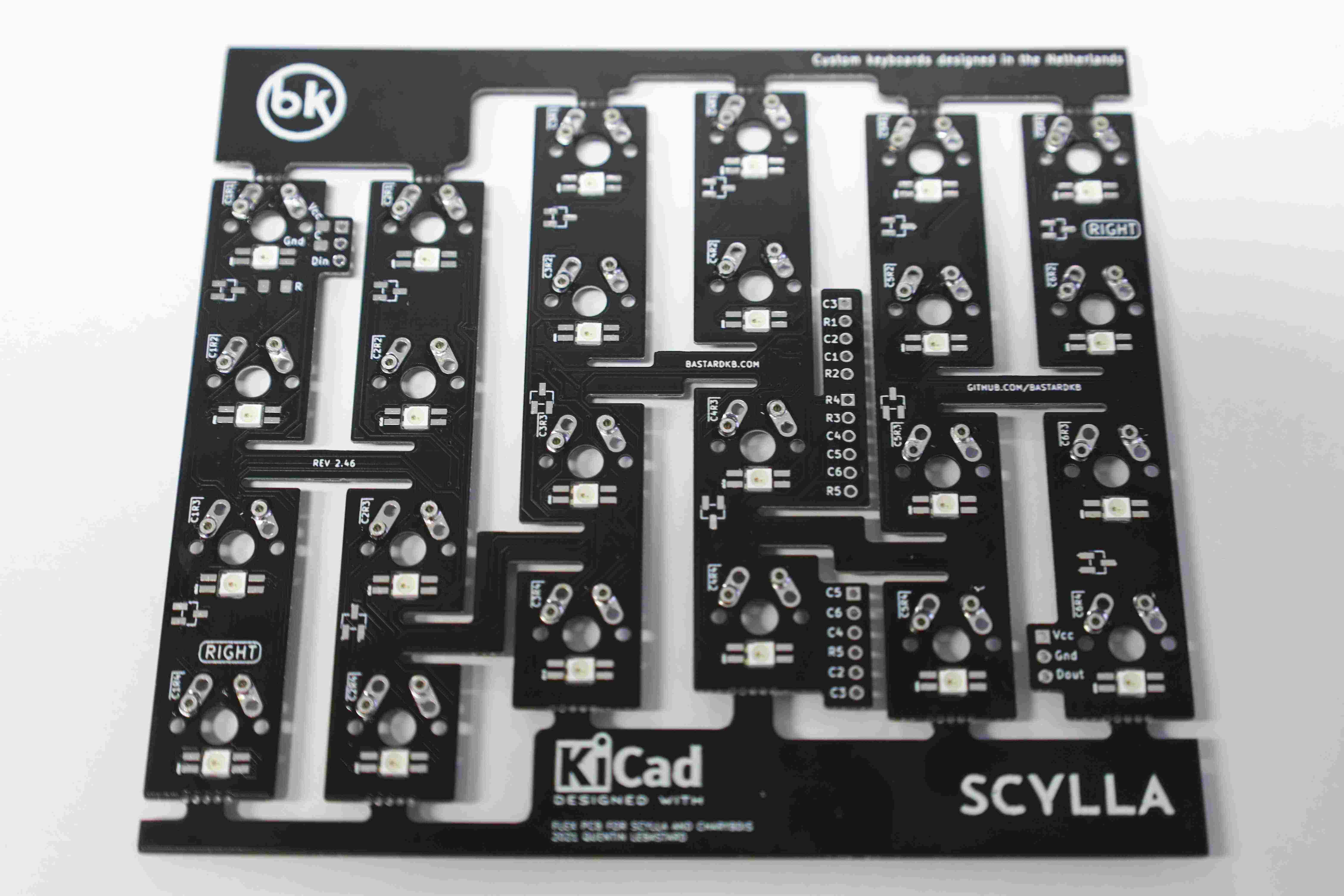
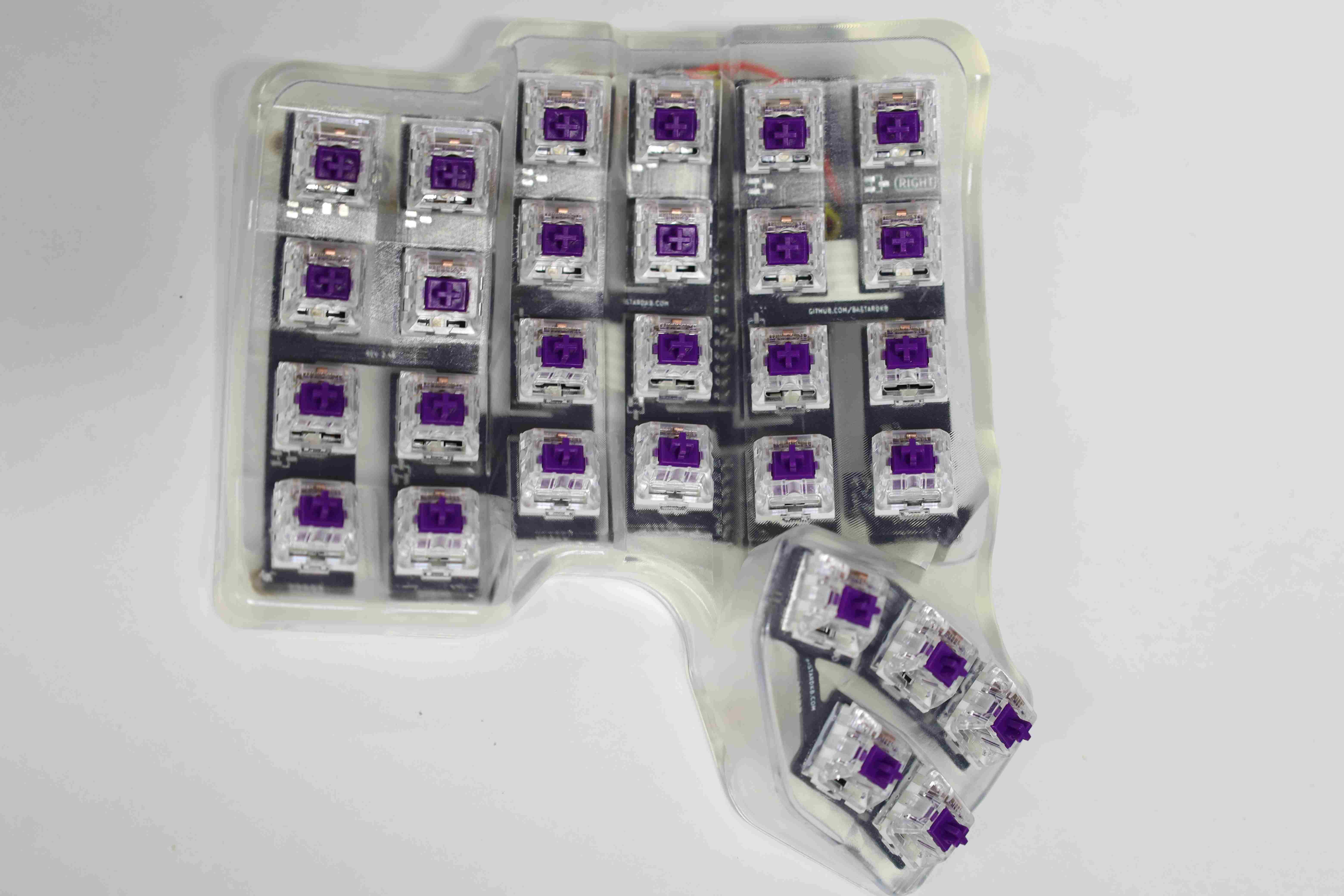
4. Right side: Charybdis
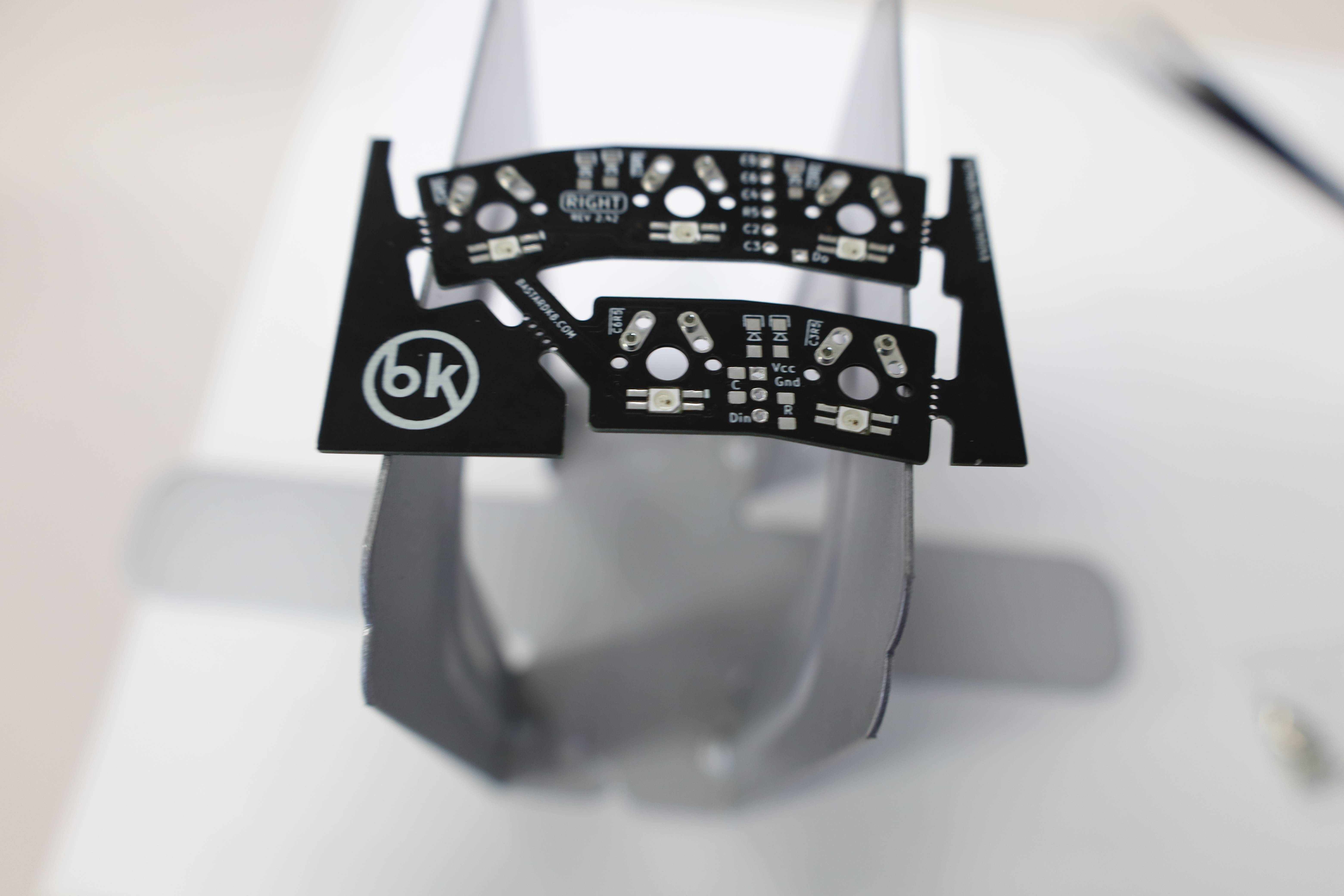
This step is essentially the same as for the Left Scylla side. The crucial difference is the addition of the trackball, which is itself straightforward. Furthermore, the flexible PCBs have to be oriented so that the side labeled as “Right” is the one facing up.

4.1 Installing the diodes
Following the same procedure as for the Left Scylla side, the diodes are soldered on the main and thumb cluster PCB. For the Charybdis side, the thumb cluster has only 3 keys, hence only requiring 3 diodes.
4.2 Installing the RGB components [Optional]
Similar to the Left Scylla half board, 1 capacitator, and 1 resistor are installed on the top left corner of the main PCB, with their designated placement marked with the C and R legends respectively. Moreover, 1 capacitator and 1 resistor are also installed on the thumb cluster at the designated locations. Finally, the RGB LEDs themselves, 24 for the main PCB, and 3 for the thumb cluster are installed and soldered on.
4.3 Installing Mill-Max sockets for hot-swap [Optional]
The Mill-Max sockets for hot-swappable switches are again installed following the procedure detailed in the Left Scylla Mill-Max installation section, with the following results:

4.4 Ribbon cables and RGB cables
Next, the ribbon cables to link the main PCB with the thumb cluster daughter board, as well as the MCU shield are installed.
4.5 Connecting the thumb cluster
The next step is to connect the right thumb cluster to the appropriate ribbon cables coming from the main PCB while making the legends align. Double checking on the related sub-section on the official build guide is recommended.

4.6 Installing the Elite-C MCU
Keeping the different orientation from the Left Scylla half board, the MCU Shield v2 abridged installation process is as follows:
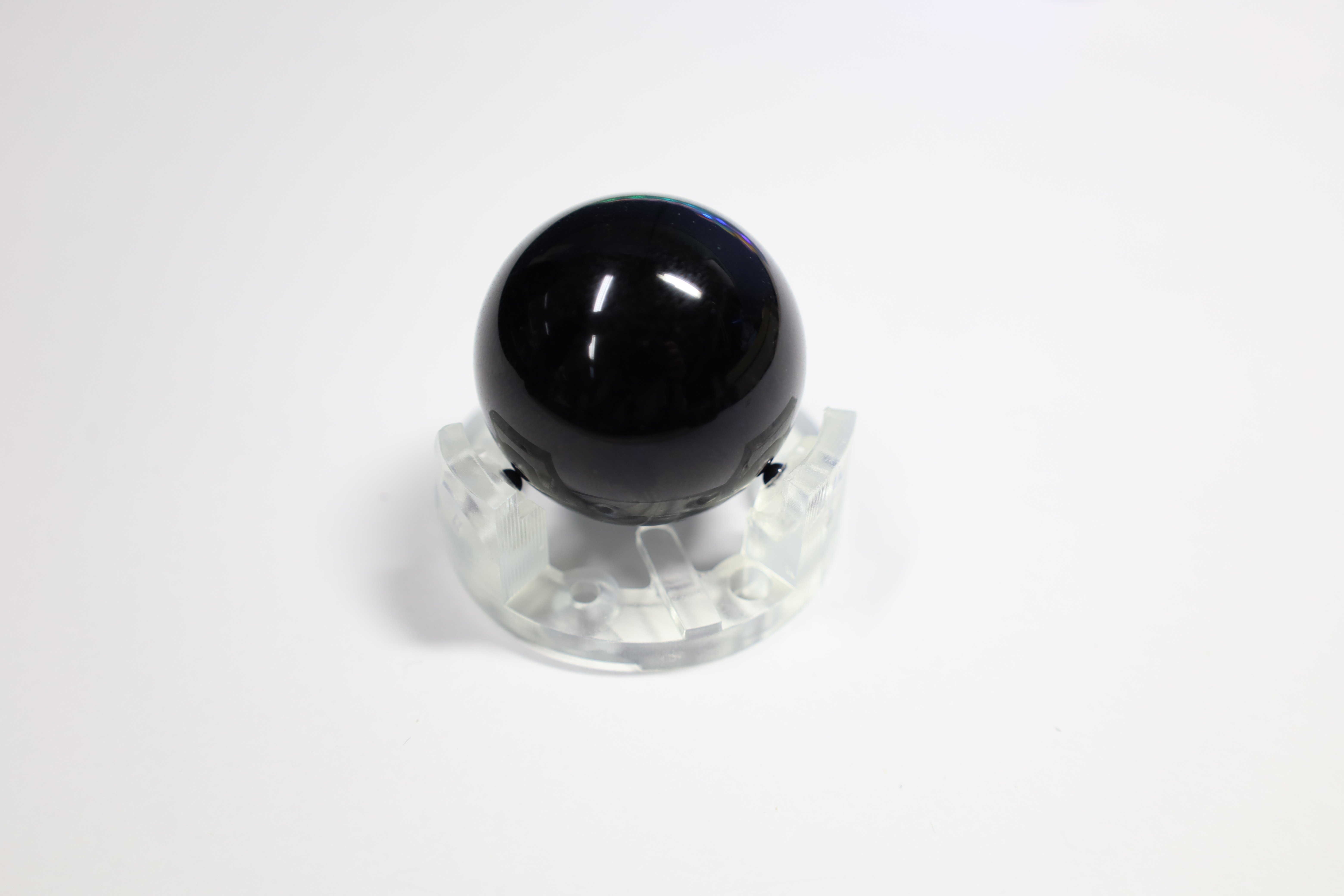
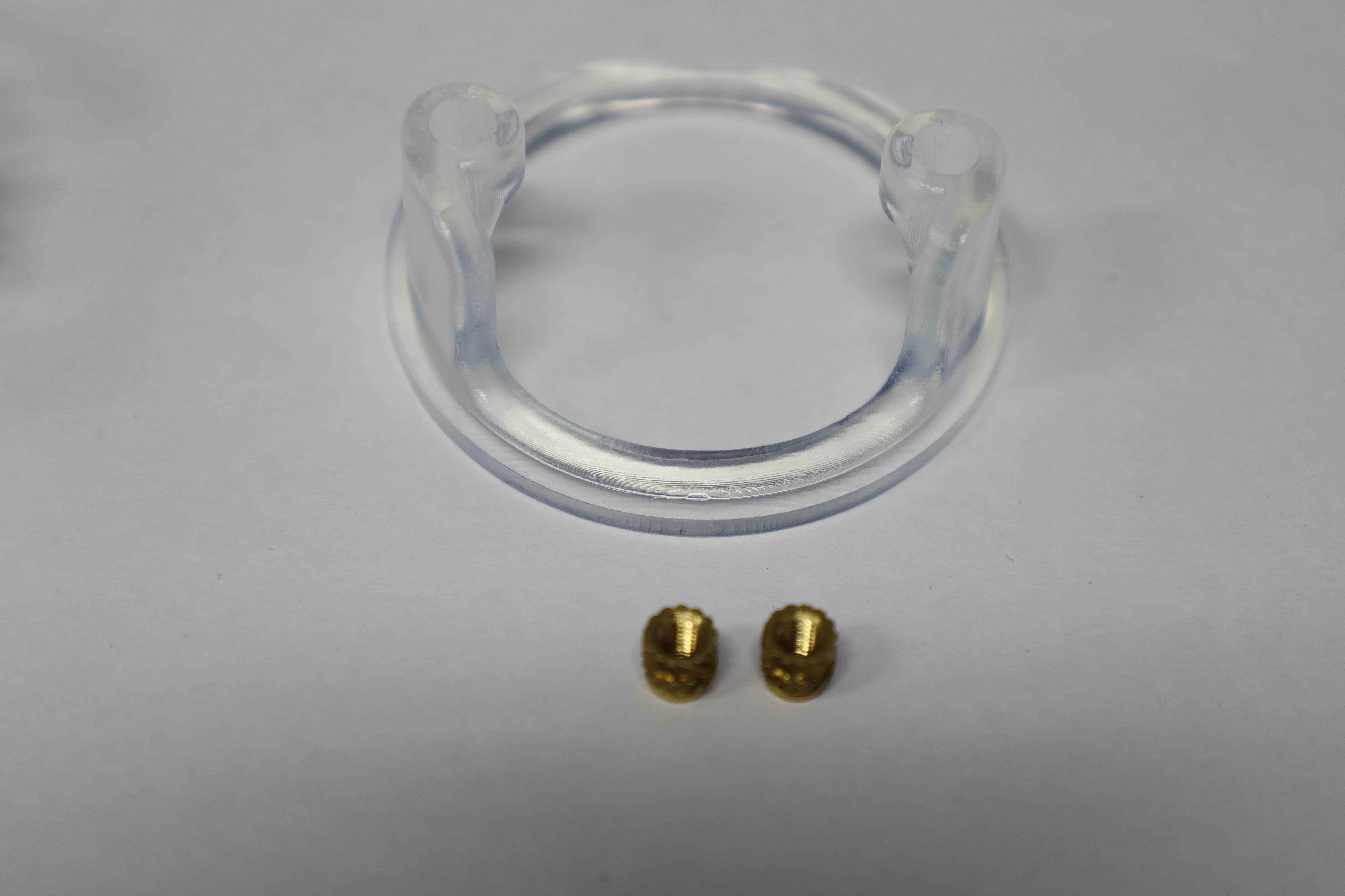
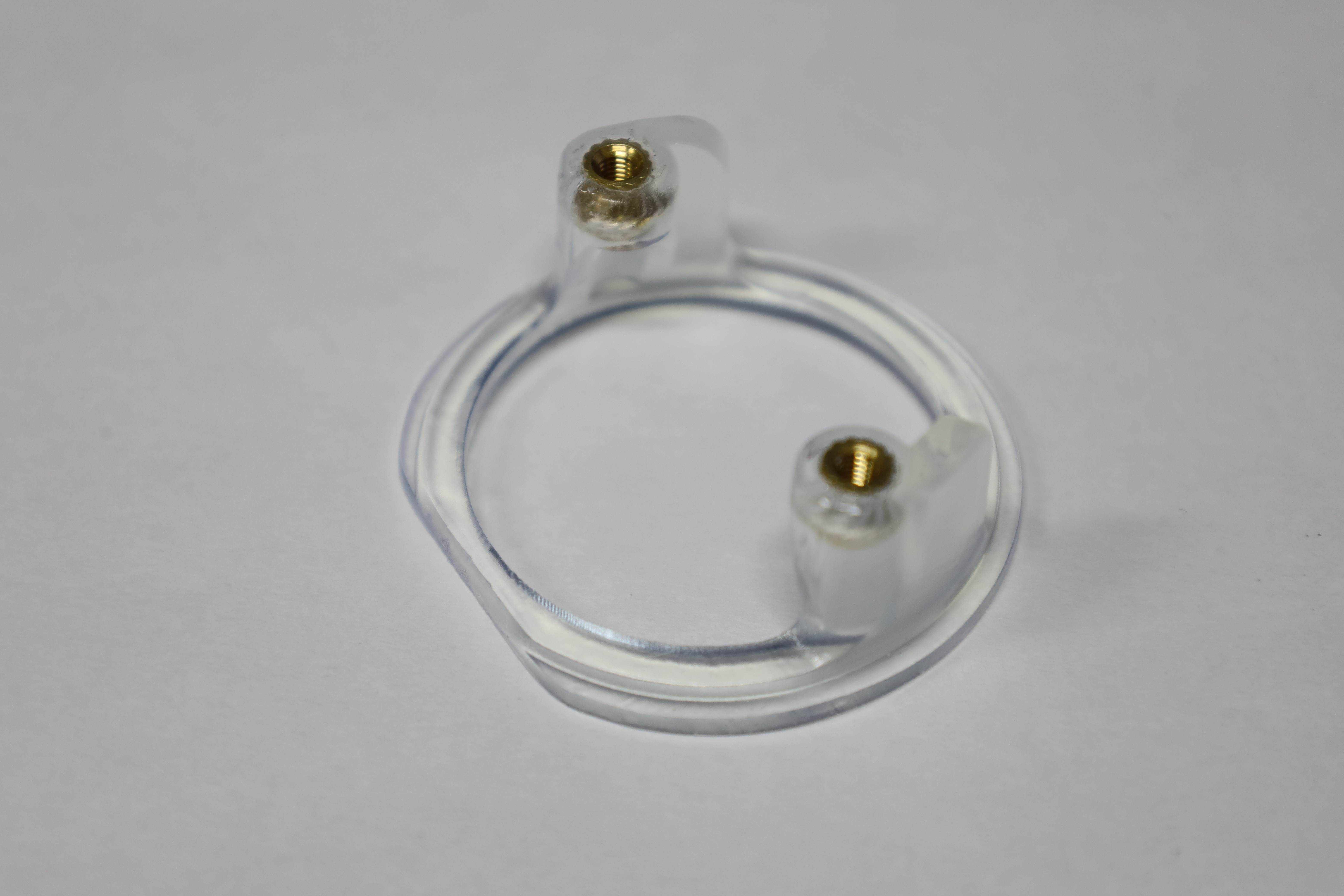
4.7 Installing the trackball sensor
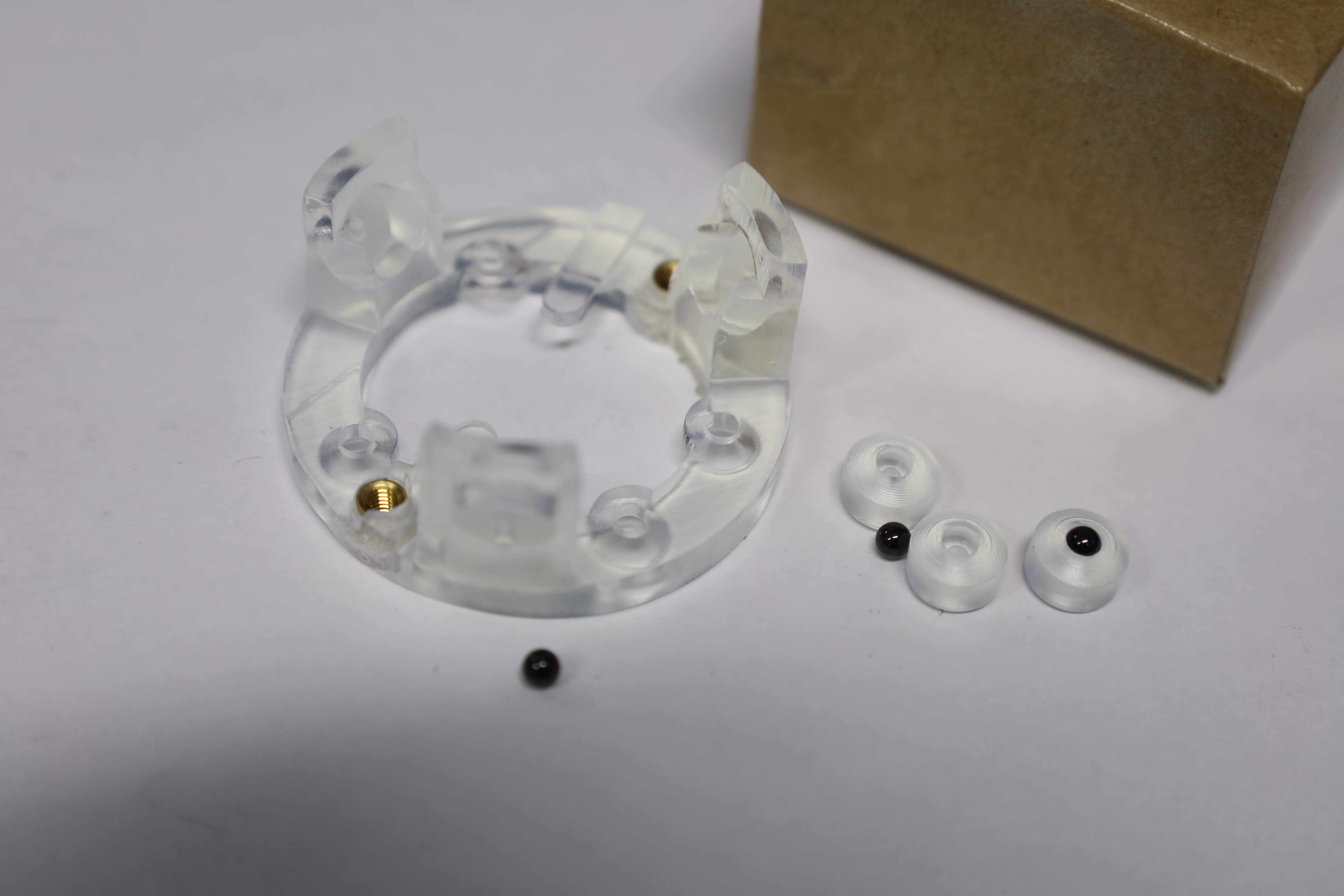
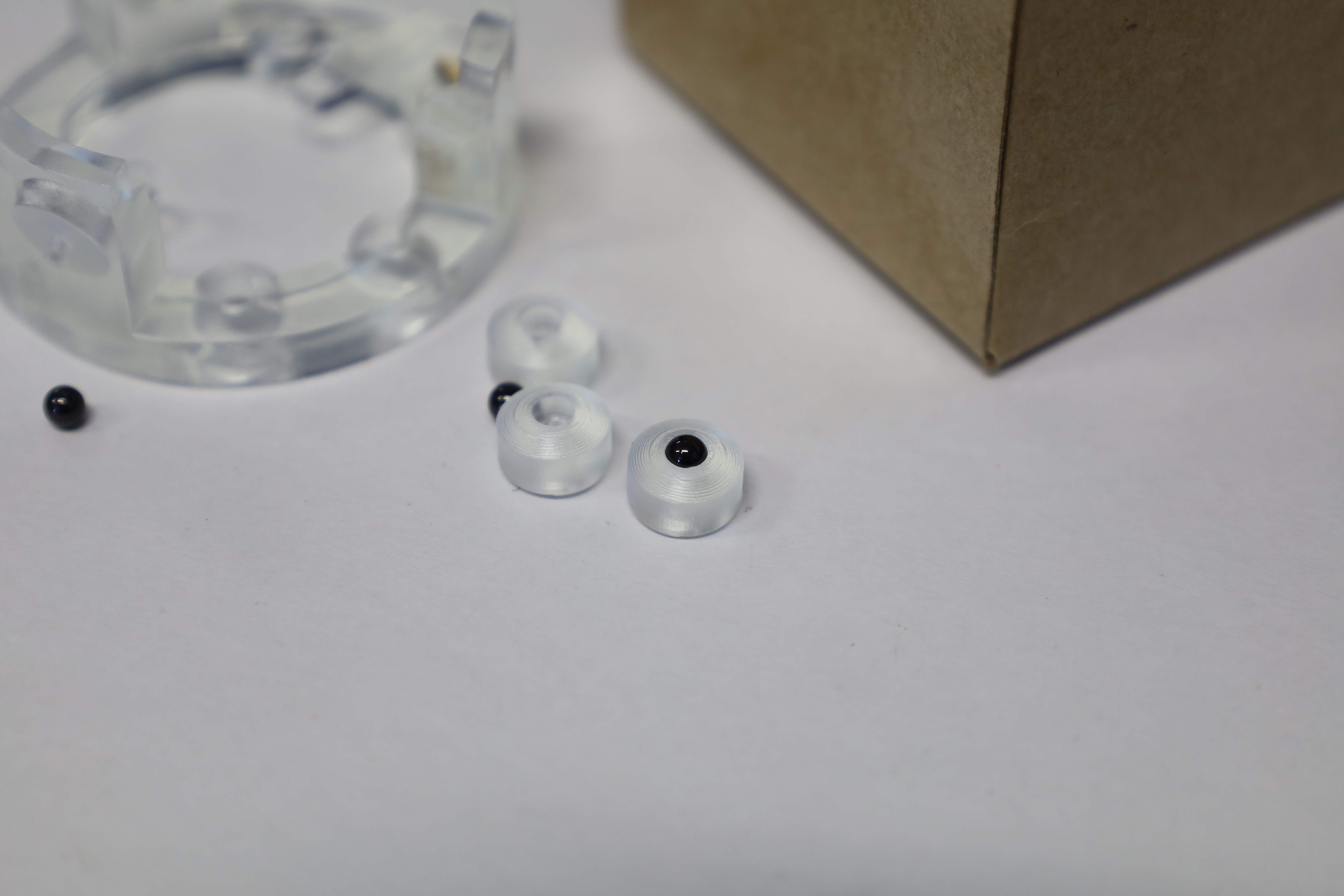
This section is specific to the Right Charybdis half board and outlines the step to install the trackball sensor as well as its holding compartment into the case. This builds uses 3D printed BTU instead of the default bearings, striking a trade-off between smoothness and price.

Note that the sensor board comes with some Kapton tape under the sensor protecting case, which needs to be removed before pursuing the build, as per the official build guide.
As of 2022-04, the 3D printable BTU mod uses 3 small balls to support the trackball in the bottom enclosure of its assembly case. The balls had to be sourced independently. The insertion of the ball into the BTU mod, then the BTU mod into the bottom adapter of the sensor is pretty straightforward. It is a tight fit though, so it might require quite some force to get done.
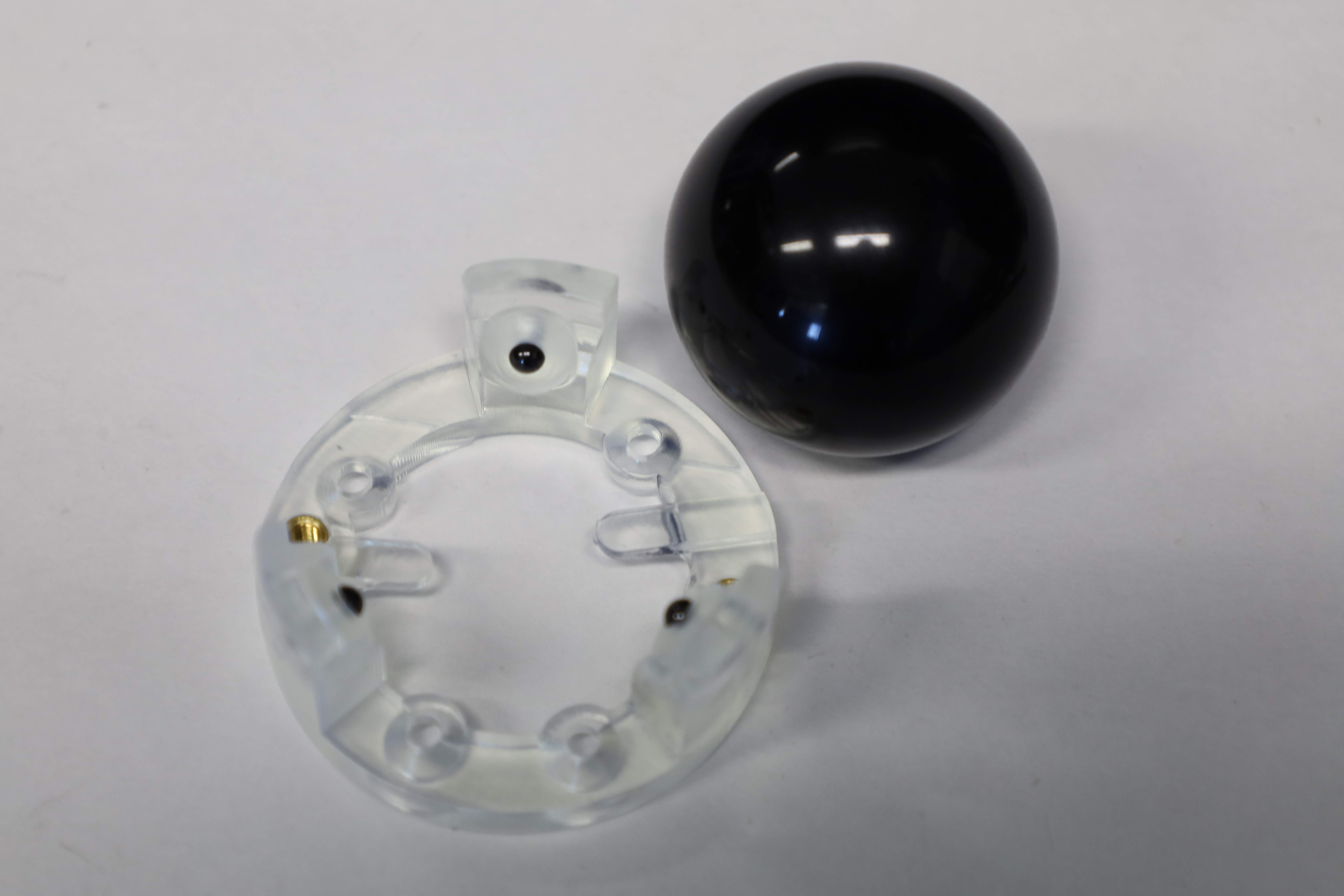
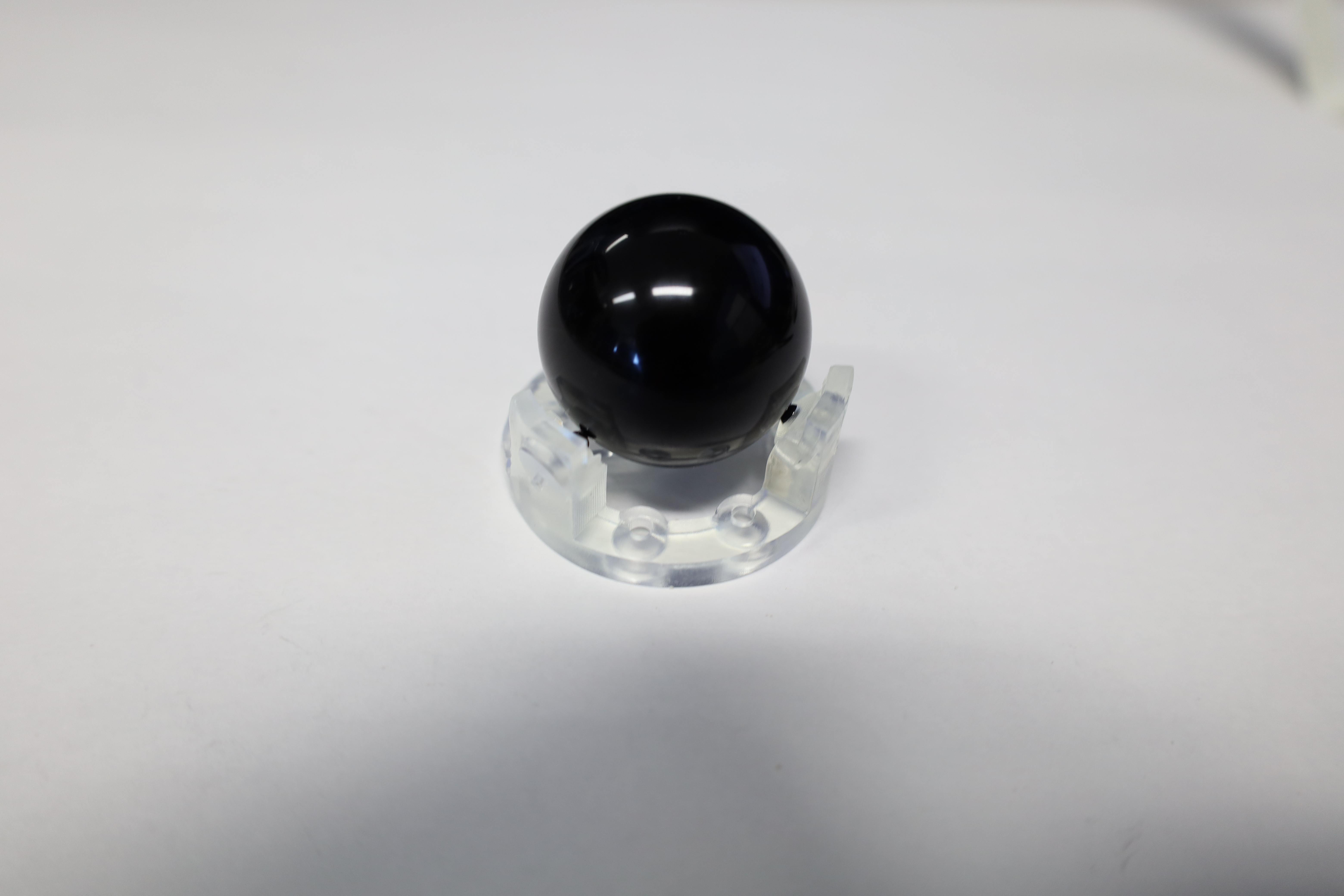
Next, the trackball sensor is sandwiched between the bottom adapter and the bottom sensor cover plate by screwing with the appropriate size screws. Those screws are smaller than the ones that hold the bottom plate to the case.
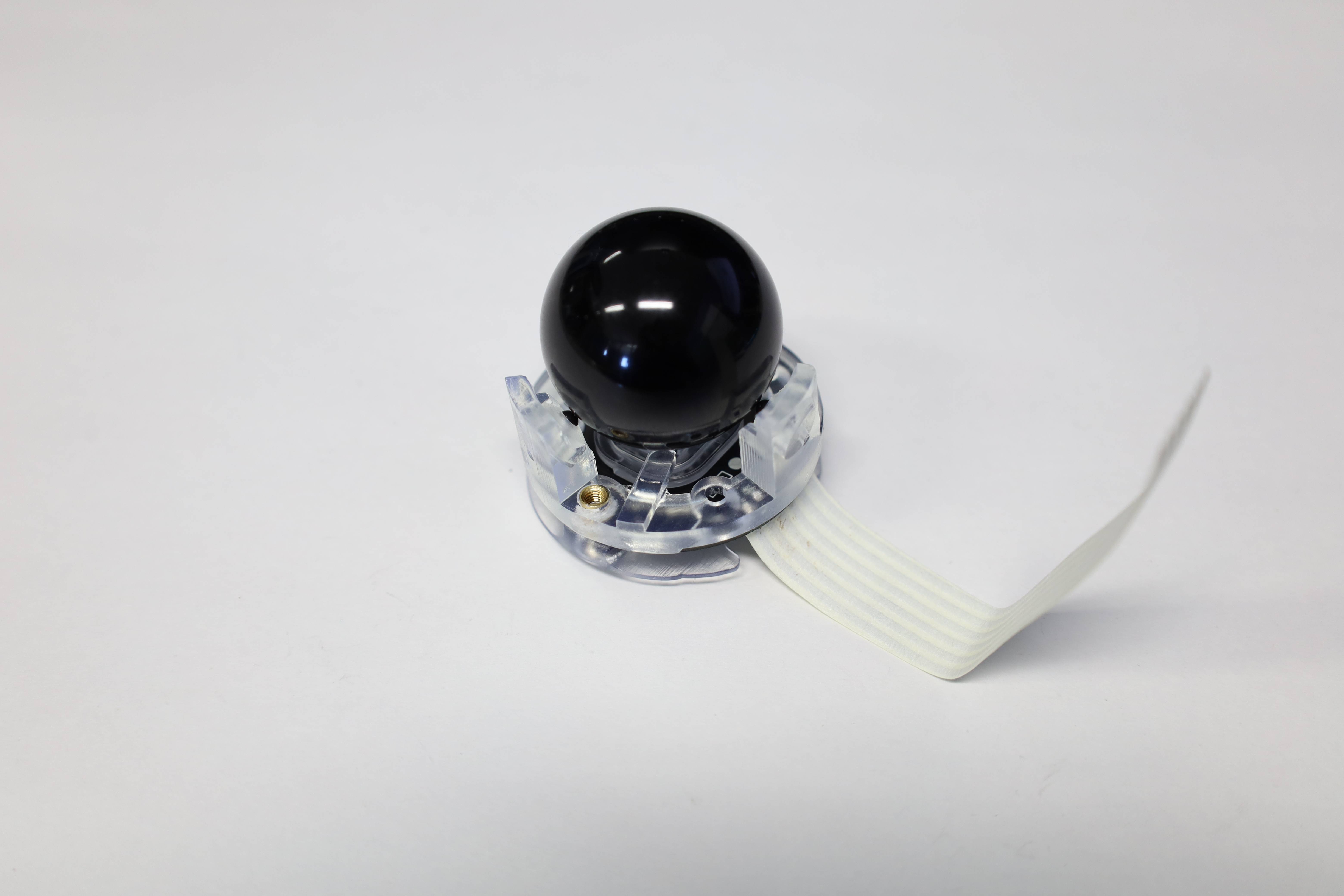
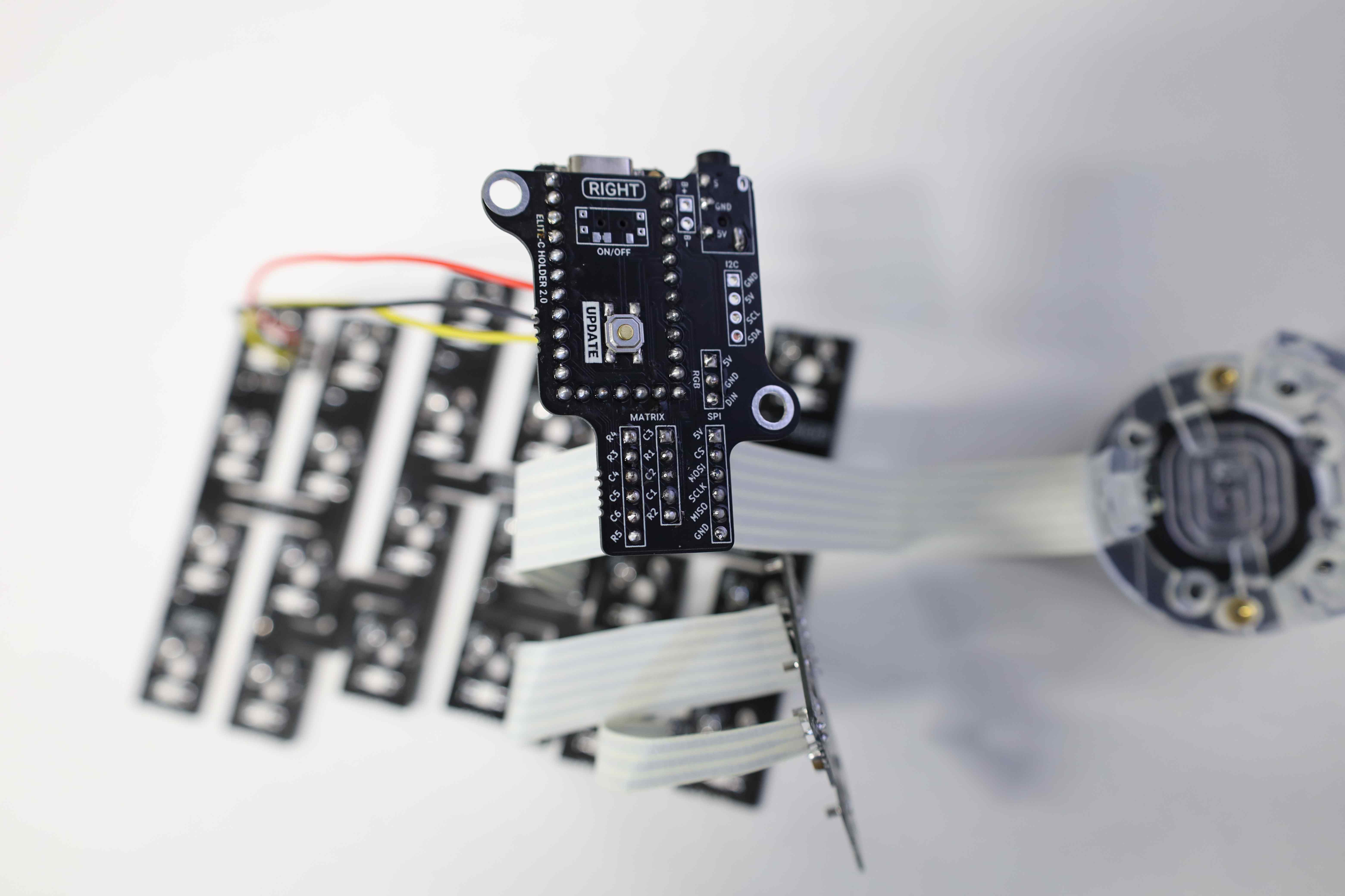
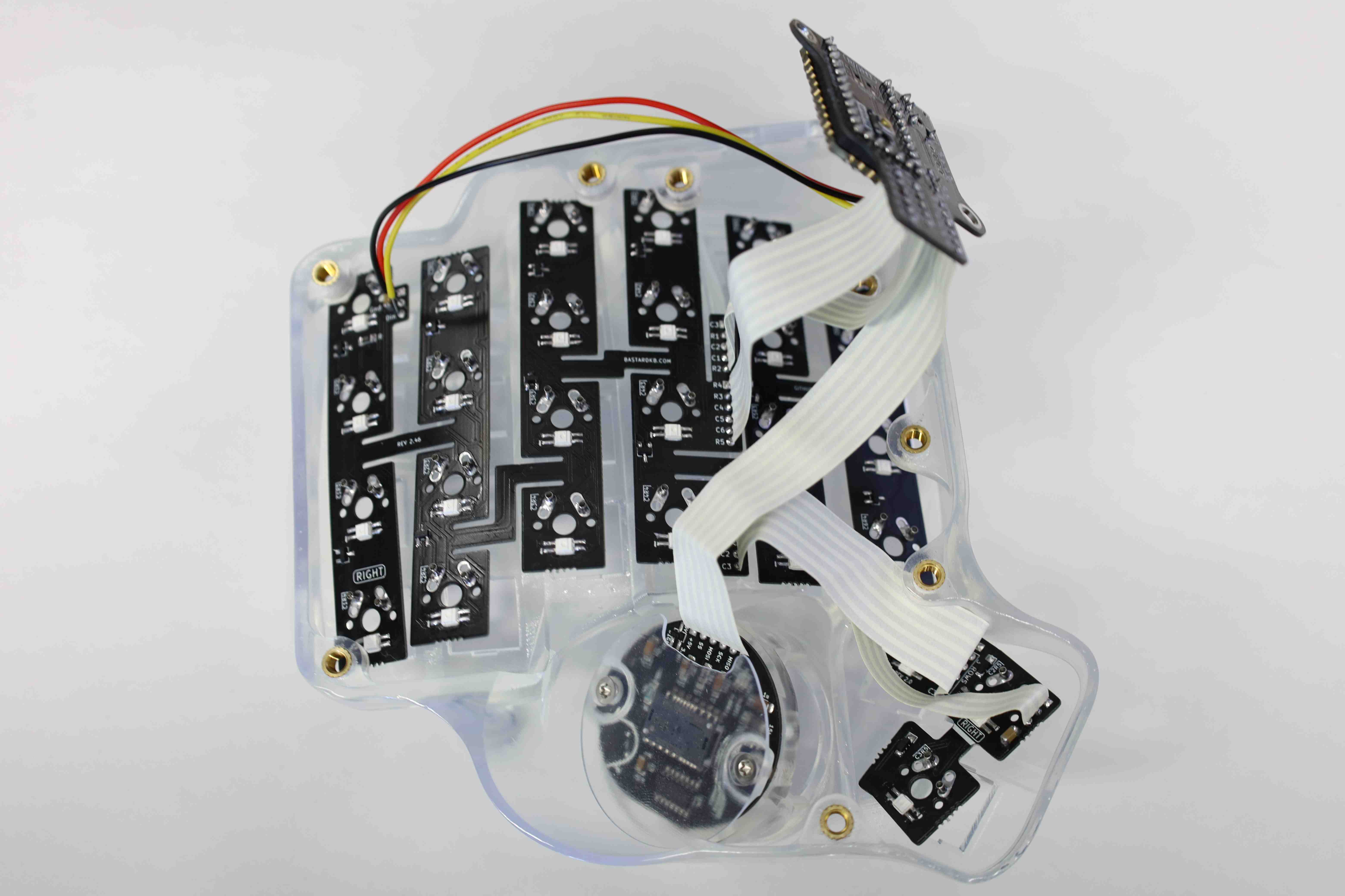
Next, the main PCB, MCU shield, and trackball sensor will be connected.
The details on how to connect the pins are again provided in the official build guide. Those details are dependent on which hardware version is used, so the following should only be taken as reference. This part especially highlights the main advantage of the v2 shield version over the v1. Namely, there is no more need to solder the ribbon cables directly onto the Elite C. Instead, they can be directly soldered to the extended v2 PCB. The legends on both sides help with aligning the pins of the ribbon cables adequately. Before soldering anything, one might also want to check the orientation and alignment of the board with the case. Make sure that the sensor will not face the bottom side of the case, among other things.
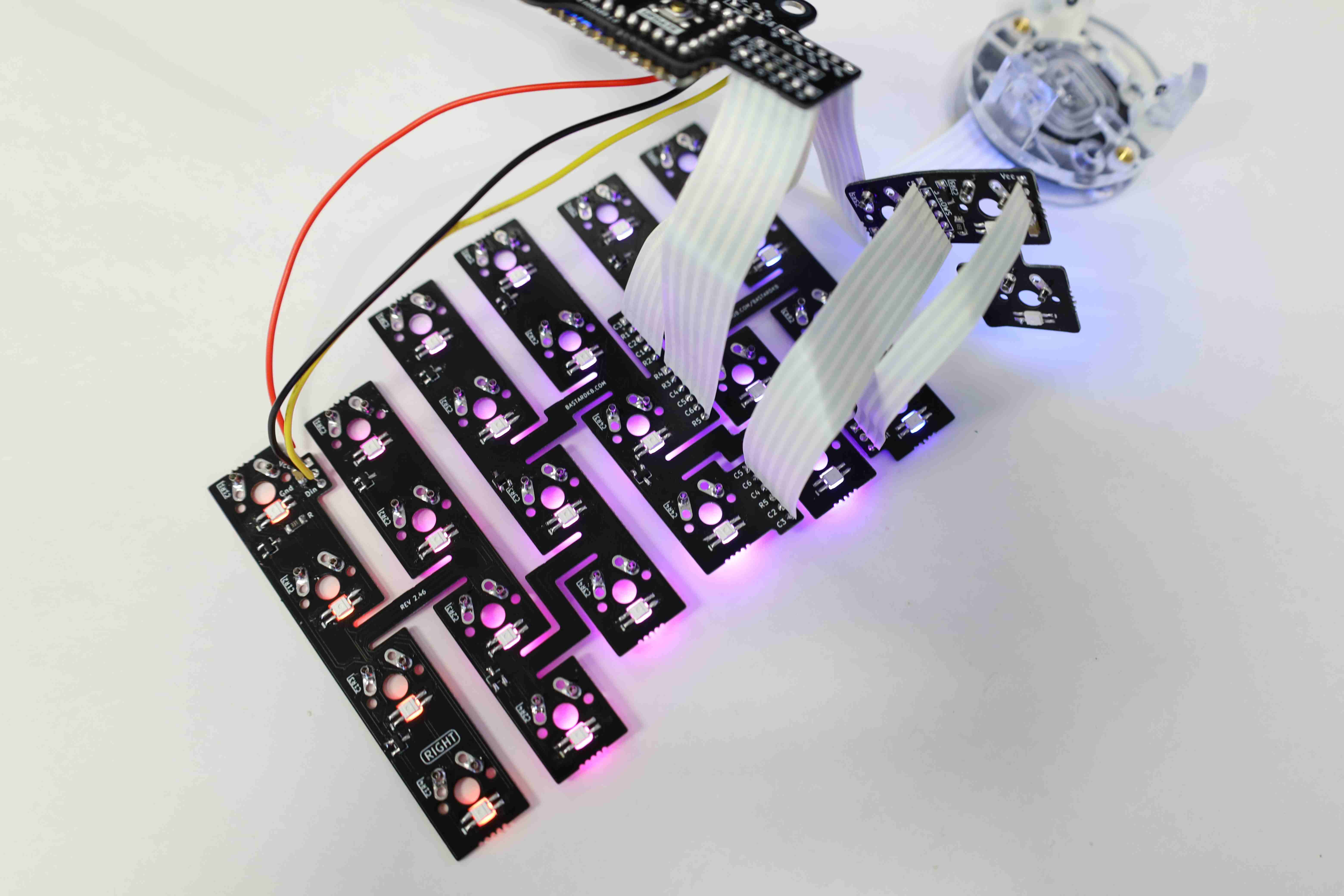
4.8 Preliminary testing
Before doing anything else, just as for the Left Scylla half board, the electronics are tested to make sure that the RGB LED all lights up, and that the key switches are also working. We can also take this opportunity to check that the trackball makes the cursor move on the screen.

4.9 Case assembly
The final step for this half of the keyboard, mounting everything into the case. First, the sensor top adapter has to be gently inserted into the hollow part of the case that will hold the trackball. That part is relatively fragile compared to the other regions of the case, hence some additional care and attention when working around is warranted.
Proceed to fit the PCB into the case, screw in the trackball, then progressively install the switches. Again, the details on how this is done are already documented in the corresponding section of the Left Scylla half board hence skipped in this section.
Special mention of the Gorilla taped for holding the PCB to the case because the key switches that fit into the Mill-Max sockets are not always strong enough to hold the flexible PCB to the case.

Closing the bottom, before also adding the 30 degrees tents.
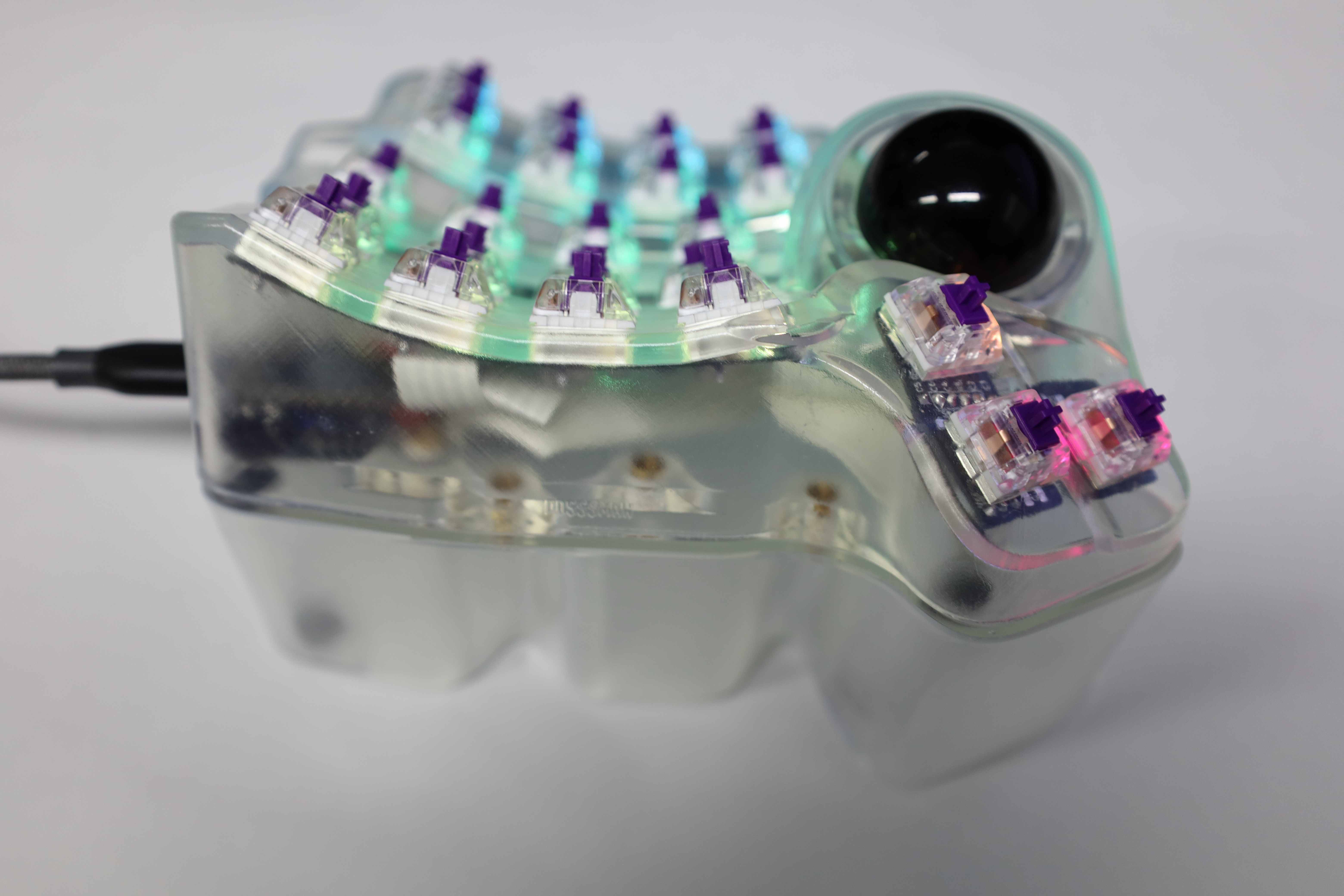
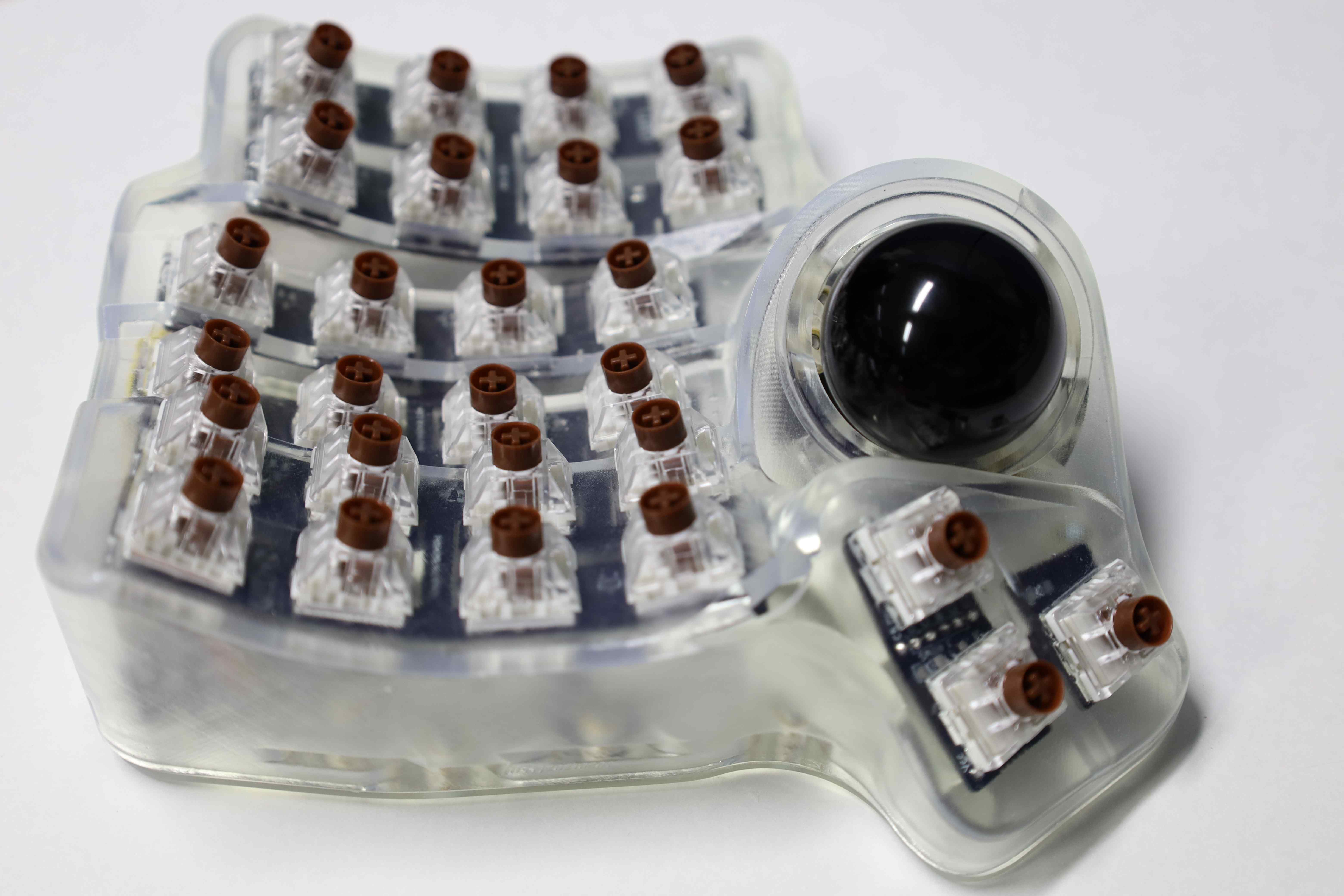
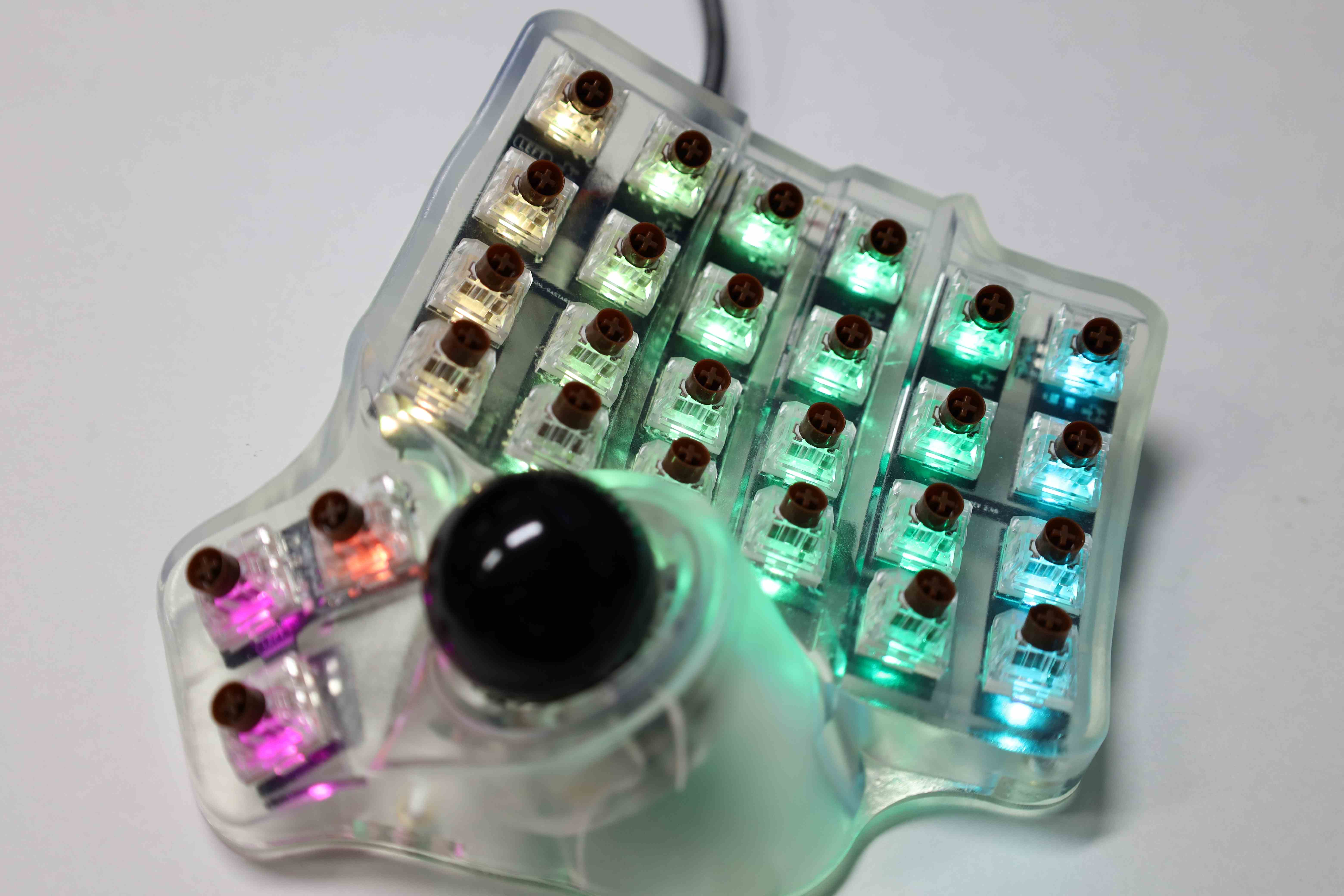
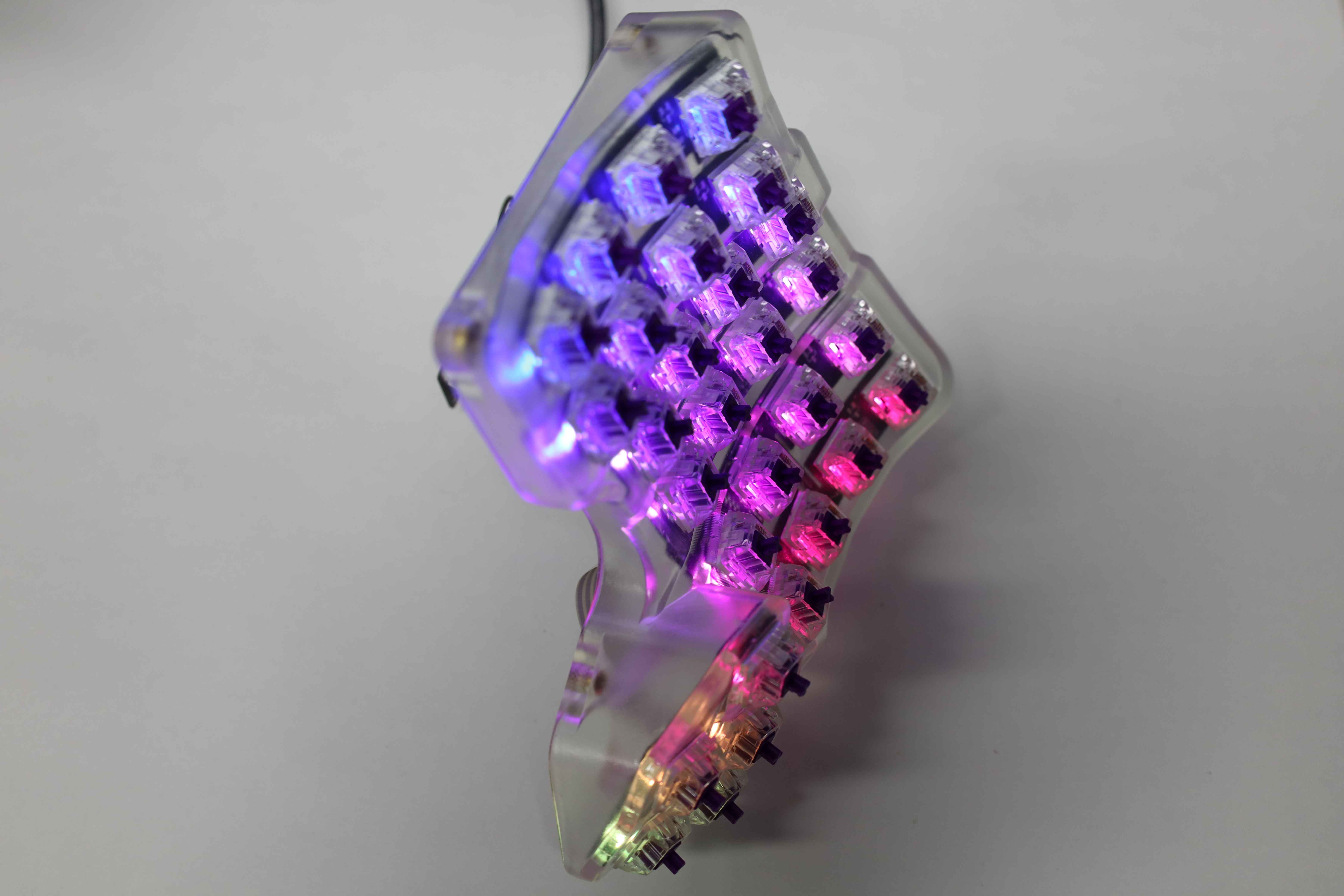
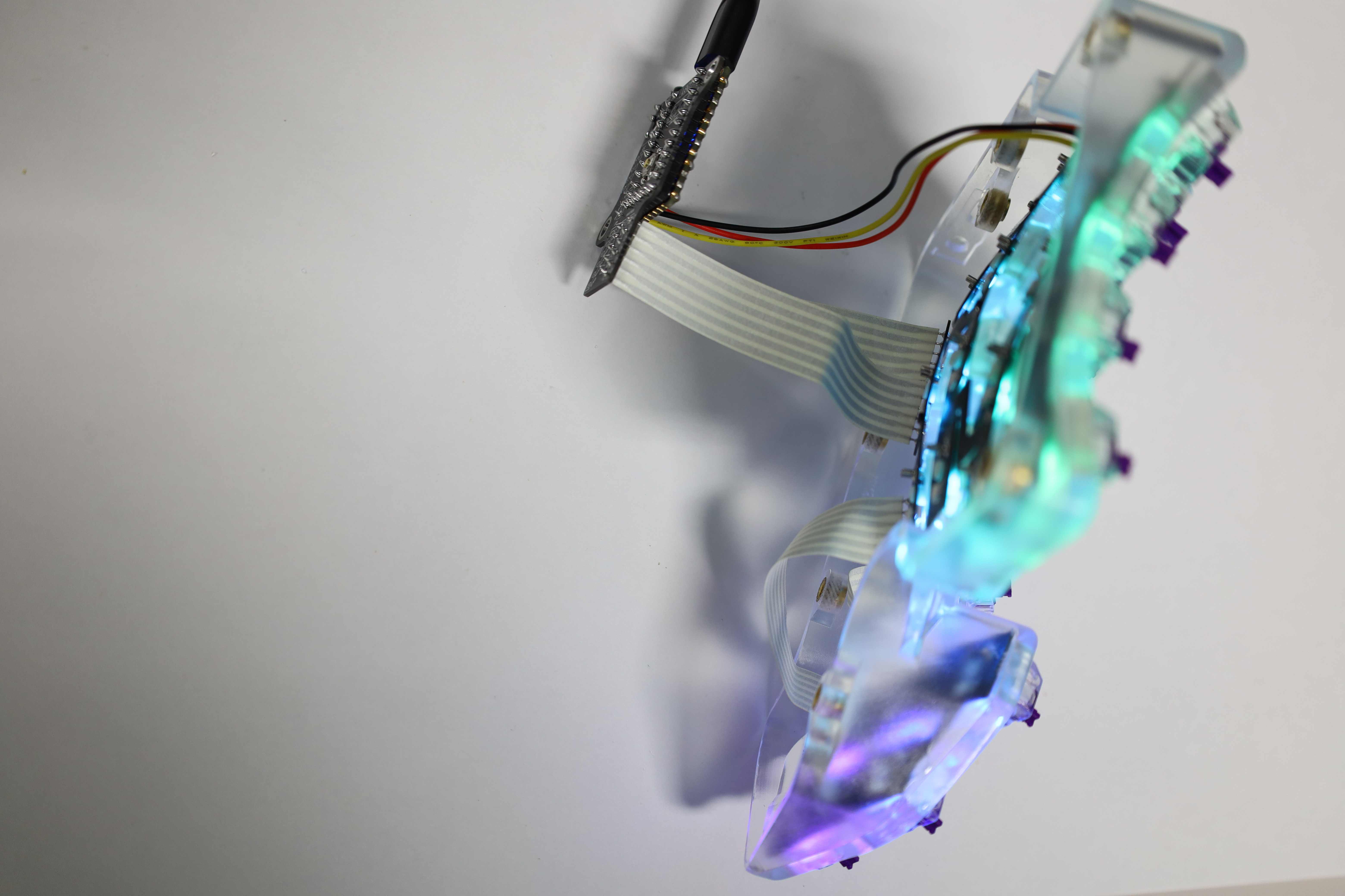
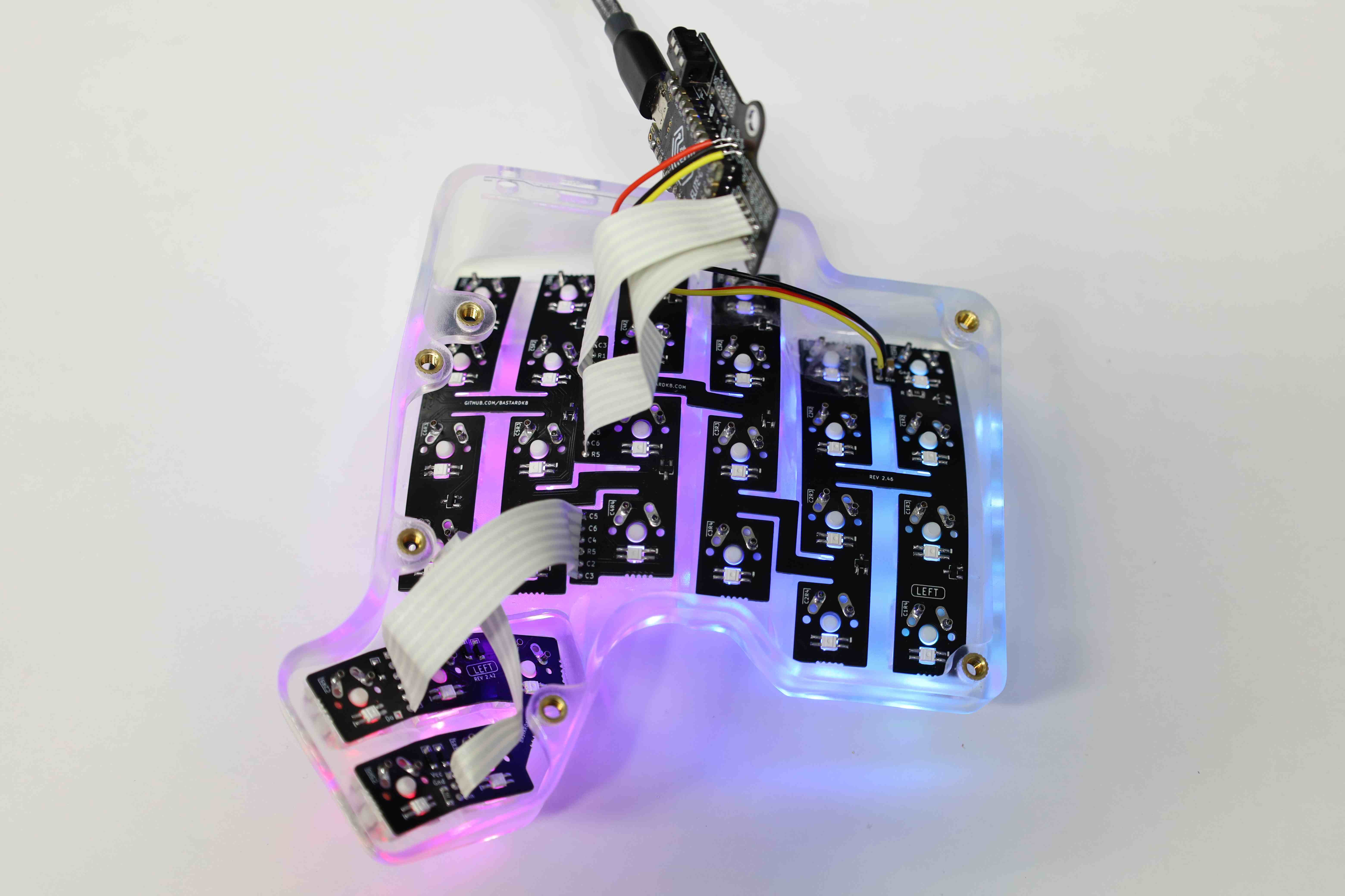
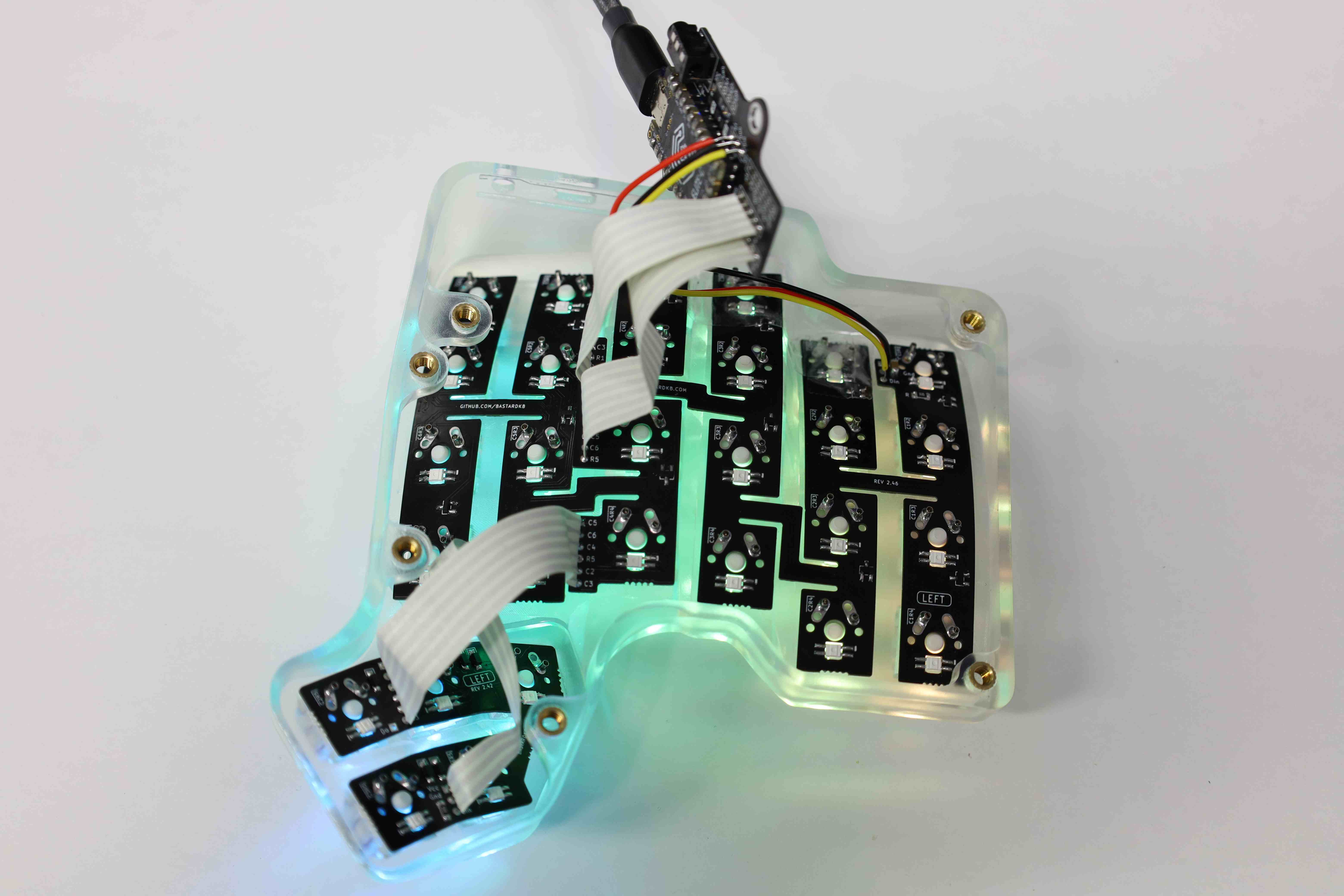
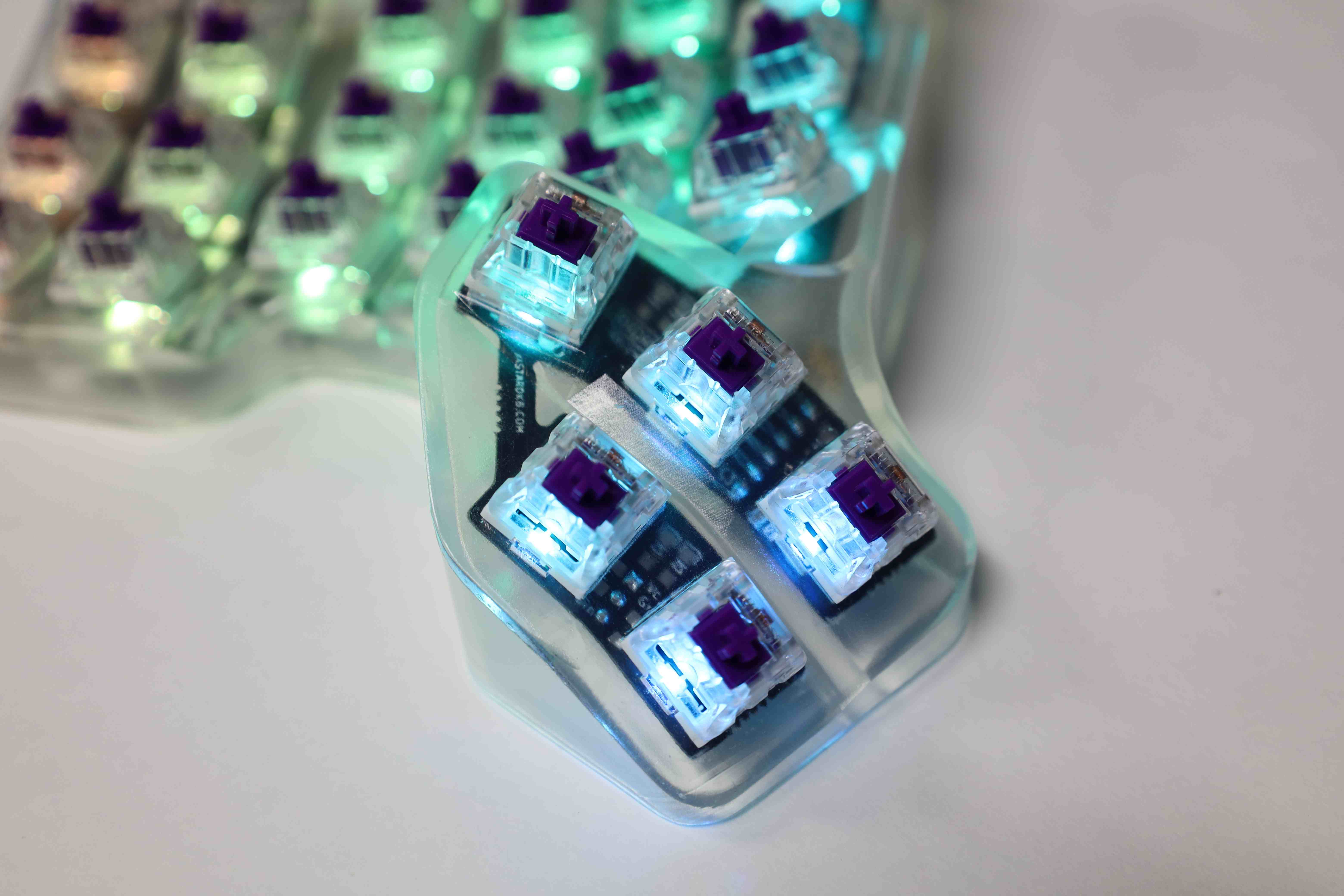
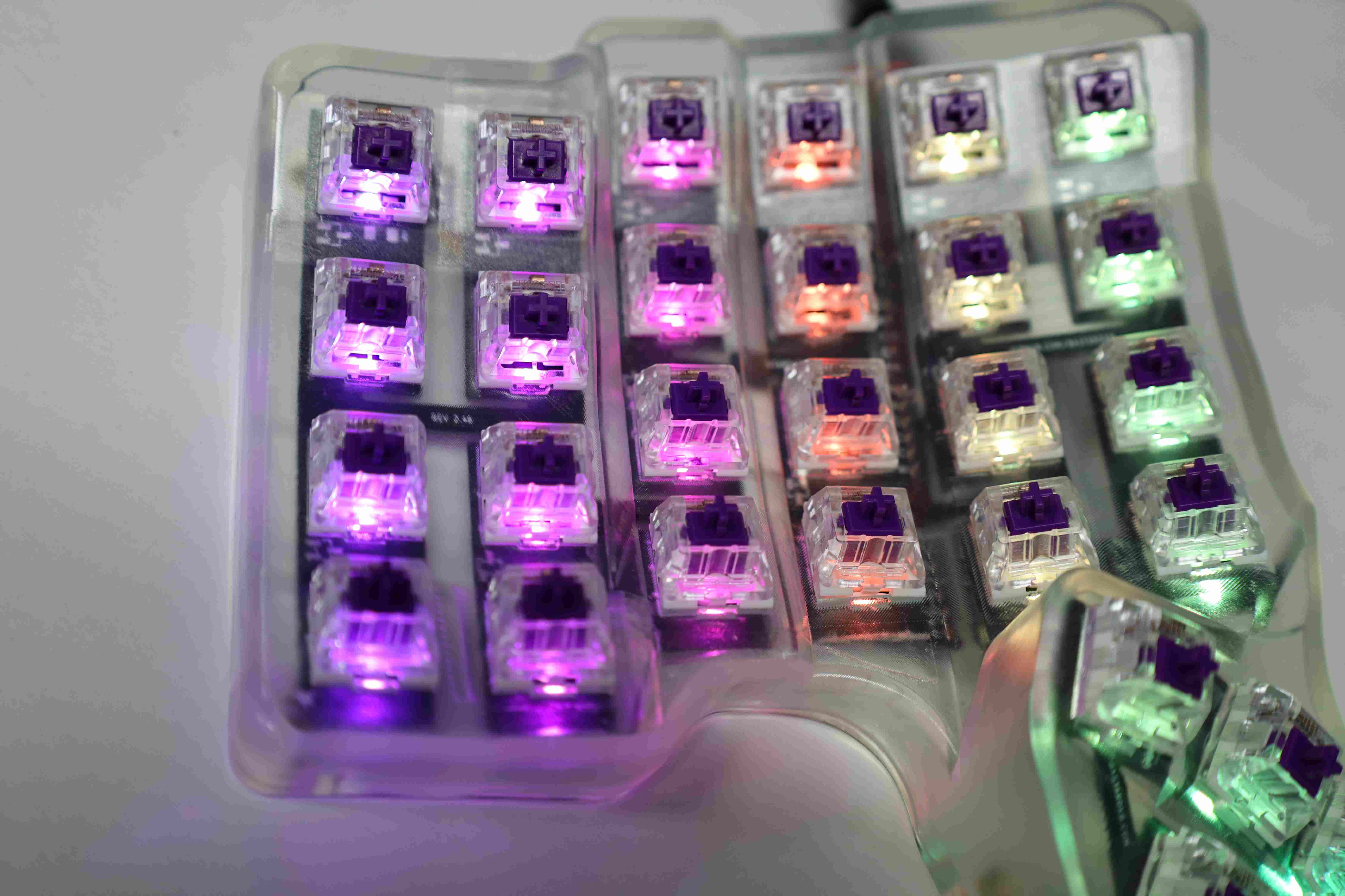
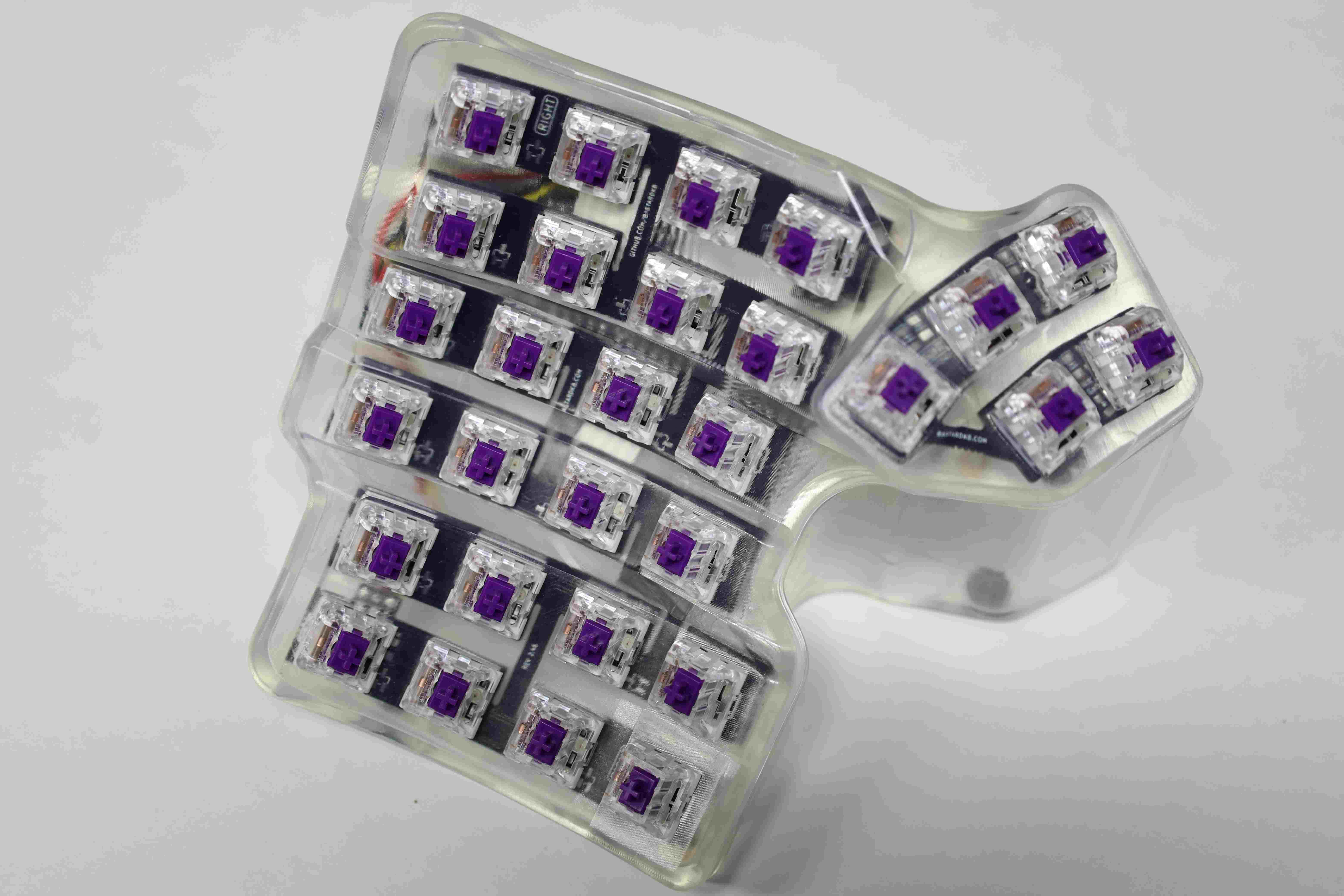
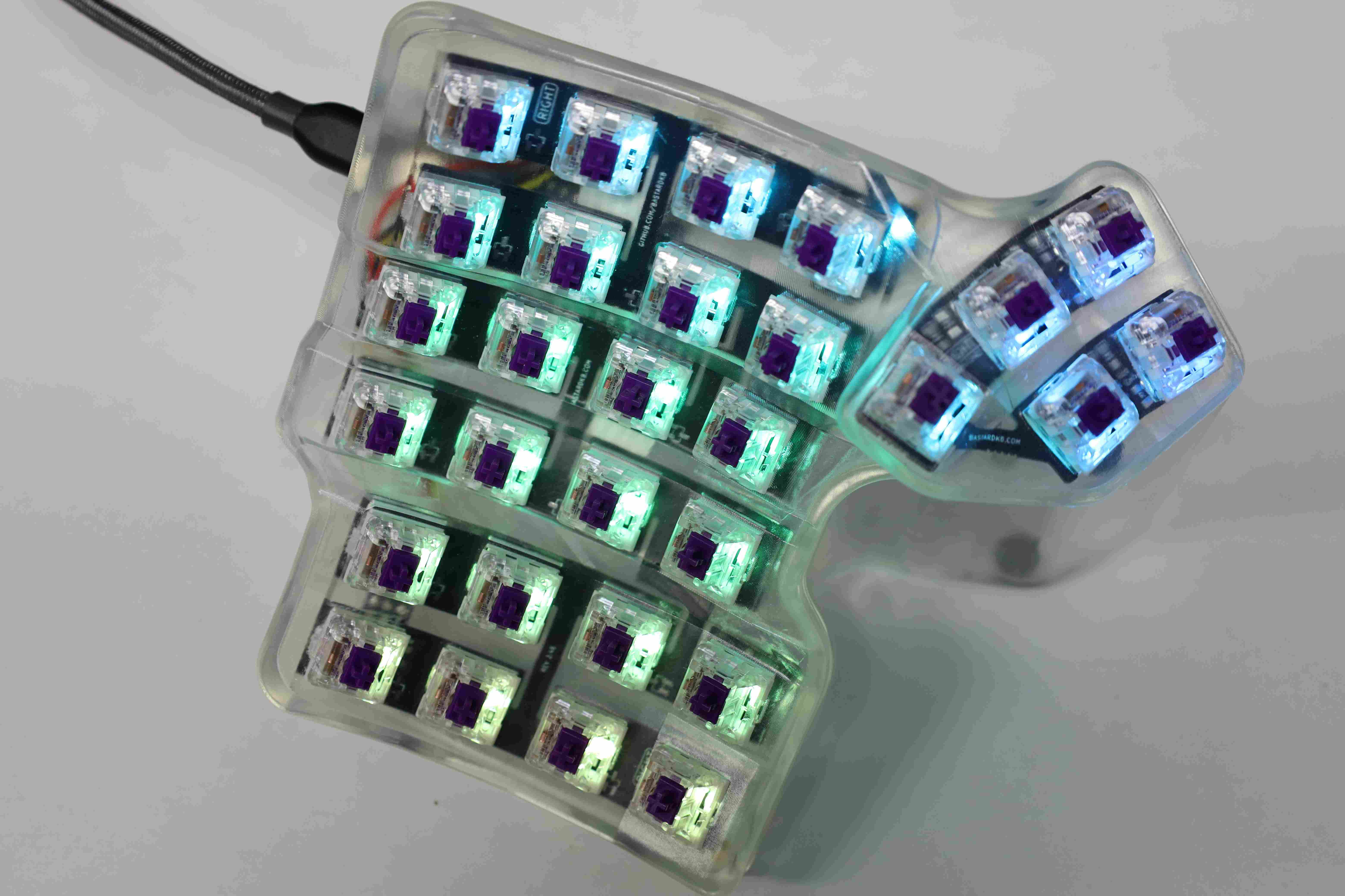
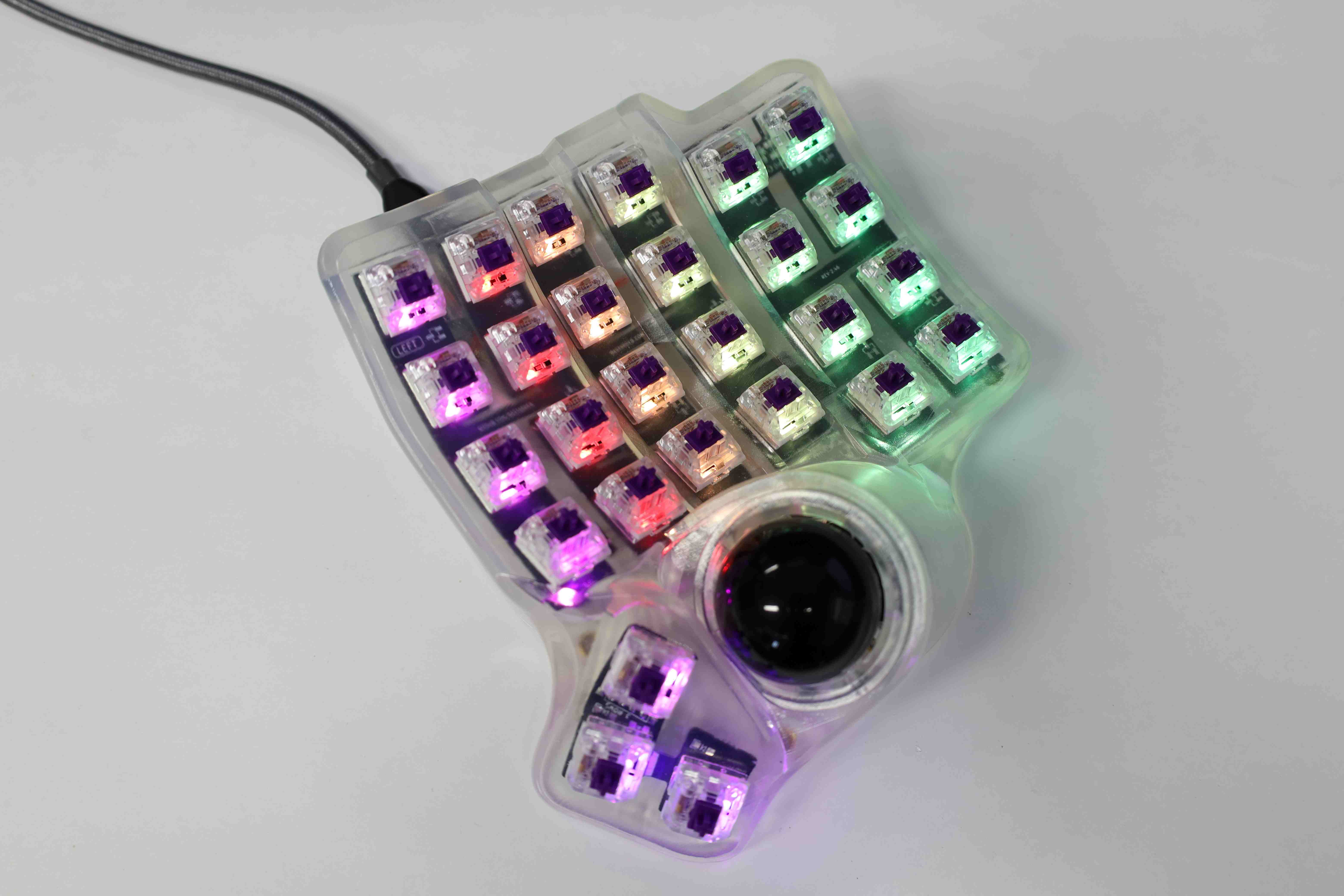
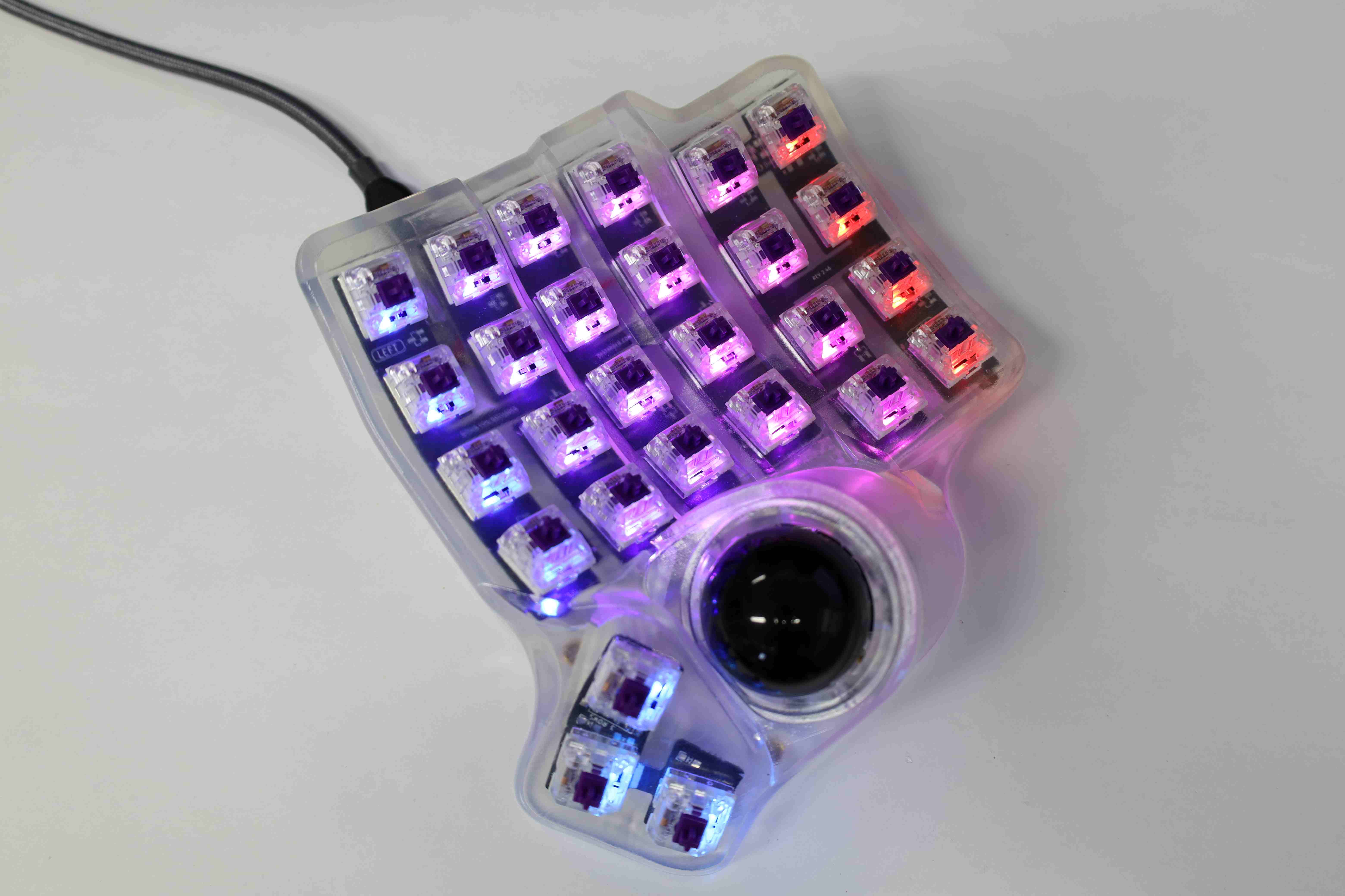
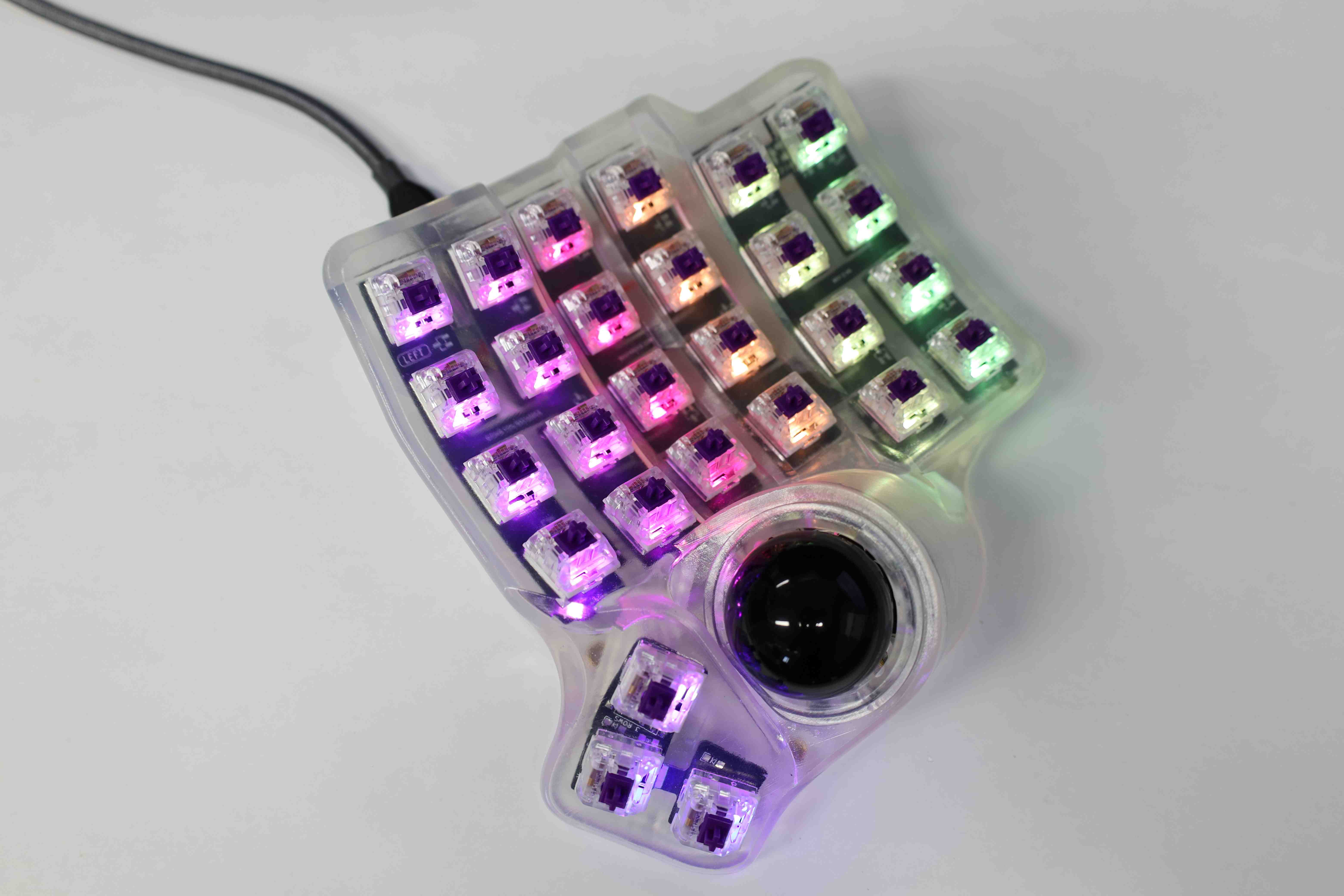
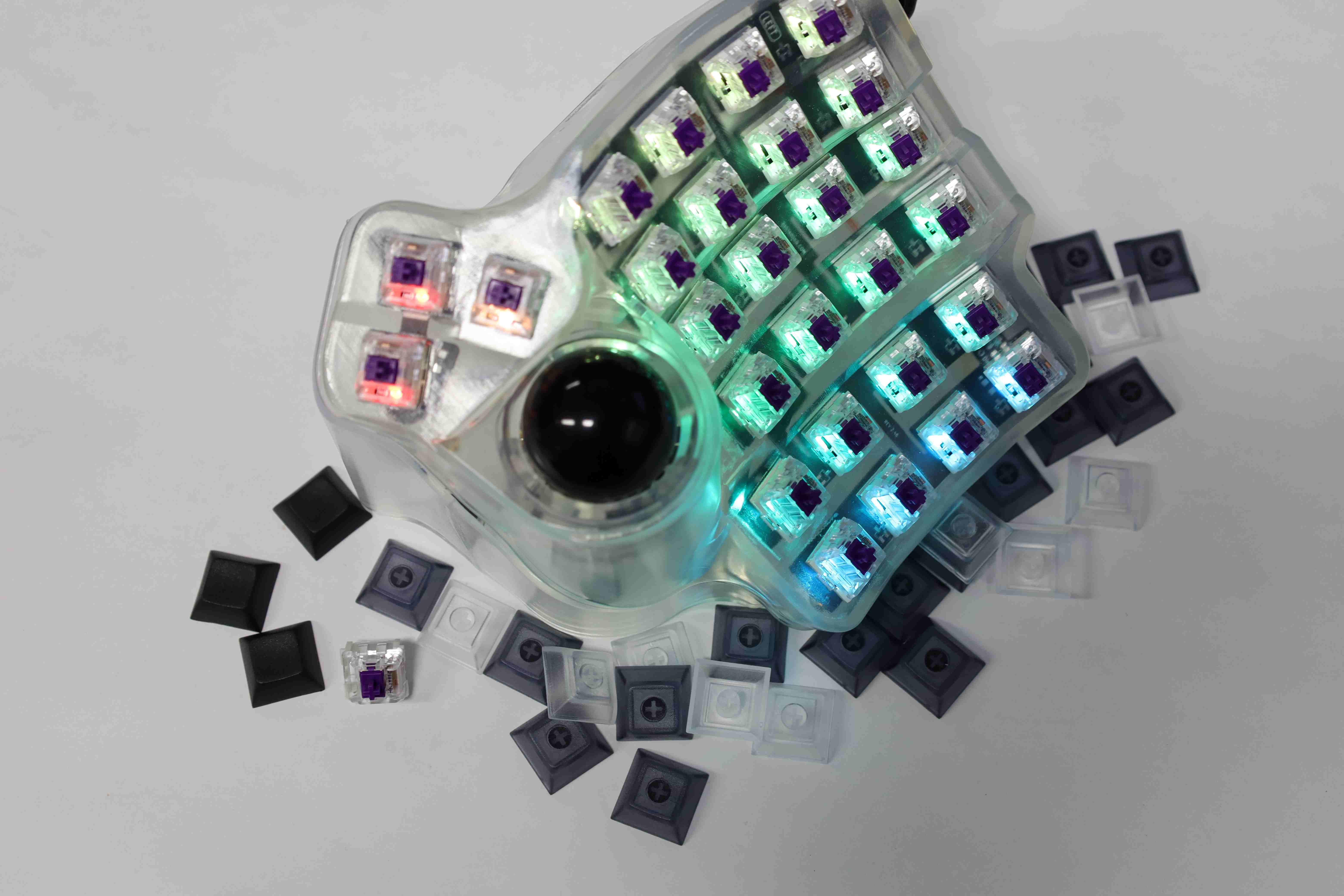
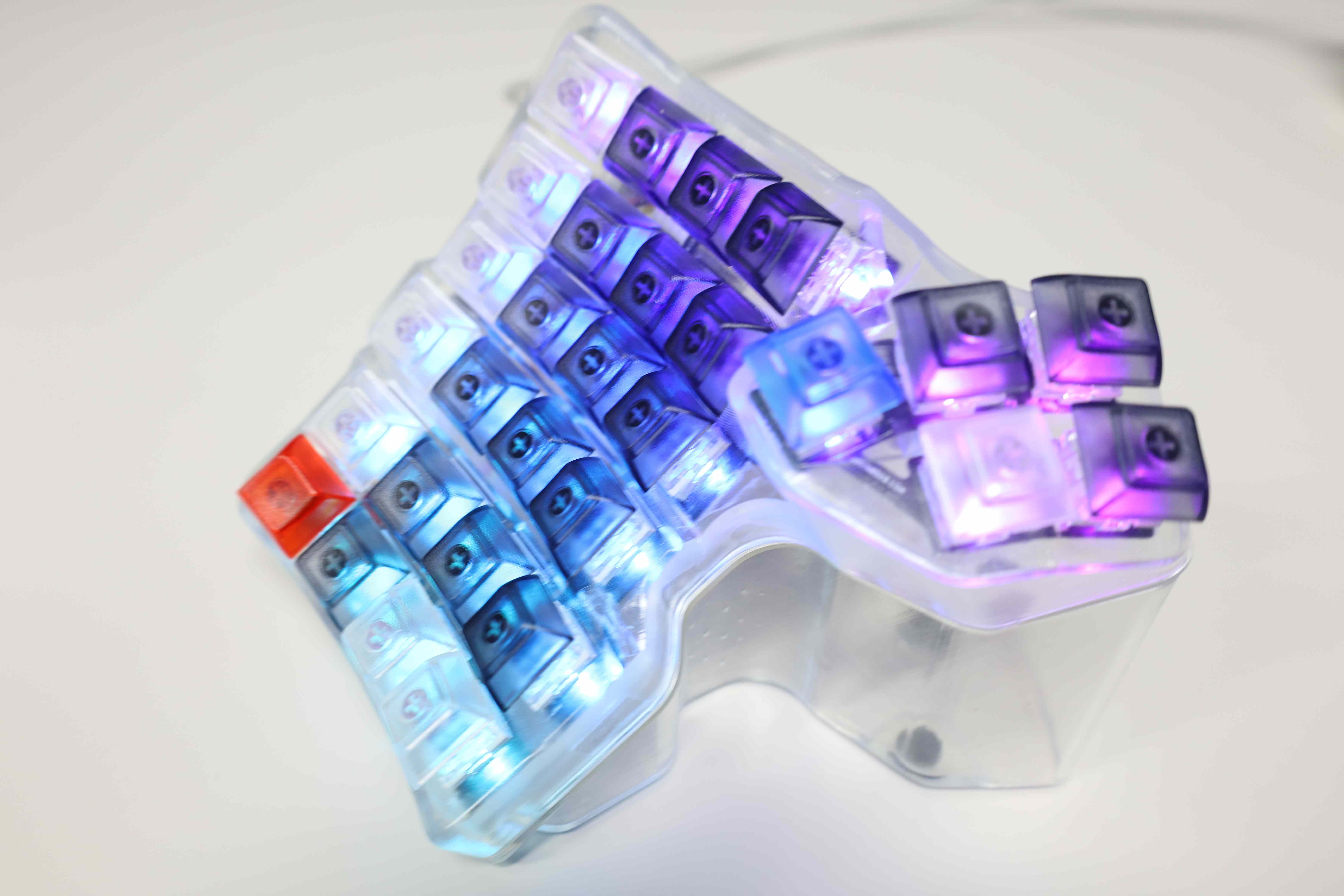
Showcasing the half board once the key switches and the 30 degrees tent are installed, with and without RGB effects:


The final step is the mounting of the keycaps.

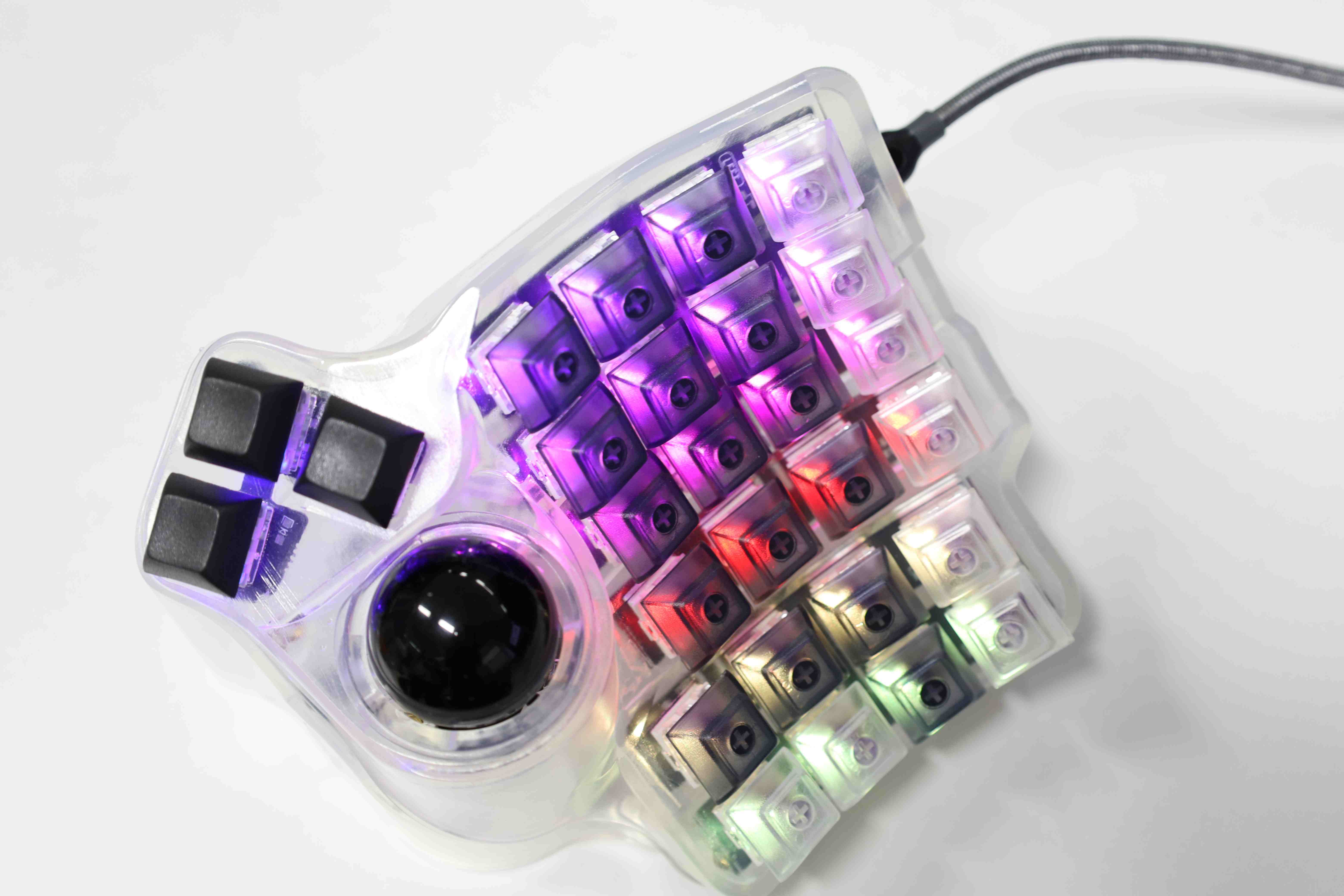
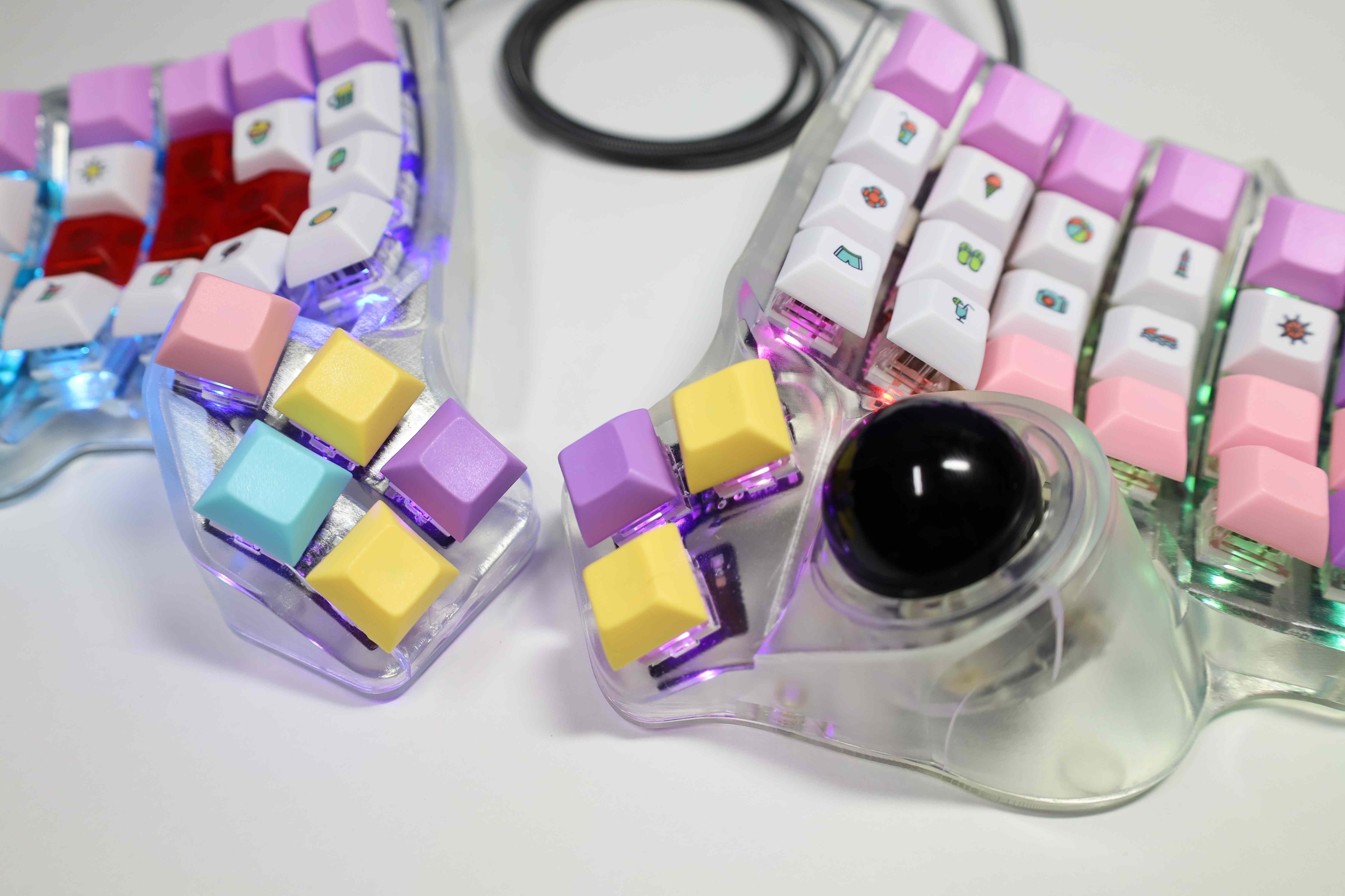
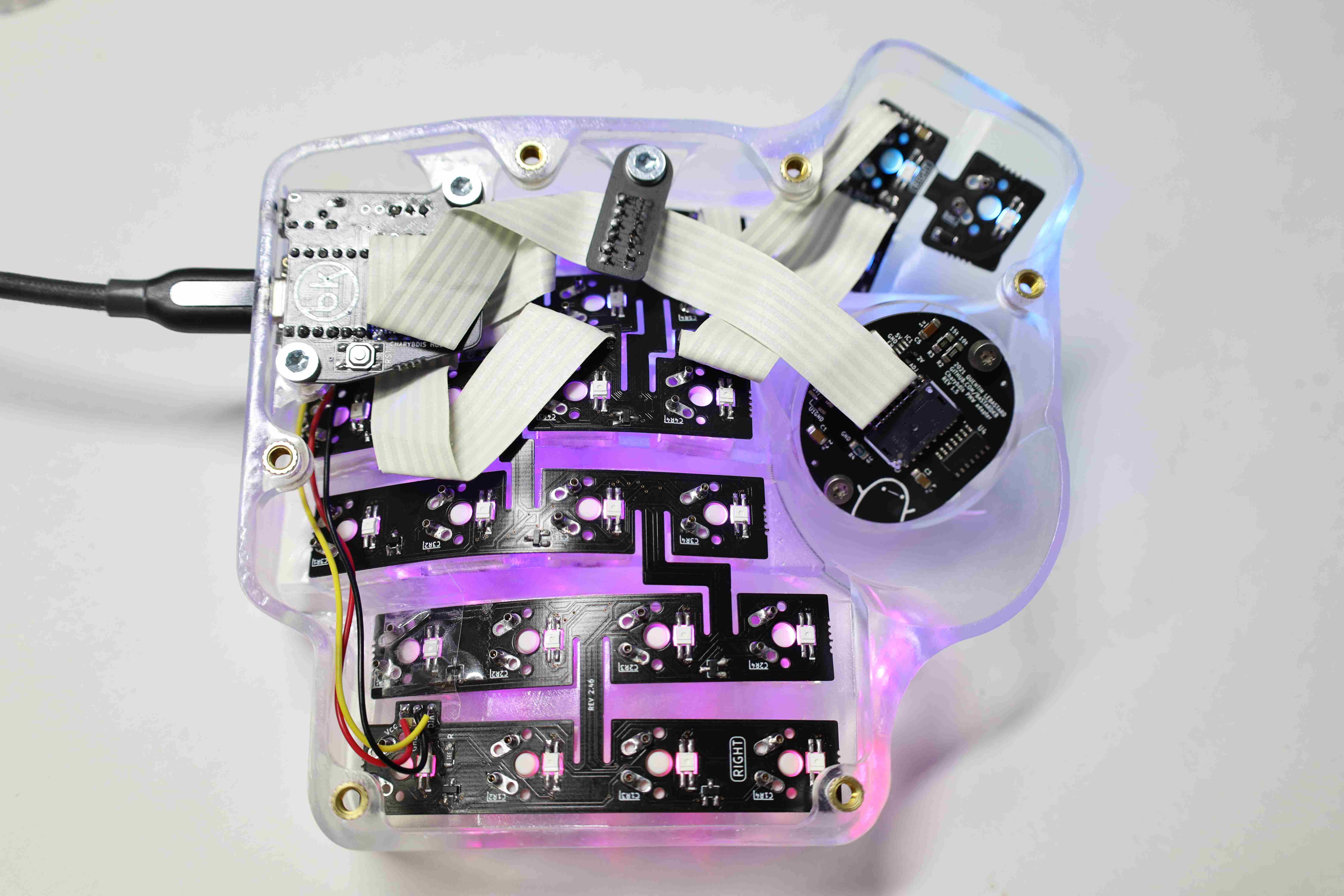
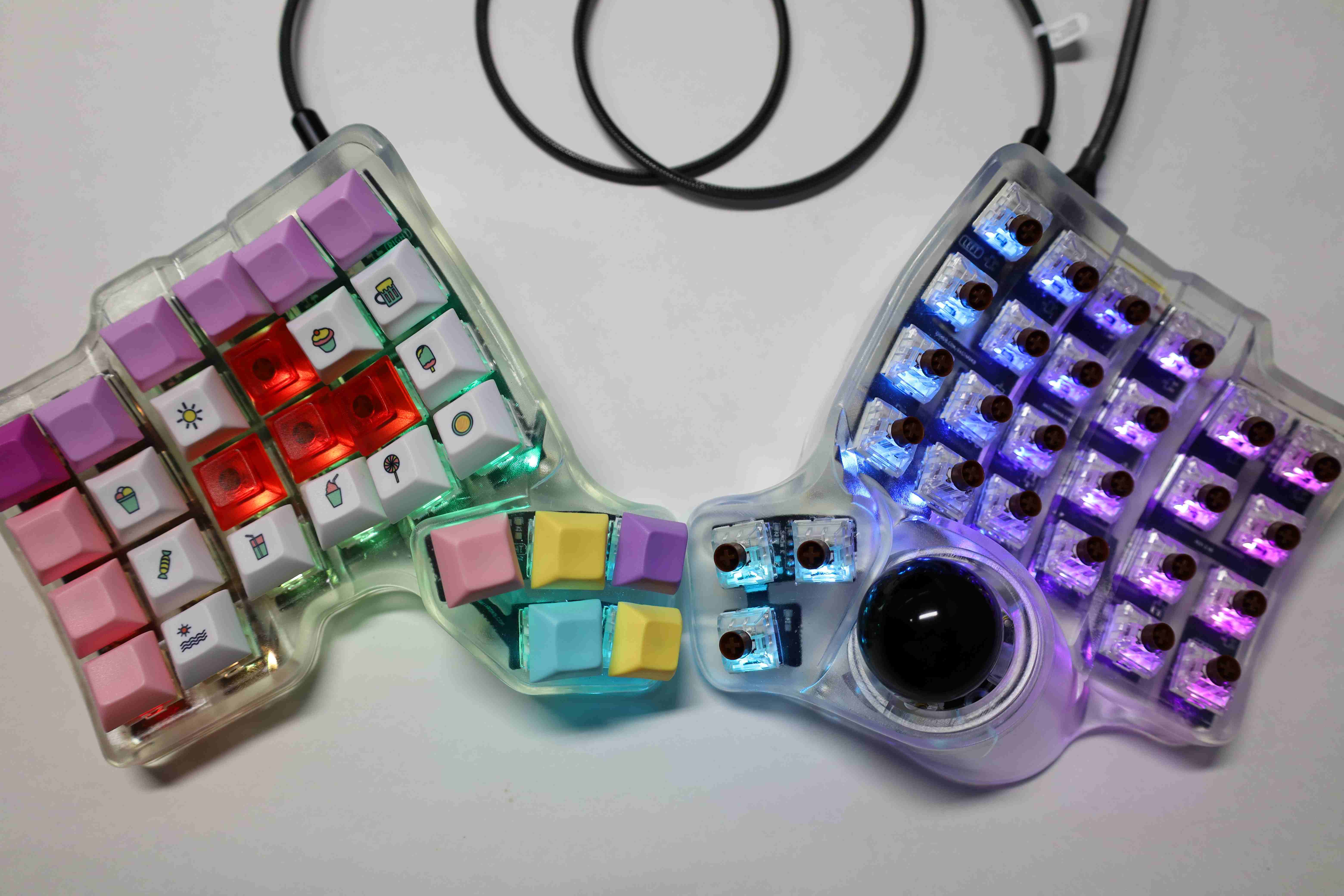
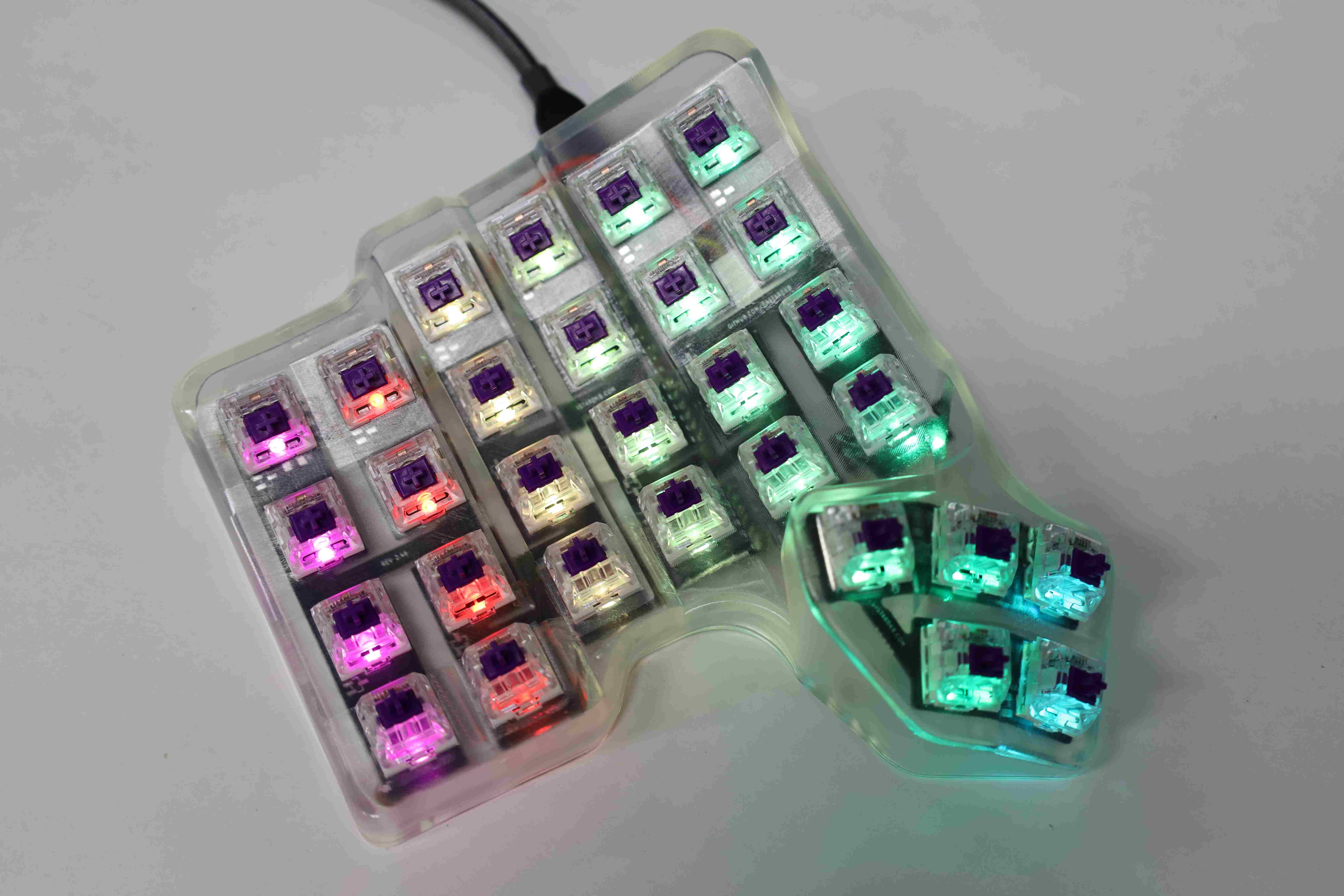
5. Final build showcase
That is it as far as the hardware is concerned. Both sides have been assembled, the electronics have been confirmed to work, then the cases were closed and cleaned up.
Once plugged, the default RGB animation is a multicolored wave moving from left to right:
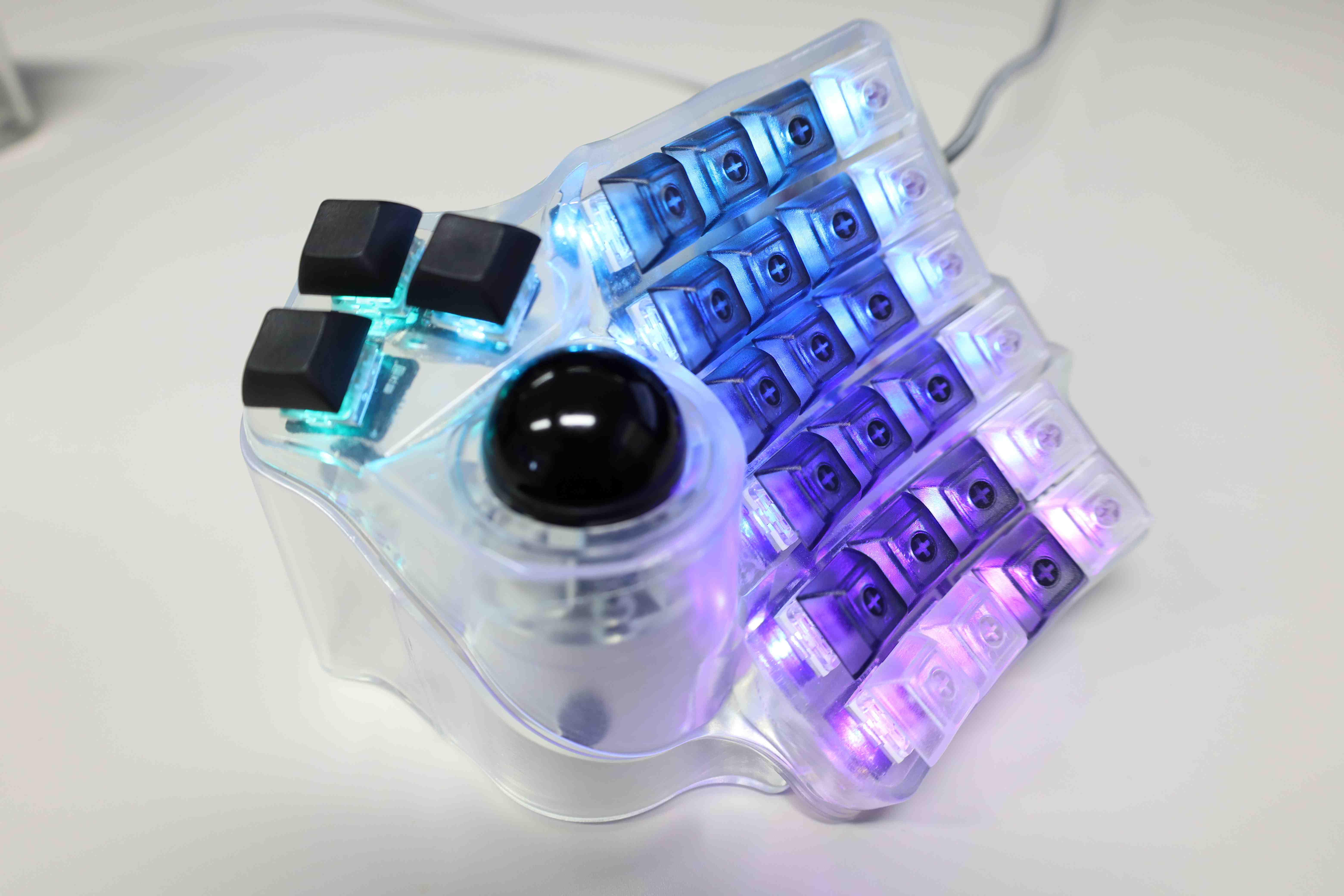

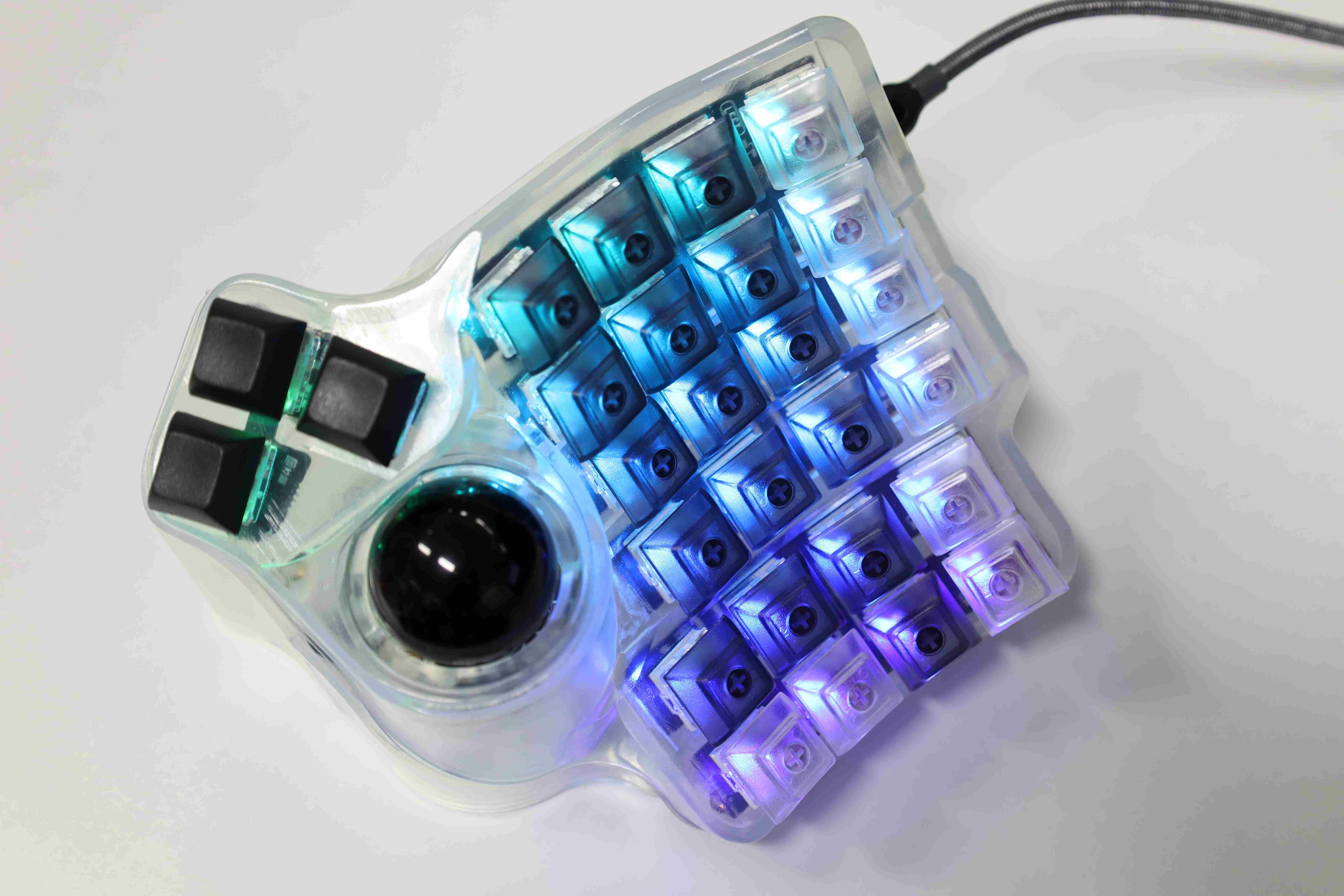
Ultimately, I have settled for a slowly breathing pattern with a uniform cyan-ish color.
Key layout and firmware
The firmware is based on the Bastardkb fork of the qmk_firmware.
Building on top of my previous experience with the ErgoDash keyboard, I have designed a transitionary layout that matches personal preference.
The layout setup was done using the QMK Configurator online tool.
The final layout is exported as JSON file, which will be used to generate a keymap.c object that is further compiled into the firmware to be flashed on each board.
The outline of the qmk firmware tool setup and flashing would be as follows.
1. Installing QMK and cloning the firmware repository
For the qmk tool itself, the official QMK documentation website has all the instructions to install it.
Using a Linux system, and once the qmk setup step is passed, the qmk command should be available through the terminal.
2. Cloning the firmware repository Next, I clone the firmware repository, in this case, my fork of qmk_firmware that also incorporates that of bastardkb. Since I am maintaining firmware for different keyboards, I have segregated the files for each keyboard’s firmware under a different branch. In this case, I use the dosssman/qmk_firmware’s charybdis_dosssman branch.
git clone https://github.com/dosssman/qmk_firmware --branch charybdis_dosssman
cd qmk_firmware
qmk setup -H .
make git-submodules
The second last line will indicate to the previously installed qmk tool to use the cloned repository as a base to build and flash the firmware.
The last lines install dependencies if needs be, in case it is suggested in the output of the previous line.
The charybdis_dosssman branch incorporates a few additional changes that make the flashing easier for me.
The first is that instead of setting the master board as the right side by default, I enable EE_HANDS which allows me to specify which side of the board is being used just before flashing.
This is done by changing the keyboards/bastarkd/charybdis/4x6/config.h from having:
#define MASTER_RIGHT
to
#define EE_HANDS
I also enable mouse keys by setting MOUSEKEY_ENABLE = yes in the keyboards/charybdis/rules.mk. Note that this will consume around 3% of available byte space on the MCU.
3. Creating a custom layout profile
Assuming the bastardkb-qmk repository was freshly cloned, first I copied the default directory keyboards/firmware/bastardkb/charybdis/4x6/keympas/ into a new directory: keyboards/firmware/bastardkb/charybdis/4x6/keympas/.
This directory will hold the files related to the custom keymap.
Next, using the QMK Configurator Online Tool, the following layout is generated.
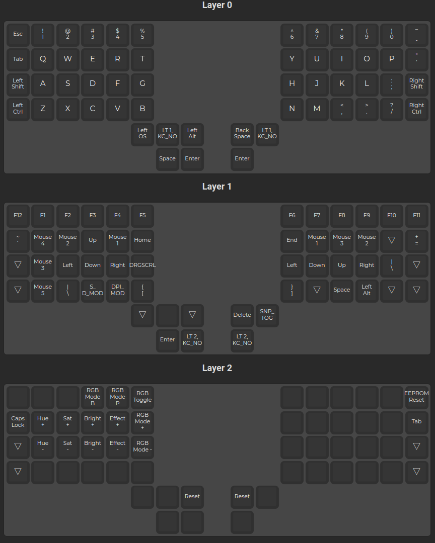
Using the export tool of QMK Configurator, it is saved as dosssman.json under the keyboards/firmware/bastardkb/charybdis/4x6/keympas/ directory.
Next, navigate to this directory, and generate the keymap.c file based on dosssman.json:
cd /path/to/keyboards/firmware/bastardkb/charybdis/4x6/keympas/dossssman
qmk json2c dosssman.json > keymap.json
cd /path/to/qmk_firmware # Come back to the root folder of the cloned qmk repository
4. Flashing both halves of the keyboard
Then, from the root of the qmk firmware repository, I run the following two commands which will compile the keymap.c and other core firmware code source into the .hex file that will be written onto the MCU.
Each command has to be executed with the corresponding half of the keyboard plugged, and the reset button pressed when prompted by the qmk tool.
# For the left half of the keyboard
make bastardkb/charybdis/4x6/v2/elitec:dosssman:dfu-split-left
# For the right half of the keyboard
make bastardkb/charybdis/4x6/v2/elitec:dosssman:dfu-split-right
With this, the keyboard is ready to go.
Some additional notes:
- Depending on which MCU shield version is used, the flashing command
make bastardkb/charybdis/4x6/v2/elitec:dosssman:dfu-split-lefthas to be adapted to use eitherv1orv2, at the time of this writing (2022-08). - QMK Configurator supports custom keycodes, namely the ones that enable drag scroll, mouse sniping, and DPI on the fly configuration. This can be done by dragging the “Any” key onto the keyboard layout, then typing in the custom key code.
- As of 2022-04, the trackball’s advanced features such as mouse drag scroll and snipping do not work if the master board (connect to USB C) is Scylla one.
- Additional RGB profiles can be added to the firmware based on the QMK firmware’s official documentation.
As a reference, here were the steps used to add a unicolor breathing mode: in the
keyboards/firmware/bastardkb/charybdis/4x6/keympas/dosssmanfolder, editedconfig.has follows:// Rainbow swirl as startup mode. # define ENABLE_RGB_MATRIX_CYCLE_LEFT_RIGHT # define ENABLE_RGB_MATRIX_BREATHING // new addition # define RGB_MATRIX_STARTUP_MODE RGB_MATRIX_CYCLE_LEFT_RIGHTThe supported RGB profiles were taken from QMK Docs.
Acknowledgment
- Quentin Lebastard for his thoughfull desing of the Charybdis and Scylla.
- The BKB community on Reddit and Discord, and more generally, the open source community. Special thanks to Charly on Discord for hinting the need to use the proper firmware version for the V2 MCU shield.
- My university professor for enabling us to use the 3D printer.
- My labmate which now uses the build in Showcase 2 for the discussion and help.
Leave a comment